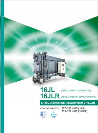
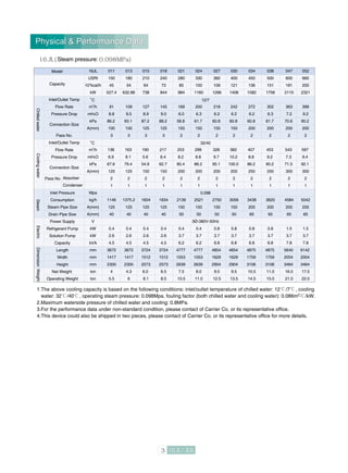
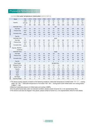
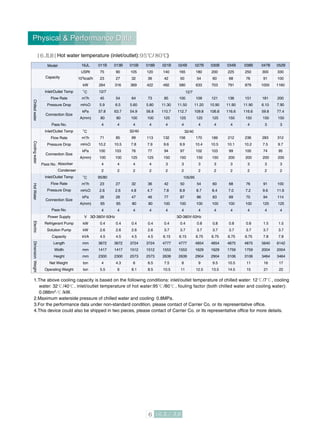
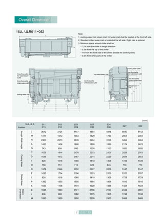
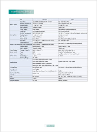
CARRIER ASIA CO., LTD.
(SINGLE EFFECT HOT WATER TYPE)
(SINGLE EFFECT STEAM TYPE)
LITHIUM BROMIDE ABSORPTION CHILLER
COOLING CAPACITY 527~2321 KW (16JL)
239~2321 KW (16JLR)
Standard: 125 /105
: 105 / 95
: 95 / 80
Product specification
Single effect hot water absorption chiller
Absorption product code
Carrier makes the world a better place to live
by creating a comfortable, productive and
healthy environment regardless of climate.
It is our mission is to be customer’s first choice
for air conditioning, heating and refrigeration
solutions everywhere around the world.
Features/Benefits
Single Effect Cooling Cycle
Heat Source and Usage
Physical & Performance Data
Overall Dimension
Foundation Dimension
Thermal Insulation
Hoisting
Specification Scope
Wiring Diagram
Standard Tubing Flow
Water Quality Control
Great Hall of the People,
Beijing, China
Kremlin, Moscow, Russia
White House, Washington, USA
Imperial Palace, Tokyo, Japan
Product specification
Single effect steam absorption chiller
Absorption product code
Inlet/outlet temperature of
operating hot water
1
2
2
3
7
8
9
10
11
12
14
16
Features / BenefitsFeatures / Benefits
Environmentally Friendly Chiller
Using water and lithium bromide which are natural as refrigerant medium, no CFCs;
Few moving parts enable quiet and vibration-free operation.
Cost-effective cooling alternative-energy chiller
The 16JL/JLR offers an alternative to avoid the high operating costs associated with electric-driven chillers.
Fired by low pressure steam or hot water or waste heat, the 16JL/JLR not only reduces or eliminates elect-
ric demand and/or reduce charges, but also allows the owner to take advantage of rebates and incentive
programs offered by many utility companies.
Superior part load, low cooling water temperature (15°C) operation
The standard concentration control system allows stable, part load operation at cooling water temperatures
as low as 15°C without a cooling tower bypass with Carrier unique refrigerant management system (US
patent: US6,260,364-B1), it has a continuous operating range from 100% to10% of machine capacity.
Automatic motorless purge system extends machine life, ensures optimum efficiency and performance
The Carrier motorless purge system protects against the potential hazards caused by non-condensable gas
produced continuously during machine operation, ensures long machine life and efficient operation.
Anti-crystallization controls maintain proper solution concentration
The 16JL/JLR automatically limits solution concentration in several ways to avoid both crystallization and
over-dilution to provide dependable, trouble-free operation.
Leak-proof hermetic pumps cut maintenance costs
Carrier’s proven solution and refrigerant pumps are leak-proof, completely self-contained, and hermetically
sealed. The hermetic design eliminates the need for a separate, complicated, and possibly leak-prone seal
water system, while providing leak tightness and longer machine life.
Superior corrosion protection
The 16JL/JLR incorporates a highly effective corrosion inhibitor to provide an extra margin of protection
against internal corrosion.
Rugged machine construction
Non-clogging, corrosion-proof spray nozzles ensure against both corrosion and possible blockage for
continuous, reliable operation. The 16JL/JLR is built to withstand the most rigorous duty, whether it is used
for comfort cooling or light process applications.
Single point electrical connection
All unitmounted electrical items are factory-wired to the chiller control center and require only a single point
electrical connection to the machine from the building’s electrical service.
Single Effect Cooling Cycle
condenser
generator
cooling water outlet
steam/hot water
control valve
overflow tube
evaporator
cooling
water inlet
absorber
heat exchanger
liquid
level
switch
chilled water
solution pump refrigerant pump
dilute lithium
bromide solution
concentrated lithium
bromide solution steam
chilled water cooling water refrigerant
The 16JL/JLR consists of evaporator, absorber, condenser, generator, solution heat exchanger, solution pump,
refrigerant pump, control system and other auxiliary system, etc.The operating principle of the chiller is: In highly
vacuum state, refrigerant water evaporate at a low temperature (4.4°C), which cool down chilled water circulating
in evaporator tube.
Refrigerant vapor generated in evaporator is absorbed by lithium bromide solution in absorber, which makes the
solution become dilute. Such dilute solution is fed into heat exchanger by solution pump, where the temperature
rises. After that, it enters generator, in which it is further heated and concentrated by steam or hot water. The
concentrated solution returns to the absorber after passing through heat exchanger for repeated use.In absorber
and evaporator, lithium bromide solution and refrig-erant water spray onto tubes of the heat exchangers to enhance
heat exchange effect.
Single Effect Cooling Cycle
Heat Source and Usage
Operating steam: gauge pressure 0.04~0.098MPa
(pressure after steam valve).
Operating hot water: Max. temperature 130 ,
Min. temperature 85 .
Heat Source and Usage
o
C
o
C
1.The above cooling capacity is based on the following conditions: inlet/outlet temperature of chilled water: 12 /7 , cooling
water: 32 /40 , operating steam pressure: 0.098Mpa, fouling factor (both chilled water and cooling water): 0.086m2. /kW.
2.Maximum waterside pressure of chilled water and cooling: 0.8MPa
3.For the performance data under non-standard condition, please contact of Carrier Co. or its representative office.
4.This device could also be shipped in two pieces, please contact of Carrier Co. or its representative office for more details.
Physical & Performance Data
Steam pressure:
ChilledwaterCoolingwaterSteamElectricDimensionWeight
16JL
USRt
104
kcal/h
kW
m3
/h
mH2O
kPa
A(mm)
m3
/h
mH2O
kPa
A(mm)
Mpa
kg/h
A(mm)
A(mm)
V
kW
kW
kVA
mm
mm
mm
ton
ton
Model
Capacity
Inlet/Outlet Temp
Flow Rate
Pressure Drop
Pass No.
Pass No.
Connection Size
Inlet/Outlet Temp
Flow Rate
Pressure Drop
Connection Size
Absorber
Condenser
Inlet Pressure
Consumption
Steam Pipe Size
Drain Pipe Size
Power Supply
Refrigerant Pump
Solution Pump
Capacity
Length
Width
Height
Net Weight
Operating Weight
011
150
45
527.4
91
8.8
86.2
100
3
136
6.9
67.6
125
2
1
1146
125
40
0.4
2.6
4.5
3672
1417
2300
4
5.5
3Ø-380V-50Hz
12/7
32/40
0.098
013
180
54
632.88
109
9.5
93.1
100
3
163
8.1
79.4
125
2
1
1375.2
125
40
0.4
2.6
4.5
3672
1417
2300
4.3
6
015
210
64
738
127
8.9
87.2
125
3
190
5.6
54.9
150
2
1
1604
125
40
0.4
2.6
4.5
3724
1512
2573
6.0
8.1
018
240
73
844
145
9.0
88.2
125
3
217
6.4
62.7
150
2
1
1834
125
40
0.4
2.6
4.5
3724
1512
2573
6.5
8.5
021
280
85
984
169
6.0
58.8
150
2
253
8.2
80.4
200
2
1
2139
150
50
0.4
3.7
6.2
4777
1553
2639
7.5
10.5
024
330
100
1160
200
6.3
61.7
150
2
299
8.8
86.2
200
2
1
2521
150
50
0.4
3.7
6.2
4777
1553
2639
8.0
11.0
027
360
109
1266
218
6.2
60.8
150
2
326
9.7
95.1
200
2
1
2750
150
50
0.8
3.7
6.8
4854
1629
2904
9.0
12.5
030
400
121
1406
242
6.2
60.8
150
2
362
10.2
100.0
200
2
1
3056
150
50
0.8
3.7
6.8
4854
1629
2904
9.5
13.5
034
450
136
1582
272
6.2
60.8
200
2
407
8.8
86.2
250
2
1
3438
200
65
0.8
3.7
6.8
4875
1759
3106
10.5
14.5
038
500
151
1758
302
6.3
61.7
200
2
453
9.2
90.2
250
2
1
3820
200
65
0.8
3.7
6.8
4875
1759
3106
11.0
15.0
047
600
181
2110
363
7.2
70.6
200
2
543
7.3
71.5
300
2
1
4584
200
65
1.5
3.7
7.8
5640
2004
3464
16.0
21.0
052
660
200
2321
399
9.2
90.2
200
2
597
9.4
92.1
300
2
1
5042
200
65
1.5
3.7
7.8
6142
2004
3464
17.0
22.0
Physical & Performance Data
1.The above cooling capacity is based on the following conditions: inlet/outlet temperature of chilled water: 12 /7 , cooling
water: 32 /40 , inlet/outlet temperature of hot water:125 /105 , fouling factor (both chilled water and cooling water):
0.086m2. /kW.
2.Maximum waterside pressure of chilled water and cooling: 0.8MPa.
3.For the performance data under non-standard condition, please contact of Carrier Co. or its representative office.
4.This device could also be shipped in two pieces, please contact of Carrier Co. or its representative office for more details.
o
C
o
C
o
C
ChilledwaterCoolingwaterHotWaterElectricDimensionWeight
16JL
USRt
104
kcal/h
kW
m3
/h
mH2O
kPa
A(mm)
m3
/h
mH2O
kPa
A(mm)
m3
/h
mH2O
kPa
A(mm)
V
kW
kW
kVA
mm
mm
mm
ton
ton
Model
Capacity
Inlet/Outlet Temp
Flow Rate
Pressure Drop
Pass No.
Pass No.
Connection Size
Inlet/Outlet Temp
Flow Rate
Pressure Drop
Pass No.
Connection Size
Inlet/Outlet Temp
Flow Rate
Pressure Drop
Connection Size
Absorber
Condenser
Power Supply
Refrigerant Pump
Solution Pump
Capacity
Length
Width
Height
Net Weight
Operating Weight
011
150
45
527
91
8.8
86.2
100
3
136
6.9
67.6
125
2
1
32
4.2
41.0
80
2
0.4
2.6
4.5
3672
1417
2300
4
5.5
3Ø-380V-50Hz
12/7
32/40
125/105
013
180
54
633
109
9.5
93.1
100
3
163
8.1
79.4
125
2
1
38
5.3
51.6
80
2
0.4
2.6
4.5
3672
1417
2300
4.3
6
015
210
64
738
127
8.9
87.2
125
3
190
5.6
54.9
150
2
1
44
9.6
94
80
4
0.4
2.6
4.5
3724
1512
2573
6.0
8.1
018
240
73
844
145
9.0
88.2
125
3
217
6.4
62.7
150
2
1
50
9.3
92
80
4
0.4
2.6
4.5
3724
1512
2573
6.5
8.5
021
280
85
984
169
6.0
58.8
150
2
253
8.2
80.4
200
2
1
59
6.4
63
100
3
0.4
3.7
6.15
4777
1553
2639
7.5
10.5
024
330
100
1160
200
6.3
61.7
150
2
299
8.8
86.2
200
2
1
69
7.3
71
100
3
0.4
3.7
6.15
4777
1553
2639
8.0
11.0
027
360
109
1266
218
6.2
60.8
150
2
326
9.7
95.1
200
2
1
76
7.1
70
100
3
0.8
3.7
6.75
4854
1629
2904
9.0
12.5
030
400
121
1406
242
6.2
60.8
150
2
362
10.2
100.0
200
2
1
84
6.9
67
100
3
0.8
3.7
6.75
4854
1629
2904
9.5
13.5
034
450
136
1582
272
6.2
60.8
200
2
407
8.8
86.2
250
2
1
95
5.7
56
125
3
0.8
3.7
6.75
4875
1759
3106
10.5
14.5
038
500
151
1758
302
6.3
61.7
200
2
453
9.2
90.2
250
2
1
105
5.9
57
125
3
0.8
3.7
6.75
4875
1759
3106
11.0
15.0
047
600
181
2110
363
7.2
70.6
200
2
543
7.3
71.5
300
2
1
126
7.8
77
125
3
1.5
3.7
7.8
5640
2004
3464
16.0
21.0
052
660
200
2321
399
9.2
90.2
200
2
597
9.4
92.1
300
2
1
139
9.5
93
125
3
1.5
3.7
7.8
6142
2004
3464
17.0
22.0
Physical & Performance DataPhysical & Performance Data
Hot water temperature (inlet/outlet): / )
o
C
o
C
o
C
ChilledwaterCoolingwaterHotWaterElectricDimensionWeight
16JL
USRt
104
kcal/h
kW
m3
/h
mH2O
kPa
A(mm)
m3
/h
mH2O
kPa
A(mm)
m3
/h
mH2O
kPa
A(mm)
V
kW
kW
kVA
mm
mm
mm
ton
ton
Model
Capacity
Inlet/Outlet Temp
Flow Rate
Pressure Drop
Pass No.
Pass No.
Connection Size
Inlet/Outlet Temp
Flow Rate
Pressure Drop
Pass No.
Connection Size
Inlet/Outlet Temp
Flow Rate
Pressure Drop
Connection Size
Absorber
Condenser
Power Supply
Refrigerant Pump
Solution Pump
Capacity
Length
Width
Height
Net Weight
Operating Weight
011A
138
42
485
83
7.4
73.0
100
3
126
6.0
59
125
2
1
58
6.9
68
100
3
0.4
2.6
4.5
3672
1417
2300
4
5.5
3Ø-380V-50Hz
12/7
32/40
105/95
013A
166
50
582
100
8.0
78.8
100
3
151
6.9
68
125
2
1
70
7.4
73
100
3
0.4
2.6
4.5
3672
1417
2300
4.3
6
015A
193
58
679
117
7.5
73.8
125
3
176
4.8
47
150
2
1
82
13.6
133
100
3
0.4
2.6
4.5
3724
1512
2573
6
8.1
018A
221
67
776
134
7.6
74.7
125
3
201
5.5
54
150
2
1
93
13.2
129
100
3
0.4
2.6
4.5
3724
1512
2573
6.5
8.5
021A
258
78
906
156
5.1
49.8
150
2
234
7.0
69
200
2
1
109
6.5
64
125
2
0.4
3.7
6.15
4777
1553
2639
7.5
10.5
024A
304
92
1067
184
5.3
52.3
150
2
276
7.5
74
200
2
1
128
7.4
72
125
2
0.4
3.7
6.15
4777
1553
2639
8
11
027A
331
100
1164
200
5.2
51.4
150
2
301
8.3
81
200
2
1
140
7.3
71
125
2
0.8
3.7
6.75
4854
1629
2904
9
12.5
030A
368
111
1294
223
5.2
51.4
150
2
335
8.7
86
200
2
1
156
7.0
69
125
2
0.8
3.7
6.75
4854
1629
2904
9.5
13.5
034A
414
125
1456
250
5.2
51.4
200
2
377
7.5
74
250
2
1
175
5.8
57
150
2
0.8
3.7
6.75
4875
1759
3106
10.5
14.5
038A
460
139
1617
278
5.3
52.3
200
2
419
7.9
77
250
2
1
195
6.0
58
150
2
0.8
3.7
6.75
4875
1759
3106
11
15
047A
552
167
1941
334
6.1
59.7
200
2
502
6.2
61
300
2
1
233
8.0
78
200
2
1.5
3.7
7.8
5640
2004
3464
16
21
052A
607
184
2135
367
7.8
76.3
200
2
553
8.0
79
300
2
1
257
9.7
95
200
2
1.5
3.7
7.8
6142
2004
3464
17
22
Physical & Performance DataPhysical & Performance Data
Hot water temperature (inlet/outlet): / )
1.The above cooling capacity is based on the following conditions: inlet/outlet temperature of chilled water: 12 /7 , cooling
water: 32 /40 , inlet/outlet temperature of hot water:105 /95 , fouling factor (both chilled water and cooling water):
0.086m2. /kW.
2.Maximum waterside pressure of chilled water and cooling: 0.8MPa.
3.For the performance data under non-standard condition, please contact of Carrier Co. or its representative office.
4.This device could also be shipped in two pieces, please contact of Carrier Co. or its representative office for more details.
Hot water temperature (inlet/outlet): / )
o
C
o
C
o
C
ChilledwaterCoolingwaterHotWaterElectricDimensionWeight
16JL
USRt
104
kcal/h
kW
m3
/h
mH2O
kPa
A(mm)
m3
/h
mH2O
kPa
A(mm)
m3
/h
mH2O
kPa
A(mm)
V
kW
kW
kVA
mm
mm
mm
ton
ton
Model
Capacity
Inlet/Outlet Temp
Flow Rate
Pressure Drop
Pass No.
Pass No.
Connection Size
Inlet/Outlet Temp
Flow Rate
Pressure Drop
Pass No.
Connection Size
Inlet/Outlet Temp
Flow Rate
Pressure Drop
Connection Size
Absorber
Condenser
Power Supply
Refrigerant Pump
Solution Pump
Capacity
Length
Width
Height
Net Weight
Operating Weight
011B
75
23
264
12/7
45
5.9
57.8
80
4
71
10.2
100
100
4
2
95/80
23
2.6
26
65
4
3Ø-380V-50Hz
0.4
2.6
4.5
3672
1417
2300
4
5.5
3Ø-380V-50Hz
12/7
32/40
105/95
013B
90
27
316
54
6.5
63.7
80
4
85
10.5
103
100
4
2
27
2.6
26
65
4
0.4
2.6
4.5
3672
1417
2300
4.3
6
015B
105
32
369
64
5.60
54.9
100
4
32/40
99
7.8
76
125
4
2
32
4.8
47
80
4
0.4
2.6
4.5
3724
1512
2573
6
8.1
018B
120
36
422
73
5.80
56.8
100
4
113
7.9
77
125
4
2
36
4.7
46
80
4
0.4
2.6
4.5
3724
1512
2573
6.5
8.5
021B
140
42
492
85
11.30
110.7
125
4
132
9.6
94
150
3
2
42
7.8
77
100
4
0.4
3.7
6.15
4777
1553
2639
7.5
10.5
024B
165
50
580
100
11.50
112.7
125
4
156
9.9
97
150
3
2
50
8.9
87
100
4
0.4
3.7
6.15
4777
1553
2639
8
11
027B
180
54
633
109
11.20
109.8
125
4
170
10.4
102
150
3
2
54
8.7
86
100
4
0.8
3.7
6.75
4854
1629
2904
9
12.5
030B
200
60
703
121
10.90
106.8
125
4
189
10.5
103
150
3
2
60
8.4
83
100
4
0.8
3.7
6.75
4854
1629
2904
9.5
13.5
034B
225
68
791
136
11.90
116.6
150
4
212
10.1
99
200
3
2
68
7.0
69
100
4
0.8
3.7
6.75
4875
1759
3106
10.5
14.5
038B
250
76
879
151
11.90
116.6
150
4
236
10.2
100
200
3
2
76
7.2
70
100
4
0.8
3.7
6.75
4875
1759
3106
11
15
047B
300
91
1055
181
6.10
59.8
150
3
283
7.5
74
200
3
2
91
9.6
94
125
4
1.5
3.7
7.8
5640
2004
3464
16
21
052B
330
100
1160
200
7.90
77.4
150
3
312
9.7
95
200
3
2
100
11.6
114
125
4
1.5
3.7
7.8
6142
2004
3464
17
22
Physical & Performance DataPhysical & Performance Data
1.The above cooling capacity is based on the following conditions: inlet/outlet temperature of chilled water: 12 /7 , cooling
water: 32 /40 , inlet/outlet temperature of hot water:95 /80 , fouling factor (both chilled water and cooling water):
0.086m2. /kW.
2.Maximum waterside pressure of chilled water and cooling: 0.8MPa.
3.For the performance data under non-standard condition, please contact of Carrier Co. or its representative office.
4.This device could also be shipped in two pieces, please contact of Carrier Co. or its representative office for more details.
Note:
1. cooling water inlet, steam inlet, hot water inlet shall be located at the front left side.
2. Standard chilled water inlet is located at the left side. Right inlet is optional.
3. Minimum space around chiller shall be
“L”m from the chiller in length direction
0.2m from the top of the chiller
1m from the front side of the chiller (beside the control panel)
0.5m from other parts of the chiller
Overall DimensionOverall Dimension
hot water/steam inlet
cooling water outlet
two flow paths
hot water/steam outlet
two flow paths
chilled wateroutlet
chilled water
inlet
two flow paths
chilled water outlet
three flow paths
three flow paths
hot water/steam
outlet
chilled water outlet
cooling water inlet
16JL / JLR011~052
16JL/JLR
L
W
H
A
G
C
D
I
O
N
E
I
P
K
B
J
M
011
013
3672
1417
2300
1453
743
1625
1636
828
750
1978
1635
828
1392
1033
1635
836
1850
015
018
3724
1512
2573
1456
804
1914
1672
1016
751
2346
1734
1016
1503
1108
1893
988
1950
021
024
027
030
034
038 047 052
(mm)
LengthWidthHeightCoolingWaterChilledWater
Steam
(HotWater)
Position
4777
1553
2639
1896
990
2178
2187
1080
710
2352
2196
1080
1500
1174
2141
1082
1950
4854
1629
2904
1899
1300
2203
2214
1410
825
2627
2253
1410
1684
1320
2156
1375
2200
4875
1759
3106
1899
1100
2206
2229
1308
845
2816
2206
1308
1806
1358
2154
1305
2300
5640
2004
3464
2174
1600
2526
2554
1729
770
3147
2522
1729
1910
1424
2442
1748
2468
6142
2004
3464
2423
1600
2763
2803
1729
770
3147
2787
1729
1910
1424
2691
1748
2468
16JL/JLR011/013
16JL/JLR015/018
16JL/JLR021/024
16JL/JLR027/030
16JL/JLR034/038
16JL/JLR047
16JL/JLR052
A B C D E F G H I J K
(mm)
Foundation Dimension
Tube cleaning length
Note: See detail
figure A
4-M20
foundation
bolt
Drain
Embedded cable conduit
Drains are set at periphery of the chiller
Detail Figure A
Technical requirements:
1. Foundation load bearing capacity of the chiller is designed subject to weight
load of the chiller.
2. Foundation levelness is controlled within 1/1000.
3. Square holes in foundation are used to fix foundation bolts. After the chiller is
positioned in place, mortar is poured along the slope at one side of the square
hole to fix foundation bolts.
4. Shaded portion and square hole represents base corner and foundation bolt
hole of the chiller respectively.
5. Space for tube drawing lengthwise may be set at the other side of the chiller.
6. Values in brackets are reference values.
Model
Foundation Dimension
2906
2918
3792
3798
3798
4348
4846
3500
3500
4500
4500
4500
4700
5700
150
150
300
300
300
300
300
1277
1280
1646
1649
1649
1924
2173
350
350
500
500
500
500
500
2628
2634
3292
3298
3298
3848
4346
520
600
700
900
900
1000
1000
420
500
600
800
800
900
900
371.5
450
495
650
550
800
800
671.5
750
795
750
650
800
800
3328
3334
4292
4298
4298
4848
5346
Note:
Material request for high temperature area: glass fibre, asbestos or other similar.
Material request for low temperature area: cellular polyethylene or other similar.
Note:
After installation and commissioning is completed, thermal insulation
shall be made for the chiller to reduce energy loss, improve operating
environment and achieve a longer service life.
Thermal insulating material shall not be inflammable, water absorbent
or air permeable.
Thermal insulation for water box shall facilitate opening/closing of water
header during maintenance of tube.
(m2
)
011/013
10.3
6.3
015/018
11.5
7
021/024
13.6
8.8
027/030
15.9
9.3
034/038
17.2
10.9
047
21.4
17.2
052
23.6
17.5
Thermal Insulation
50mm thick thermal insulating material: water box and water header of generator
25mm thick thermal insulating material: steam condensate tube, steam condensate heat exchanger
20mm thick thermal insulating material: evaporator body, tube plate of evaporator
10mm thick thermal insulating material: water header of evaporator, refrigerant pump piping
Control panel and motors of solution pump and refrigerant pump do
not require thermal insulation.
Joint of the thermal insulating material shall be sealed with tape to
avoid dampness.
Bond should be used in installation of thermal insulation . Welding
is strictly prohibited.
Thickness and area of insulating material is shown in the following
table.
Thermal insulation area
Area
High temp area
Low temp area
Thermal Insulation
High temperature area:
Low temperature area:
HoistingHoisting
Single piece installation
Two-piece installation
Note: In actual situation, please conduct hoisting according
to the hoisting marks adhered to the chiller
Model 021
Length mm 4777
Width mm 1553
Single
piece
Height mm 2639
Shipping weight t 7.5 8
Operating weight t
011
3672
1417
2300
4
5.5
013
4.3
6
015
3724
1512
2573
6
8.1
018
6.5
8.5 10.5
024
11
027
4854
1629
2904
9
12.5
030
9.5
13.5
034
4875
1759
3106
10.5
14.5
038
11
15
047
5640
2004
3464
16
21
052
6142
2004
3464
17
22
Specification Scope
Standard Option
Flow Rate ARI, GB & JIS(0.605m3
/h.RT) Standard 50 ~ 120% Flow Rate
Ent/Lev Temperature 12 /7 or 54F/44F Leav. Temperature=5~15
Fouling Factor < 0.086 m2. /kW > 0.086 m2. /kW
Max Pressure 10 barG (1.0Mpa) 16 or 20 bar
Water Quality Fresh Water Sea Water or Brine(Ethyleneglycol)
Flow Rate ARI, GB & JIS Standard 50 ~ 120% Flow Rate
Ent/Lev Temperature 32 /40 15 ~ 35 (Pls contact to Carrier if any special requirements)
Fouling Factor < 0.086 m2. /kW > 0.086 m2. /kW
Max Pressure 10 barG (1.0Mpa) 16 or 20 bar
Water Quality Fresh Water Sea Water or Brine(Ethyleneglycol)
Flow Rate See a Physical & Performance data sheet 50 ~ 120% Flow Rate
Steam Pressure 1.0 barG (0.98Mpa)
Hot Water Temperature See a Physical & Performance data sheet
Fouling Factor Below 0.086 m2. /kW Above 0.086 m2. /kW
Max Pressure 10 barG (1.0Mpa) 16 or 20 bar
Power Supply Voltage x Hz x Ph 380V x 50Hz x 3Ph 220V, 400V, 440V, 460V / 60Hz
Control Panel Type PLC Weather Proof or Explosion Type
Type Electric Actuator Auto-Spring Return or Pneumatic Actuator
Control Signal 4 - 20mA 0 - 10dV
Capacity Range 10 - 100%
Low Chilled Water Temperature Switch
Low Chilled Water Flow Switch Cooling Water Flow, Flow Switch
High Temperature Switch @Generator
High motor Temp. and Current of Sol. & Ref. Pump
Painting Color Carrier Green Gary Pls contact to Carrier if any special requirement
Auto-Purging
Purge Chamber, Vacuum Pump and Manometer Pd-Cell
Heat Transfer Tube Copper Nickel(90:10 & 70:30)
A/C & E Titanium for Sea Water
Code GB Standard CE, UL or PED, ASME (pls contact to Carrier)
Shipping 1-Piece 2-Piece
Thermal insulation Job Site Factory Insulation
Safety Device
Copper Tube
Chilled Water
Cooling Water
Item
Steam or Hot Water
Pls contact to Carrier if any special requirement
Purge System
Control Valve
, 85F/104F
Specification Scope
Wiring DiagramWiring Diagram
1.Equipment supplied by Carrier is within the scope of “ ” in flow chart.
2.Please fit thermometer and pressure gauge at inlet/outlet of water tube where it is convenient to observe.
3.Each chiller shall be configured with independent chilled water pump and cooling water pump.
4.Positions of chilled water pump and cooling water pump and expansion tank shall take account of water level difference and static pressure to ensure
the gauge pressure of the chiller does not exceed 0.8MPa.
5.Chilled water and cooling water flow shall meet the specification. It is also allowed to install a flow meter on chilled water tube for the convenience of
operation control.
6.If cooling water inlet temperature tends to decrease to below 15 , a bypass valve shall be installed at the place where it is indicated with dashed line
to maintain such temperature higher than 15 .
7.If steam pressure (gauge pressure) exceeds 0.098MPa (inlet pressure of the chiller), a relief valve shall be installed at the place indicated in the figure.
vapor bleed valve vapor bleed valve
relief valve
steam
steam block drain valve
steam control valve
condenser
generator
drain
absorber evaporator
cooling tower
drain valve
makeup water
bypass valve
vapor bleed valve
expansion tank
air conditioner
filterover 10
meshes/inch
chilled water pump
drain
drain
drain
filterover 10
meshes/inch
Legend Thermometer
Pressure gauge
Valve
chiller
boiler
drained
water tank
steam trap
Description of standard tubing flow:
chilled water pump
Standard Tubing FlowStandard Tubing Flow
8.A steam control valve shall be installed in front of 16JL chiller (such steam valve is supplied by Carrier ). Pressure gauges with a range of 0~0.2MPa
shall be installed in front of and behind steam control valve respectively. To facilitate detection and maintenance, it is recommended to install bypass
line fitted with manual valve at the place of steam control valve.
9.A hot water control valve shall be installed in front of 16JLR chiller (such hot water valve is supplied by Carrier ). Pressure gauges with a range of
0~0.8MPa shall be installed in front of and behind hot water control valve respectively. To facilitate detection and maintenance, it is recommended to
install bypass line fitted with manual valve at the place of hot water control valve.
10.If temperature of steam or hot water exceeds 130°C, measures shall be taken to reduce the temperature.
11.Flange of chilled water, cooling water and steam (or hot water ) tube (single piece) connected with the chiller shall be supplied by Carrier Flange
connected with the field piping shall be provide by customer.
Description of standard tubing flow:
vapor bleed valve vapor bleed valve
drain
cooling tower
drain valve
makeup water
bypass valve
vapor bleed valve
expansion tank
air conditioner
drain
drain
drain
hot water pump filterover 10 meshes/inch
chiller
Legend Thermometer
Pressure gauge
Valve
hot water
control valve
condenser
generator
absorber evaporator
filterover 10
meshes/inch
chilled water pump
chilled water pump
Water quality control is a key point of maintenance for chiller. Problem such as dirt, sludge or corrosion may occur
due to poor water quality. In addition, water quality of the same source will change along with time change (refer to the
following table). For example, when cooling water flows through cooling tower, water content may be lost and evapora-
ted into atmosphere. Cooling water gradually becomes concentrated and deteriorated. Cooling water quality degradat-
ion may cause corrosion and scaling, which will lead to attenuation of refrigeration capacity of chiller and failures, such
as corrosion of heat transfer tube. Therefore, water quality shall be controlled properly, such as setting drainage facility
and adding water on a regular basis. Better effect will be obtained if appropriate water treatment additive is available.
The following table shows relevant water quality benchmarks for chiller for reference.
Note: “ ” mark in the column indicates relevant factor prone to corrosion or scale
Chlorine ion
Quality benchmarks for chilled water, cooling water and makeup water
Item
Cooling water system
Chilled water system Trend
Circulation type Direct flow
Makeup waterCirculating water Makeup water Direct flow water
Cannot be detected
ScaleCorrosion
BenchmarkitemReferenceitem
Conductivity
Sulfate ion
Acid
consumption
Full hardness
Calcium carbonate
hardness
Ion state
silicon dioxide
Iron
Copper
Sulfur ion
Ammonium ion
Residual chlorine
Free carbon
Stability index
Water Quality ControlWater Quality Control
Quality benchmarks for chilled water, cooling water and makeup water
Conductivity
Item
Trend
BenchmarkitemReferenceitem
Corrosion Scale
Hot water Makeup water
Iron
Copper
Sulfur ion
Ammonium ion
Residual chlorine
Free carbon
Stability index
Chlorine ion
Sulfate ion
Acid consumption
Full hardness
Calcium carbonate hardness
Ion state silicon dioxide
Water Quality ControlWater Quality Control
Note: “ ” mark in the column indicates relevant factor prone to corrosion or scale
T-16JL/R-0710-01(E)-CHK

Chillers 16 jlr cn (c)

  • 1.
    CARRIER ASIA CO.,LTD. (SINGLE EFFECT HOT WATER TYPE) (SINGLE EFFECT STEAM TYPE) LITHIUM BROMIDE ABSORPTION CHILLER COOLING CAPACITY 527~2321 KW (16JL) 239~2321 KW (16JLR)
  • 2.
    Standard: 125 /105 :105 / 95 : 95 / 80 Product specification Single effect hot water absorption chiller Absorption product code Carrier makes the world a better place to live by creating a comfortable, productive and healthy environment regardless of climate. It is our mission is to be customer’s first choice for air conditioning, heating and refrigeration solutions everywhere around the world. Features/Benefits Single Effect Cooling Cycle Heat Source and Usage Physical & Performance Data Overall Dimension Foundation Dimension Thermal Insulation Hoisting Specification Scope Wiring Diagram Standard Tubing Flow Water Quality Control Great Hall of the People, Beijing, China Kremlin, Moscow, Russia White House, Washington, USA Imperial Palace, Tokyo, Japan Product specification Single effect steam absorption chiller Absorption product code Inlet/outlet temperature of operating hot water 1 2 2 3 7 8 9 10 11 12 14 16
  • 3.
    Features / BenefitsFeatures/ Benefits Environmentally Friendly Chiller Using water and lithium bromide which are natural as refrigerant medium, no CFCs; Few moving parts enable quiet and vibration-free operation. Cost-effective cooling alternative-energy chiller The 16JL/JLR offers an alternative to avoid the high operating costs associated with electric-driven chillers. Fired by low pressure steam or hot water or waste heat, the 16JL/JLR not only reduces or eliminates elect- ric demand and/or reduce charges, but also allows the owner to take advantage of rebates and incentive programs offered by many utility companies. Superior part load, low cooling water temperature (15°C) operation The standard concentration control system allows stable, part load operation at cooling water temperatures as low as 15°C without a cooling tower bypass with Carrier unique refrigerant management system (US patent: US6,260,364-B1), it has a continuous operating range from 100% to10% of machine capacity. Automatic motorless purge system extends machine life, ensures optimum efficiency and performance The Carrier motorless purge system protects against the potential hazards caused by non-condensable gas produced continuously during machine operation, ensures long machine life and efficient operation. Anti-crystallization controls maintain proper solution concentration The 16JL/JLR automatically limits solution concentration in several ways to avoid both crystallization and over-dilution to provide dependable, trouble-free operation. Leak-proof hermetic pumps cut maintenance costs Carrier’s proven solution and refrigerant pumps are leak-proof, completely self-contained, and hermetically sealed. The hermetic design eliminates the need for a separate, complicated, and possibly leak-prone seal water system, while providing leak tightness and longer machine life. Superior corrosion protection The 16JL/JLR incorporates a highly effective corrosion inhibitor to provide an extra margin of protection against internal corrosion. Rugged machine construction Non-clogging, corrosion-proof spray nozzles ensure against both corrosion and possible blockage for continuous, reliable operation. The 16JL/JLR is built to withstand the most rigorous duty, whether it is used for comfort cooling or light process applications. Single point electrical connection All unitmounted electrical items are factory-wired to the chiller control center and require only a single point electrical connection to the machine from the building’s electrical service.
  • 4.
    Single Effect CoolingCycle condenser generator cooling water outlet steam/hot water control valve overflow tube evaporator cooling water inlet absorber heat exchanger liquid level switch chilled water solution pump refrigerant pump dilute lithium bromide solution concentrated lithium bromide solution steam chilled water cooling water refrigerant The 16JL/JLR consists of evaporator, absorber, condenser, generator, solution heat exchanger, solution pump, refrigerant pump, control system and other auxiliary system, etc.The operating principle of the chiller is: In highly vacuum state, refrigerant water evaporate at a low temperature (4.4°C), which cool down chilled water circulating in evaporator tube. Refrigerant vapor generated in evaporator is absorbed by lithium bromide solution in absorber, which makes the solution become dilute. Such dilute solution is fed into heat exchanger by solution pump, where the temperature rises. After that, it enters generator, in which it is further heated and concentrated by steam or hot water. The concentrated solution returns to the absorber after passing through heat exchanger for repeated use.In absorber and evaporator, lithium bromide solution and refrig-erant water spray onto tubes of the heat exchangers to enhance heat exchange effect. Single Effect Cooling Cycle Heat Source and Usage Operating steam: gauge pressure 0.04~0.098MPa (pressure after steam valve). Operating hot water: Max. temperature 130 , Min. temperature 85 . Heat Source and Usage
  • 5.
    o C o C 1.The above coolingcapacity is based on the following conditions: inlet/outlet temperature of chilled water: 12 /7 , cooling water: 32 /40 , operating steam pressure: 0.098Mpa, fouling factor (both chilled water and cooling water): 0.086m2. /kW. 2.Maximum waterside pressure of chilled water and cooling: 0.8MPa 3.For the performance data under non-standard condition, please contact of Carrier Co. or its representative office. 4.This device could also be shipped in two pieces, please contact of Carrier Co. or its representative office for more details. Physical & Performance Data Steam pressure: ChilledwaterCoolingwaterSteamElectricDimensionWeight 16JL USRt 104 kcal/h kW m3 /h mH2O kPa A(mm) m3 /h mH2O kPa A(mm) Mpa kg/h A(mm) A(mm) V kW kW kVA mm mm mm ton ton Model Capacity Inlet/Outlet Temp Flow Rate Pressure Drop Pass No. Pass No. Connection Size Inlet/Outlet Temp Flow Rate Pressure Drop Connection Size Absorber Condenser Inlet Pressure Consumption Steam Pipe Size Drain Pipe Size Power Supply Refrigerant Pump Solution Pump Capacity Length Width Height Net Weight Operating Weight 011 150 45 527.4 91 8.8 86.2 100 3 136 6.9 67.6 125 2 1 1146 125 40 0.4 2.6 4.5 3672 1417 2300 4 5.5 3Ø-380V-50Hz 12/7 32/40 0.098 013 180 54 632.88 109 9.5 93.1 100 3 163 8.1 79.4 125 2 1 1375.2 125 40 0.4 2.6 4.5 3672 1417 2300 4.3 6 015 210 64 738 127 8.9 87.2 125 3 190 5.6 54.9 150 2 1 1604 125 40 0.4 2.6 4.5 3724 1512 2573 6.0 8.1 018 240 73 844 145 9.0 88.2 125 3 217 6.4 62.7 150 2 1 1834 125 40 0.4 2.6 4.5 3724 1512 2573 6.5 8.5 021 280 85 984 169 6.0 58.8 150 2 253 8.2 80.4 200 2 1 2139 150 50 0.4 3.7 6.2 4777 1553 2639 7.5 10.5 024 330 100 1160 200 6.3 61.7 150 2 299 8.8 86.2 200 2 1 2521 150 50 0.4 3.7 6.2 4777 1553 2639 8.0 11.0 027 360 109 1266 218 6.2 60.8 150 2 326 9.7 95.1 200 2 1 2750 150 50 0.8 3.7 6.8 4854 1629 2904 9.0 12.5 030 400 121 1406 242 6.2 60.8 150 2 362 10.2 100.0 200 2 1 3056 150 50 0.8 3.7 6.8 4854 1629 2904 9.5 13.5 034 450 136 1582 272 6.2 60.8 200 2 407 8.8 86.2 250 2 1 3438 200 65 0.8 3.7 6.8 4875 1759 3106 10.5 14.5 038 500 151 1758 302 6.3 61.7 200 2 453 9.2 90.2 250 2 1 3820 200 65 0.8 3.7 6.8 4875 1759 3106 11.0 15.0 047 600 181 2110 363 7.2 70.6 200 2 543 7.3 71.5 300 2 1 4584 200 65 1.5 3.7 7.8 5640 2004 3464 16.0 21.0 052 660 200 2321 399 9.2 90.2 200 2 597 9.4 92.1 300 2 1 5042 200 65 1.5 3.7 7.8 6142 2004 3464 17.0 22.0 Physical & Performance Data
  • 6.
    1.The above coolingcapacity is based on the following conditions: inlet/outlet temperature of chilled water: 12 /7 , cooling water: 32 /40 , inlet/outlet temperature of hot water:125 /105 , fouling factor (both chilled water and cooling water): 0.086m2. /kW. 2.Maximum waterside pressure of chilled water and cooling: 0.8MPa. 3.For the performance data under non-standard condition, please contact of Carrier Co. or its representative office. 4.This device could also be shipped in two pieces, please contact of Carrier Co. or its representative office for more details. o C o C o C ChilledwaterCoolingwaterHotWaterElectricDimensionWeight 16JL USRt 104 kcal/h kW m3 /h mH2O kPa A(mm) m3 /h mH2O kPa A(mm) m3 /h mH2O kPa A(mm) V kW kW kVA mm mm mm ton ton Model Capacity Inlet/Outlet Temp Flow Rate Pressure Drop Pass No. Pass No. Connection Size Inlet/Outlet Temp Flow Rate Pressure Drop Pass No. Connection Size Inlet/Outlet Temp Flow Rate Pressure Drop Connection Size Absorber Condenser Power Supply Refrigerant Pump Solution Pump Capacity Length Width Height Net Weight Operating Weight 011 150 45 527 91 8.8 86.2 100 3 136 6.9 67.6 125 2 1 32 4.2 41.0 80 2 0.4 2.6 4.5 3672 1417 2300 4 5.5 3Ø-380V-50Hz 12/7 32/40 125/105 013 180 54 633 109 9.5 93.1 100 3 163 8.1 79.4 125 2 1 38 5.3 51.6 80 2 0.4 2.6 4.5 3672 1417 2300 4.3 6 015 210 64 738 127 8.9 87.2 125 3 190 5.6 54.9 150 2 1 44 9.6 94 80 4 0.4 2.6 4.5 3724 1512 2573 6.0 8.1 018 240 73 844 145 9.0 88.2 125 3 217 6.4 62.7 150 2 1 50 9.3 92 80 4 0.4 2.6 4.5 3724 1512 2573 6.5 8.5 021 280 85 984 169 6.0 58.8 150 2 253 8.2 80.4 200 2 1 59 6.4 63 100 3 0.4 3.7 6.15 4777 1553 2639 7.5 10.5 024 330 100 1160 200 6.3 61.7 150 2 299 8.8 86.2 200 2 1 69 7.3 71 100 3 0.4 3.7 6.15 4777 1553 2639 8.0 11.0 027 360 109 1266 218 6.2 60.8 150 2 326 9.7 95.1 200 2 1 76 7.1 70 100 3 0.8 3.7 6.75 4854 1629 2904 9.0 12.5 030 400 121 1406 242 6.2 60.8 150 2 362 10.2 100.0 200 2 1 84 6.9 67 100 3 0.8 3.7 6.75 4854 1629 2904 9.5 13.5 034 450 136 1582 272 6.2 60.8 200 2 407 8.8 86.2 250 2 1 95 5.7 56 125 3 0.8 3.7 6.75 4875 1759 3106 10.5 14.5 038 500 151 1758 302 6.3 61.7 200 2 453 9.2 90.2 250 2 1 105 5.9 57 125 3 0.8 3.7 6.75 4875 1759 3106 11.0 15.0 047 600 181 2110 363 7.2 70.6 200 2 543 7.3 71.5 300 2 1 126 7.8 77 125 3 1.5 3.7 7.8 5640 2004 3464 16.0 21.0 052 660 200 2321 399 9.2 90.2 200 2 597 9.4 92.1 300 2 1 139 9.5 93 125 3 1.5 3.7 7.8 6142 2004 3464 17.0 22.0 Physical & Performance DataPhysical & Performance Data Hot water temperature (inlet/outlet): / )
  • 7.
    o C o C o C ChilledwaterCoolingwaterHotWaterElectricDimensionWeight 16JL USRt 104 kcal/h kW m3 /h mH2O kPa A(mm) m3 /h mH2O kPa A(mm) m3 /h mH2O kPa A(mm) V kW kW kVA mm mm mm ton ton Model Capacity Inlet/Outlet Temp Flow Rate PressureDrop Pass No. Pass No. Connection Size Inlet/Outlet Temp Flow Rate Pressure Drop Pass No. Connection Size Inlet/Outlet Temp Flow Rate Pressure Drop Connection Size Absorber Condenser Power Supply Refrigerant Pump Solution Pump Capacity Length Width Height Net Weight Operating Weight 011A 138 42 485 83 7.4 73.0 100 3 126 6.0 59 125 2 1 58 6.9 68 100 3 0.4 2.6 4.5 3672 1417 2300 4 5.5 3Ø-380V-50Hz 12/7 32/40 105/95 013A 166 50 582 100 8.0 78.8 100 3 151 6.9 68 125 2 1 70 7.4 73 100 3 0.4 2.6 4.5 3672 1417 2300 4.3 6 015A 193 58 679 117 7.5 73.8 125 3 176 4.8 47 150 2 1 82 13.6 133 100 3 0.4 2.6 4.5 3724 1512 2573 6 8.1 018A 221 67 776 134 7.6 74.7 125 3 201 5.5 54 150 2 1 93 13.2 129 100 3 0.4 2.6 4.5 3724 1512 2573 6.5 8.5 021A 258 78 906 156 5.1 49.8 150 2 234 7.0 69 200 2 1 109 6.5 64 125 2 0.4 3.7 6.15 4777 1553 2639 7.5 10.5 024A 304 92 1067 184 5.3 52.3 150 2 276 7.5 74 200 2 1 128 7.4 72 125 2 0.4 3.7 6.15 4777 1553 2639 8 11 027A 331 100 1164 200 5.2 51.4 150 2 301 8.3 81 200 2 1 140 7.3 71 125 2 0.8 3.7 6.75 4854 1629 2904 9 12.5 030A 368 111 1294 223 5.2 51.4 150 2 335 8.7 86 200 2 1 156 7.0 69 125 2 0.8 3.7 6.75 4854 1629 2904 9.5 13.5 034A 414 125 1456 250 5.2 51.4 200 2 377 7.5 74 250 2 1 175 5.8 57 150 2 0.8 3.7 6.75 4875 1759 3106 10.5 14.5 038A 460 139 1617 278 5.3 52.3 200 2 419 7.9 77 250 2 1 195 6.0 58 150 2 0.8 3.7 6.75 4875 1759 3106 11 15 047A 552 167 1941 334 6.1 59.7 200 2 502 6.2 61 300 2 1 233 8.0 78 200 2 1.5 3.7 7.8 5640 2004 3464 16 21 052A 607 184 2135 367 7.8 76.3 200 2 553 8.0 79 300 2 1 257 9.7 95 200 2 1.5 3.7 7.8 6142 2004 3464 17 22 Physical & Performance DataPhysical & Performance Data Hot water temperature (inlet/outlet): / ) 1.The above cooling capacity is based on the following conditions: inlet/outlet temperature of chilled water: 12 /7 , cooling water: 32 /40 , inlet/outlet temperature of hot water:105 /95 , fouling factor (both chilled water and cooling water): 0.086m2. /kW. 2.Maximum waterside pressure of chilled water and cooling: 0.8MPa. 3.For the performance data under non-standard condition, please contact of Carrier Co. or its representative office. 4.This device could also be shipped in two pieces, please contact of Carrier Co. or its representative office for more details.
  • 8.
    Hot water temperature(inlet/outlet): / ) o C o C o C ChilledwaterCoolingwaterHotWaterElectricDimensionWeight 16JL USRt 104 kcal/h kW m3 /h mH2O kPa A(mm) m3 /h mH2O kPa A(mm) m3 /h mH2O kPa A(mm) V kW kW kVA mm mm mm ton ton Model Capacity Inlet/Outlet Temp Flow Rate Pressure Drop Pass No. Pass No. Connection Size Inlet/Outlet Temp Flow Rate Pressure Drop Pass No. Connection Size Inlet/Outlet Temp Flow Rate Pressure Drop Connection Size Absorber Condenser Power Supply Refrigerant Pump Solution Pump Capacity Length Width Height Net Weight Operating Weight 011B 75 23 264 12/7 45 5.9 57.8 80 4 71 10.2 100 100 4 2 95/80 23 2.6 26 65 4 3Ø-380V-50Hz 0.4 2.6 4.5 3672 1417 2300 4 5.5 3Ø-380V-50Hz 12/7 32/40 105/95 013B 90 27 316 54 6.5 63.7 80 4 85 10.5 103 100 4 2 27 2.6 26 65 4 0.4 2.6 4.5 3672 1417 2300 4.3 6 015B 105 32 369 64 5.60 54.9 100 4 32/40 99 7.8 76 125 4 2 32 4.8 47 80 4 0.4 2.6 4.5 3724 1512 2573 6 8.1 018B 120 36 422 73 5.80 56.8 100 4 113 7.9 77 125 4 2 36 4.7 46 80 4 0.4 2.6 4.5 3724 1512 2573 6.5 8.5 021B 140 42 492 85 11.30 110.7 125 4 132 9.6 94 150 3 2 42 7.8 77 100 4 0.4 3.7 6.15 4777 1553 2639 7.5 10.5 024B 165 50 580 100 11.50 112.7 125 4 156 9.9 97 150 3 2 50 8.9 87 100 4 0.4 3.7 6.15 4777 1553 2639 8 11 027B 180 54 633 109 11.20 109.8 125 4 170 10.4 102 150 3 2 54 8.7 86 100 4 0.8 3.7 6.75 4854 1629 2904 9 12.5 030B 200 60 703 121 10.90 106.8 125 4 189 10.5 103 150 3 2 60 8.4 83 100 4 0.8 3.7 6.75 4854 1629 2904 9.5 13.5 034B 225 68 791 136 11.90 116.6 150 4 212 10.1 99 200 3 2 68 7.0 69 100 4 0.8 3.7 6.75 4875 1759 3106 10.5 14.5 038B 250 76 879 151 11.90 116.6 150 4 236 10.2 100 200 3 2 76 7.2 70 100 4 0.8 3.7 6.75 4875 1759 3106 11 15 047B 300 91 1055 181 6.10 59.8 150 3 283 7.5 74 200 3 2 91 9.6 94 125 4 1.5 3.7 7.8 5640 2004 3464 16 21 052B 330 100 1160 200 7.90 77.4 150 3 312 9.7 95 200 3 2 100 11.6 114 125 4 1.5 3.7 7.8 6142 2004 3464 17 22 Physical & Performance DataPhysical & Performance Data 1.The above cooling capacity is based on the following conditions: inlet/outlet temperature of chilled water: 12 /7 , cooling water: 32 /40 , inlet/outlet temperature of hot water:95 /80 , fouling factor (both chilled water and cooling water): 0.086m2. /kW. 2.Maximum waterside pressure of chilled water and cooling: 0.8MPa. 3.For the performance data under non-standard condition, please contact of Carrier Co. or its representative office. 4.This device could also be shipped in two pieces, please contact of Carrier Co. or its representative office for more details.
  • 9.
    Note: 1. cooling waterinlet, steam inlet, hot water inlet shall be located at the front left side. 2. Standard chilled water inlet is located at the left side. Right inlet is optional. 3. Minimum space around chiller shall be “L”m from the chiller in length direction 0.2m from the top of the chiller 1m from the front side of the chiller (beside the control panel) 0.5m from other parts of the chiller Overall DimensionOverall Dimension hot water/steam inlet cooling water outlet two flow paths hot water/steam outlet two flow paths chilled wateroutlet chilled water inlet two flow paths chilled water outlet three flow paths three flow paths hot water/steam outlet chilled water outlet cooling water inlet 16JL / JLR011~052 16JL/JLR L W H A G C D I O N E I P K B J M 011 013 3672 1417 2300 1453 743 1625 1636 828 750 1978 1635 828 1392 1033 1635 836 1850 015 018 3724 1512 2573 1456 804 1914 1672 1016 751 2346 1734 1016 1503 1108 1893 988 1950 021 024 027 030 034 038 047 052 (mm) LengthWidthHeightCoolingWaterChilledWater Steam (HotWater) Position 4777 1553 2639 1896 990 2178 2187 1080 710 2352 2196 1080 1500 1174 2141 1082 1950 4854 1629 2904 1899 1300 2203 2214 1410 825 2627 2253 1410 1684 1320 2156 1375 2200 4875 1759 3106 1899 1100 2206 2229 1308 845 2816 2206 1308 1806 1358 2154 1305 2300 5640 2004 3464 2174 1600 2526 2554 1729 770 3147 2522 1729 1910 1424 2442 1748 2468 6142 2004 3464 2423 1600 2763 2803 1729 770 3147 2787 1729 1910 1424 2691 1748 2468
  • 10.
    16JL/JLR011/013 16JL/JLR015/018 16JL/JLR021/024 16JL/JLR027/030 16JL/JLR034/038 16JL/JLR047 16JL/JLR052 A B CD E F G H I J K (mm) Foundation Dimension Tube cleaning length Note: See detail figure A 4-M20 foundation bolt Drain Embedded cable conduit Drains are set at periphery of the chiller Detail Figure A Technical requirements: 1. Foundation load bearing capacity of the chiller is designed subject to weight load of the chiller. 2. Foundation levelness is controlled within 1/1000. 3. Square holes in foundation are used to fix foundation bolts. After the chiller is positioned in place, mortar is poured along the slope at one side of the square hole to fix foundation bolts. 4. Shaded portion and square hole represents base corner and foundation bolt hole of the chiller respectively. 5. Space for tube drawing lengthwise may be set at the other side of the chiller. 6. Values in brackets are reference values. Model Foundation Dimension 2906 2918 3792 3798 3798 4348 4846 3500 3500 4500 4500 4500 4700 5700 150 150 300 300 300 300 300 1277 1280 1646 1649 1649 1924 2173 350 350 500 500 500 500 500 2628 2634 3292 3298 3298 3848 4346 520 600 700 900 900 1000 1000 420 500 600 800 800 900 900 371.5 450 495 650 550 800 800 671.5 750 795 750 650 800 800 3328 3334 4292 4298 4298 4848 5346
  • 11.
    Note: Material request forhigh temperature area: glass fibre, asbestos or other similar. Material request for low temperature area: cellular polyethylene or other similar. Note: After installation and commissioning is completed, thermal insulation shall be made for the chiller to reduce energy loss, improve operating environment and achieve a longer service life. Thermal insulating material shall not be inflammable, water absorbent or air permeable. Thermal insulation for water box shall facilitate opening/closing of water header during maintenance of tube. (m2 ) 011/013 10.3 6.3 015/018 11.5 7 021/024 13.6 8.8 027/030 15.9 9.3 034/038 17.2 10.9 047 21.4 17.2 052 23.6 17.5 Thermal Insulation 50mm thick thermal insulating material: water box and water header of generator 25mm thick thermal insulating material: steam condensate tube, steam condensate heat exchanger 20mm thick thermal insulating material: evaporator body, tube plate of evaporator 10mm thick thermal insulating material: water header of evaporator, refrigerant pump piping Control panel and motors of solution pump and refrigerant pump do not require thermal insulation. Joint of the thermal insulating material shall be sealed with tape to avoid dampness. Bond should be used in installation of thermal insulation . Welding is strictly prohibited. Thickness and area of insulating material is shown in the following table. Thermal insulation area Area High temp area Low temp area Thermal Insulation High temperature area: Low temperature area:
  • 12.
    HoistingHoisting Single piece installation Two-pieceinstallation Note: In actual situation, please conduct hoisting according to the hoisting marks adhered to the chiller Model 021 Length mm 4777 Width mm 1553 Single piece Height mm 2639 Shipping weight t 7.5 8 Operating weight t 011 3672 1417 2300 4 5.5 013 4.3 6 015 3724 1512 2573 6 8.1 018 6.5 8.5 10.5 024 11 027 4854 1629 2904 9 12.5 030 9.5 13.5 034 4875 1759 3106 10.5 14.5 038 11 15 047 5640 2004 3464 16 21 052 6142 2004 3464 17 22
  • 13.
    Specification Scope Standard Option FlowRate ARI, GB & JIS(0.605m3 /h.RT) Standard 50 ~ 120% Flow Rate Ent/Lev Temperature 12 /7 or 54F/44F Leav. Temperature=5~15 Fouling Factor < 0.086 m2. /kW > 0.086 m2. /kW Max Pressure 10 barG (1.0Mpa) 16 or 20 bar Water Quality Fresh Water Sea Water or Brine(Ethyleneglycol) Flow Rate ARI, GB & JIS Standard 50 ~ 120% Flow Rate Ent/Lev Temperature 32 /40 15 ~ 35 (Pls contact to Carrier if any special requirements) Fouling Factor < 0.086 m2. /kW > 0.086 m2. /kW Max Pressure 10 barG (1.0Mpa) 16 or 20 bar Water Quality Fresh Water Sea Water or Brine(Ethyleneglycol) Flow Rate See a Physical & Performance data sheet 50 ~ 120% Flow Rate Steam Pressure 1.0 barG (0.98Mpa) Hot Water Temperature See a Physical & Performance data sheet Fouling Factor Below 0.086 m2. /kW Above 0.086 m2. /kW Max Pressure 10 barG (1.0Mpa) 16 or 20 bar Power Supply Voltage x Hz x Ph 380V x 50Hz x 3Ph 220V, 400V, 440V, 460V / 60Hz Control Panel Type PLC Weather Proof or Explosion Type Type Electric Actuator Auto-Spring Return or Pneumatic Actuator Control Signal 4 - 20mA 0 - 10dV Capacity Range 10 - 100% Low Chilled Water Temperature Switch Low Chilled Water Flow Switch Cooling Water Flow, Flow Switch High Temperature Switch @Generator High motor Temp. and Current of Sol. & Ref. Pump Painting Color Carrier Green Gary Pls contact to Carrier if any special requirement Auto-Purging Purge Chamber, Vacuum Pump and Manometer Pd-Cell Heat Transfer Tube Copper Nickel(90:10 & 70:30) A/C & E Titanium for Sea Water Code GB Standard CE, UL or PED, ASME (pls contact to Carrier) Shipping 1-Piece 2-Piece Thermal insulation Job Site Factory Insulation Safety Device Copper Tube Chilled Water Cooling Water Item Steam or Hot Water Pls contact to Carrier if any special requirement Purge System Control Valve , 85F/104F Specification Scope
  • 14.
  • 15.
  • 16.
    1.Equipment supplied byCarrier is within the scope of “ ” in flow chart. 2.Please fit thermometer and pressure gauge at inlet/outlet of water tube where it is convenient to observe. 3.Each chiller shall be configured with independent chilled water pump and cooling water pump. 4.Positions of chilled water pump and cooling water pump and expansion tank shall take account of water level difference and static pressure to ensure the gauge pressure of the chiller does not exceed 0.8MPa. 5.Chilled water and cooling water flow shall meet the specification. It is also allowed to install a flow meter on chilled water tube for the convenience of operation control. 6.If cooling water inlet temperature tends to decrease to below 15 , a bypass valve shall be installed at the place where it is indicated with dashed line to maintain such temperature higher than 15 . 7.If steam pressure (gauge pressure) exceeds 0.098MPa (inlet pressure of the chiller), a relief valve shall be installed at the place indicated in the figure. vapor bleed valve vapor bleed valve relief valve steam steam block drain valve steam control valve condenser generator drain absorber evaporator cooling tower drain valve makeup water bypass valve vapor bleed valve expansion tank air conditioner filterover 10 meshes/inch chilled water pump drain drain drain filterover 10 meshes/inch Legend Thermometer Pressure gauge Valve chiller boiler drained water tank steam trap Description of standard tubing flow: chilled water pump Standard Tubing FlowStandard Tubing Flow
  • 17.
    Standard Tubing FlowStandardTubing Flow 8.A steam control valve shall be installed in front of 16JL chiller (such steam valve is supplied by Carrier ). Pressure gauges with a range of 0~0.2MPa shall be installed in front of and behind steam control valve respectively. To facilitate detection and maintenance, it is recommended to install bypass line fitted with manual valve at the place of steam control valve. 9.A hot water control valve shall be installed in front of 16JLR chiller (such hot water valve is supplied by Carrier ). Pressure gauges with a range of 0~0.8MPa shall be installed in front of and behind hot water control valve respectively. To facilitate detection and maintenance, it is recommended to install bypass line fitted with manual valve at the place of hot water control valve. 10.If temperature of steam or hot water exceeds 130°C, measures shall be taken to reduce the temperature. 11.Flange of chilled water, cooling water and steam (or hot water ) tube (single piece) connected with the chiller shall be supplied by Carrier Flange connected with the field piping shall be provide by customer. Description of standard tubing flow: vapor bleed valve vapor bleed valve drain cooling tower drain valve makeup water bypass valve vapor bleed valve expansion tank air conditioner drain drain drain hot water pump filterover 10 meshes/inch chiller Legend Thermometer Pressure gauge Valve hot water control valve condenser generator absorber evaporator filterover 10 meshes/inch chilled water pump chilled water pump
  • 18.
    Water quality controlis a key point of maintenance for chiller. Problem such as dirt, sludge or corrosion may occur due to poor water quality. In addition, water quality of the same source will change along with time change (refer to the following table). For example, when cooling water flows through cooling tower, water content may be lost and evapora- ted into atmosphere. Cooling water gradually becomes concentrated and deteriorated. Cooling water quality degradat- ion may cause corrosion and scaling, which will lead to attenuation of refrigeration capacity of chiller and failures, such as corrosion of heat transfer tube. Therefore, water quality shall be controlled properly, such as setting drainage facility and adding water on a regular basis. Better effect will be obtained if appropriate water treatment additive is available. The following table shows relevant water quality benchmarks for chiller for reference. Note: “ ” mark in the column indicates relevant factor prone to corrosion or scale Chlorine ion Quality benchmarks for chilled water, cooling water and makeup water Item Cooling water system Chilled water system Trend Circulation type Direct flow Makeup waterCirculating water Makeup water Direct flow water Cannot be detected ScaleCorrosion BenchmarkitemReferenceitem Conductivity Sulfate ion Acid consumption Full hardness Calcium carbonate hardness Ion state silicon dioxide Iron Copper Sulfur ion Ammonium ion Residual chlorine Free carbon Stability index Water Quality ControlWater Quality Control
  • 19.
    Quality benchmarks forchilled water, cooling water and makeup water Conductivity Item Trend BenchmarkitemReferenceitem Corrosion Scale Hot water Makeup water Iron Copper Sulfur ion Ammonium ion Residual chlorine Free carbon Stability index Chlorine ion Sulfate ion Acid consumption Full hardness Calcium carbonate hardness Ion state silicon dioxide Water Quality ControlWater Quality Control Note: “ ” mark in the column indicates relevant factor prone to corrosion or scale
  • 20.