SlideShare a Scribd company logo
NLC
0280/1250
Chiller
Air/Water for indoor installation
Scroll compressors, Plate exchangers, Plug fans
Cooling capacity from 14.5 to 87.2 ton
60Hz
•	 AIR COOLED CHILLER
•	 HIGH EFFICIENCY ALSO AT PARTIAL LOADS
•	 COOLING CIRCUIT WITH CASING
•	 COMPLETE AIR FLOW VERSATILITY
•	 HIGH EFFICIENCY PLUG-FANS
•	 INDOOR UNITS
•	 NIGHT MODE
FEATURES
NLC is a single or dual refrigerant circuit chiller
charged with R410a gas. It has directly coupled
plug fans with an EC inverter motor to ensure
the quietest possible machine operation, scroll
compressors with a high yield and low electricity
absorption, a plate heat exchanger and a finned
coil. The machine cools water to supply the
distribution system that is usually connected to
fan coil type terminals. In addition, NLC can also
produce hot water if it is fitted with a desuperheater
or total recovery system, so it’s ideal for residential
and commercial contexts. It can be equipped with
a hydronic kit including an expansion tank, safety
valve (water side) and drain valve.
Models
•	 NLC ° 	 Chiller Cooling only
Versions
•	 NLC A 	 High efficiency
•	 The range includes units with 2 compressors
in single circuit and units with 4 compressors
divided into two independent circuits.
•	 The possibility of using the electronic
thermostatic valve brings significant benefits,
especially when the heat pump is working at
partial loads to the benefit of the unit’s energy
efficiency.
•	 Electric resistance for the evaporator as standard.
•	 Possibility of integrated hydronic kit that encloses
the main hydraulic components; it is available in
different configurations with one or two pumps,
with different static pressures available, with or
without storage tank.
•	 The units are equipped with plug-fans and
inverter motors coupled directly with the fan,
with the electronic condensation control as
standard, which adjusts the air flow according
to the actual system requirements, with benefits
in terms of consumption and noise reduction. In
addition, compared to conventional centrifugal
fans, they do not feature belt and pulley
transmission, resulting in easy flow adjustment,
compactness, versatility, easy maintenance and
no vibrations.
•	 Horizontal or vertical air flow.
•	 Microprocessor adjustment, with keyboard and LCD
display, for easy consultation and intervention on
the unit via a menu available in several languages.
•	 	Adjustment includes complete management of
the alarms and their log.
•	 	The presence of a programmable timer allows
setting time bands of operation and a possible
second set-point.
•	 The temperature control takes place with the
integral proportional logic, based on the water
output temperature.
•	 	Night Mode: it is possible to set a silenced
operation profile.
•	 	Perfect for night operation, since it guarantees
greater acoustic comfort in the evenings, and a
high efficiency in the time of greater load.
NLC without hydronic kit configuration NLC with hydronic kit configuration
UNIT CONFIGURATOR
ACCESSORIES COMPATIBILITY
n.a.: not available
NLC 0280 0300 0330 0350 0550 0600 0650 0675 0750 0800 0900 1000 1100 1250
AER485P1 • • • • • • • • • • • • • •
AERWEB300 • • • • • • • • • • • • • •
PGD1 • • • • • • • • • • • • • •
MULTICHILLER_UL • • • • • • • • • • • • • •
AVX
Refer to the technical manual
VT
FLG 1 1 1 1 2 (x2) 2 (x2) 2 (x2) 2 (x2) 1+2 (x2) 2 (x4) 2 (x4) 2 (x4) 2 (x4) 2 (x4)
FL_UL • • • • • • • • • • • • • •
FILTRO W DN50 DN50 DN50 DN50 DN65 DN65 DN65 DN65 DN65 DN80 DN80 DN80 DN80 DN80
ACCESSORIES MOUNTED IN THE FACTORY
DRE • • • • • • • • • • • • • •
RIFNLC
7 • • • • • • • • • • • • • •
6/8/9 n.a. n.a. n.a. n.a. n.a. n.a. n.a. n.a. n.a. n.a. n.a. n.a. n.a. n.a.
KRQ • • • • • • • • • • • • • •
CRATE
00 • • • • • • • • n.a. n.a. n.a. n.a. n.a. n.a.
P1-P4 • • • • • • • • n.a. n.a. n.a. n.a. n.a. n.a.
01-04 • • • • • • • • n.a. n.a. n.a. n.a. n.a. n.a.
ACCESSORIES
ACCESSORIES:
AER 485P1
RS-485 interface for supervising systems with
MODBUS protocol.
AERWEB300
AERWEB device allows the remote control of a
chiller by means of a common PC through Ethernet
connection, via a common browser; 4 models
available:
AERWEB300-6: Web server for monitoring and
controlling maximum 6 RS485 network devices;
AERWEB300-18: Web server for monitoring and
controlling maximum 18 RS485 network devices;
AERWEB300-6G: Web server for monitoring and
controlling maximum 6 RS485 network devices
with integrated GPRS modem;
AERWEB300-18G: Web server for monitoring and
controlling maximum 18 RS485 network devices
with integrated GPRS modem;
PGD1
Allows you to control the chiller at a distance.
MULTICHILLER_UL
Control, switch-on and switch-off system of the
single chillers where multiple units are installed in
parallel, always ensuring constant flow rate to the
evaporators.
AVX
Spring anti-vibration mounts.
VT
Group of anti-vibration supports.
FLG
Flanges for ducts.
FL_UL
Flow switch.
FILTRO W
Water filter.
Attention, the flow switch and the water filter must be
mounted; failure to do so will void the warranty.
ACCESSORIES MOUNTED IN THE FACTORY:
DRE
Plate peak current reduction electronic device.
RIFNLC
Current power factor correction. Connected in
parallel to the motor, it allows a reduction of the
input current (approx. 10%).
KRQ
Anti-condensate electric board resistance.
CRATE
Special wood cover for transport.
FANS
J Inverter fan
POWER SUPPLY
6 230/3/60Hz with magnetic circuit breakers
7 460/3/60Hz with magnetic circuit breakers
8 575/3/60Hz with magnetic circuit breakers
9 208/3/60Hz with magnetic circuit breakers
HYDRONIC KIT
00 Without hydronic kit
01 With storage tank and single low head pump
02 With storage tank and twin low head pumps (duty + standby)
03 With storage tank and single high head pump
04 With storage tank and twin high head pumps (duty + standby)
P1 With single low head pump
P2 With twin low head pumps (duty + standby)
P3 With single high head pump
P4 With twin high head pumps (duty + standby)
NAME NLC
SIZE
0280 - 0300 - 0330 - 0350 - 0550 - 0600 - 0650 - 0675 - 0750 - 0800 -
0900 - 1000 - 1100 - 1250
THERMOSTATIC VALVE
° Mechanical, standard operations (produced water down to +4 °C)
Z
Mechanical, low temperature operations (produced water range
from 0 to +4 °C)
Y
Mechanical, low temperature operations (produced water range
from -8 to +4 °C)
X Electronic, standard operations (produced water down to +4 °C)
MODELS
° Chiller cooling only
HEATHING RECOVERY
° Without recovery
D With desuperheater
T With total recovery
VERSION
A High efficiency
COILS
° Alluminium
R Copper
S Copper tin plated
V Epoxy coated
Options are not compatible: YD, YT, ZD, ZT, T with hydronic kit.
TECHNICAL DATA
NLC 0280 0300 0330 0350 0550 0600 0650 0675 0750 0800 0900 1000 1100 1250
Cooling capacity ton 14.5 18.8 21.2 23.5 28.7 36.7 40.7 44.0 51.6 56.5 64.7 73.0 80.2 87.2
Total input power kW 17.1 24.6 26.9 31.2 34.5 45.5 53.1 60.8 66.0 68.4 79.3 90.4 105.2 120.8
EER BTU/W 10.21 9.16 9.44 9.06 10.01 9.70 9.20 8.69 9.38 9.92 9.79 9.70 9.16 8.67
IPLV BTU/W 14.78 13.51 14.36 14.01 15.61 14.90 14.81 13.77 14.57 15.77 15.62 15.58 14.70 13.87
Water flow rate gpm 35 45 51 56 69 88 98 106 124 135 155 175 193 209
Total pressure drop without pump psi 2.4 2.8 3.7 4.1 2.3 2.9 3.0 3.5 3.7 3.6 3.5 3.9 4.6 5.0
ELECTRICAL DATA
Power supply 230V/3~/60Hz
Input current A 58 81 88 101 122 146 169 192 225 243 267 291 336 383
[LRA] A 240 299 360 371 445 619 719 739 569 619 793 811 931 971
[MCA] A 80 93 115 133 161 201 216 227 281 307 348 385 410 433
[MOP] A 107 126 166 184 216 275 301 312 337 363 422 458 495 518
Recom fuse A 100 125 150 175 200 250 300 300 300 350 400 450 450 500
Power supply 460V/3~/60Hz
Input current A 27 38 41 47 57 68 79 90 105 113 124 136 156 178
[LRA] A 128 157 182 188 236 286 333 342 295 320 370 379 435 453
[MCA] A 42 54 59 64 84 94 108 120 140 159 168 176 202 225
[MOP] A 55 72 82 86 111 124 150 161 166 185 198 207 244 267
Recom fuse A 50 70 80 80 110 110 150 150 150 175 175 200 225 250
Power supply 575V/3~/60Hz
Input current A 21 29 32 36 44 53 61 70 81 88 96 105 121 138
[LRA] A 100 105 134 138 176 228 286 292 222 242 293 300 365 379
[MCA] A 32 40 48 55 74 76 88 98 122 138 140 142 165 185
[MOP] A 42 52 68 75 97 100 123 133 145 162 165 167 200 220
Recom fuse A 40 50 60 75 90 100 110 125 125 150 150 150 200 200
Power supply 208V/3~/60Hz
Input current A 64 90 97 112 135 162 187 213 248 269 295 322 371 424
[LRA] A 248 308 369 381 458 633 733 746 592 645 821 841 954 980
[MCA] A 84 97 120 138 167 208 222 233 286 312 353 389 415 438
[MOP] A 112 131 171 189 223 282 307 319 341 368 427 463 500 523
Recom fuse A 110 125 150 175 200 250 300 300 300 350 400 450 500 500
GENERAL DATA
COMPRESSOR
Compressor Type Scroll Scroll Scroll Scroll Scroll Scroll Scroll Scroll Scroll Scroll Scroll Scroll Scroll Scroll
Compressor n° 2 2 2 2 2 2 2 2 4 4 4 4 4 4
Circuit n° 1 1 1 1 1 1 1 1 2 2 2 2 2 2
Refigerant gas Type R410A R410A R410A R410A R410A R410A R410A R410A R410A R410A R410A R410A R410A R410A
EXCHANGER
Exchanger Type Plate Plate Plate Plate Plate Plate Plate Plate Plate Plate Plate Plate Plate Plate
Quantity n° 1 1 1 1 1 1 1 1 1 1 1 1 1 1
Min. water flow gpm 9.0 11.9 11.9 12.8 30.8 36.1 41.8 41.8 28.6 28.6 36.5 42.7 42.7 42.7
Max. water flow gpm 74.0 74.0 74.0 74.0 211.3 211.3 211.3 211.3 263.3 263.3 263.3 263.3 263.3 263.3
Water content gal 1.5 1.9 1.9 2.1 4.2 5.0 5.7 5.7 4.8 4.8 6.0 7.0 7.0 7.0
Water connection (in/out) ø 2 2 2 2 2½US 2”½US 2”½US 2”½US 2”½US 3 3 3 3 3
Crankcase heater n°/W 1/75 1/75 1/75 1/75 1/75 1/75 1/75 1/75 1/150 1/150 1/150 1/150 1/150 1/150
FANS
Fans Type
Plug
fan
Plug
fan
Plug
fan
Plug
fan
Plug
fan
Plug
fan
Plug
fan
Plug
fan
Plug
fan
Plug
fan
Plug
fan
Plug
fan
Plug
fan
Plug
fan
Numbers n° 2 2 2 2 4 4 4 4 6 8 8 8 8 8
Air flow rate cfm 7946 10418 9476 11124 18481 19835 21189 22307 30371 35844 36963 38611 40788 43496
High static pressure * in wg 1.6 1.0 1.4 0.5 1.6 1.6 0.9 0.5 0.6 1.6 1.6 1.6 1.0 0.6
SOUND DATA
Sound power dB(A) 76.2 80.7 80.3 81.8 81.5 87.0 88.4 89.4 84.8 84.2 87.9 89.9 91.3 92.3
Sound pressure 10m/33ft dB(A) 44.5 48.9 48.5 50.1 49.6 55.2 56.6 57.6 52.9 52.1 55.8 57.9 59.2 60.3
COOLING MODE: AHRI CONDITION std 550/551
Evaporator water temperature (in/out): 12.26°C, 54.1°F / 6.67°C, 44.1°F - Dry bulb ambient air temperature: 35°C, 95°F
*
High static pressure calculated in the max external air temperature allowed.
As the external air decreases, the high static pressure increases.
(The data indicated can be modified at any time by Aermec if deemed necessary).
All specifications are subject to change without prior notice. Although
every effort has been made to ensure accuracy, Aermec does not
assume responsibility or liability for eventual errors or omissions.
Aermec S.p.A.
Via Roma, 996
37040 Bevilacqua (VR) - Italy
Tel. + 39 0442 633111 - Fax +39 0442 93577
NLC-CO_Y_NA60_02
DIMENSIONS AND WEIGHT
NLC hydronic kit 0280 0300 0330 0350 0550 0600 0650 0675 0750 0800 0900 1000 1100 1250
Height 00 A in 86.7 86.7 86.7 86.7 86.7 86.7 86.7 86.7 86.7 86.7 86.7 86.7 86.7 86.7
Width 00 B in 69.0 69.0 69.0 69.0 124.1 124.1 124.1 124.1 193.1 248.2 248.2 248.2 248.2 248.2
Depth 00 C in 43.3 43.3 43.3 43.3 43.3 43.3 43.3 43.3 43.3 43.3 43.3 43.3 43.3 43.3
Weight 00 - lb 1592 1695 1744 1759 2857 3217 3340 3325 4314 5320 5692 6056 6363 6570
NLC hydronic kit 0280 0300 0330 0350 0550 0600 0650 0675 0750 0800 0900 1000 1100 1250
Height P1-P2-P3-P4 A in 86.7 86.7 86.7 86.7 86.7 86.7 86.7 86.7 86.7 86.7 86.7 86.7 86.7 86.7
Width P1-P2-P3-P4 B in 98.5 98.5 98.5 98.5 124.1 124.1 124.1 124.1 193.1 248.2 248.2 248.2 248.2 248.2
Depth P1-P2-P3-P4 C in 43.3 43.3 43.3 43.3 43.3 43.3 43.3 43.3 43.3 43.3 43.3 43.3 43.3 43.3
NLC hydronic kit 0280 0300 0330 0350 0550 0600 0650 0675 0750 0800 0900 1000 1100 1250
Height 01-02-03-04 A in 86.7 86.7 86.7 86.7 86.7 86.7 86.7 86.7 86.7 86.7 86.7 86.7 86.7 86.7
Width 01-02-03-04 B in 134.0 134.0 134.0 134.0 163.5 163.5 163.5 163.5 232.5 287.6 287.6 287.6 287.6 287.6
Depth 01-02-03-04 C in 43.3 43.3 43.3 43.3 43.3 43.3 43.3 43.3 43.3 43.3 43.3 43.3 43.3 43.3
NLC
heathing
recovery 0280 0300 0330 0350 0550 0600 0650 0675 0750 0800 0900 1000 1100 1250
Height T A in 86.7 86.7 86.7 86.7 86.7 86.7 86.7 86.7 86.7 86.7 86.7 86.7 86.7 86.7
Width T B in 69.0 69.0 69.0 69.0 124.1 124.1 124.1 124.1 193.1 248.2 248.2 248.2 248.2 248.2
Depth T C in 43.3 43.3 43.3 43.3 43.3 43.3 43.3 43.3 43.3 43.3 43.3 43.3 43.3 43.3
The designs are representative of some structural work, more information is available in the technical documentation
A
C B
A
C B

More Related Content

What's hot

Md pa july-august
Md pa july-augustMd pa july-august
Md pa july-august
tsksc186
 
Newengland july august
Newengland july augustNewengland july august
Newengland july august
tsksc186
 
Indiana july august
Indiana july augustIndiana july august
Indiana july august
tsksc186
 
Mid america julyaugust
Mid america julyaugustMid america julyaugust
Mid america julyaugust
tsksc186
 
Carolinas july august
Carolinas july augustCarolinas july august
Carolinas july august
tsksc186
 
Ga al july_august
Ga al july_augustGa al july_august
Ga al july_august
tsksc186
 
Ia mo july-august
Ia mo july-augustIa mo july-august
Ia mo july-august
tsksc186
 
Flint july august
Flint july augustFlint july august
Flint july august
tsksc186
 

What's hot (20)

Dekon Modular ahu
Dekon Modular ahuDekon Modular ahu
Dekon Modular ahu
 
Dekon Rooftop units t3 conditions
Dekon Rooftop units t3 conditions Dekon Rooftop units t3 conditions
Dekon Rooftop units t3 conditions
 
6.Appliances
6.Appliances6.Appliances
6.Appliances
 
Máy lạnh Daikin âm trần
Máy lạnh Daikin âm trầnMáy lạnh Daikin âm trần
Máy lạnh Daikin âm trần
 
Chillers selection 640 gpm
Chillers selection 640 gpmChillers selection 640 gpm
Chillers selection 640 gpm
 
Original Mosfet SM4024N SM4024NSU 4024 TO-252-3 New
Original Mosfet SM4024N SM4024NSU 4024 TO-252-3 NewOriginal Mosfet SM4024N SM4024NSU 4024 TO-252-3 New
Original Mosfet SM4024N SM4024NSU 4024 TO-252-3 New
 
Ch 03-30 mpw060
Ch 03-30 mpw060Ch 03-30 mpw060
Ch 03-30 mpw060
 
Rotor Insertion Flow Meter Technical Information
Rotor Insertion Flow Meter Technical InformationRotor Insertion Flow Meter Technical Information
Rotor Insertion Flow Meter Technical Information
 
Datasheet
DatasheetDatasheet
Datasheet
 
Downpipe Liquid Level Sensor Purge Control
Downpipe Liquid Level Sensor Purge ControlDownpipe Liquid Level Sensor Purge Control
Downpipe Liquid Level Sensor Purge Control
 
Pin timer 555
Pin timer 555Pin timer 555
Pin timer 555
 
854 f wiring
854 f wiring854 f wiring
854 f wiring
 
Md pa july-august
Md pa july-augustMd pa july-august
Md pa july-august
 
Newengland july august
Newengland july augustNewengland july august
Newengland july august
 
Indiana july august
Indiana july augustIndiana july august
Indiana july august
 
Mid america julyaugust
Mid america julyaugustMid america julyaugust
Mid america julyaugust
 
Carolinas july august
Carolinas july augustCarolinas july august
Carolinas july august
 
Ga al july_august
Ga al july_augustGa al july_august
Ga al july_august
 
Ia mo july-august
Ia mo july-augustIa mo july-august
Ia mo july-august
 
Flint july august
Flint july augustFlint july august
Flint july august
 

Similar to Nlc co y-na60_02

Physical Product Catalog-Dual Compressor Screw Chiller 2015
Physical Product Catalog-Dual Compressor Screw Chiller 2015Physical Product Catalog-Dual Compressor Screw Chiller 2015
Physical Product Catalog-Dual Compressor Screw Chiller 2015
Bustruck Cooling
 
May june 2014 flyer_corp blank
May june 2014 flyer_corp blankMay june 2014 flyer_corp blank
May june 2014 flyer_corp blank
tsksc186
 

Similar to Nlc co y-na60_02 (20)

Nlc 0280-1250-co y-un50_00
Nlc 0280-1250-co y-un50_00Nlc 0280-1250-co y-un50_00
Nlc 0280-1250-co y-un50_00
 
Sb ls screw-inverter_ver.3.0_en
Sb ls screw-inverter_ver.3.0_enSb ls screw-inverter_ver.3.0_en
Sb ls screw-inverter_ver.3.0_en
 
Physical Product Catalog-Dual Compressor Screw Chiller 2015
Physical Product Catalog-Dual Compressor Screw Chiller 2015Physical Product Catalog-Dual Compressor Screw Chiller 2015
Physical Product Catalog-Dual Compressor Screw Chiller 2015
 
Powerstream Turbo chiller
Powerstream Turbo chillerPowerstream Turbo chiller
Powerstream Turbo chiller
 
Sb ls screw-fixed-speed_ver.3.0_en
Sb ls screw-fixed-speed_ver.3.0_enSb ls screw-fixed-speed_ver.3.0_en
Sb ls screw-fixed-speed_ver.3.0_en
 
Sb ls scroll_ver.3.0_en
Sb ls scroll_ver.3.0_enSb ls scroll_ver.3.0_en
Sb ls scroll_ver.3.0_en
 
Sb ls scroll-uc_ver.3.0_en
Sb ls scroll-uc_ver.3.0_enSb ls scroll-uc_ver.3.0_en
Sb ls scroll-uc_ver.3.0_en
 
May june 2014 flyer_corp blank
May june 2014 flyer_corp blankMay june 2014 flyer_corp blank
May june 2014 flyer_corp blank
 
May june 2014_norfolk
May june 2014_norfolkMay june 2014_norfolk
May june 2014_norfolk
 
Lc1 d
Lc1 dLc1 d
Lc1 d
 
42GWC Hydronic Cassette Fan Coil Units.pdf
42GWC Hydronic Cassette Fan Coil Units.pdf42GWC Hydronic Cassette Fan Coil Units.pdf
42GWC Hydronic Cassette Fan Coil Units.pdf
 
Water Cooled Portable Air Conditioners
Water Cooled Portable Air ConditionersWater Cooled Portable Air Conditioners
Water Cooled Portable Air Conditioners
 
AERMEC 2013 Presentation
AERMEC 2013 PresentationAERMEC 2013 Presentation
AERMEC 2013 Presentation
 
Wrl hp y-na60_00
Wrl hp y-na60_00Wrl hp y-na60_00
Wrl hp y-na60_00
 
Urhe cf y-un50_00
Urhe cf y-un50_00Urhe cf y-un50_00
Urhe cf y-un50_00
 
Urhe cf y-un50_00
Urhe cf y-un50_00Urhe cf y-un50_00
Urhe cf y-un50_00
 
Delmer Melting Casting equipment machinw
Delmer Melting  Casting equipment machinwDelmer Melting  Casting equipment machinw
Delmer Melting Casting equipment machinw
 
Catalog Thiết bị HVAC - Van công nghiệp Honeywell - Beeteco.com
Catalog Thiết bị HVAC - Van công nghiệp Honeywell - Beeteco.comCatalog Thiết bị HVAC - Van công nghiệp Honeywell - Beeteco.com
Catalog Thiết bị HVAC - Van công nghiệp Honeywell - Beeteco.com
 
Catalog HVAC - van công nghiệp Honeywell - beeteco.com
Catalog HVAC - van công nghiệp Honeywell - beeteco.comCatalog HVAC - van công nghiệp Honeywell - beeteco.com
Catalog HVAC - van công nghiệp Honeywell - beeteco.com
 
P y un50_00
P y un50_00P y un50_00
P y un50_00
 

More from Oliverh Kalprit

More from Oliverh Kalprit (20)

Tubommzen
TubommzenTubommzen
Tubommzen
 
Rte 1 en
Rte 1 enRte 1 en
Rte 1 en
 
Blsileodesignleaflet201802en
Blsileodesignleaflet201802enBlsileodesignleaflet201802en
Blsileodesignleaflet201802en
 
Gloryen
GloryenGloryen
Gloryen
 
Rpf y un50_00
Rpf y un50_00Rpf y un50_00
Rpf y un50_00
 
Bltower svshleaflet201804en
Bltower svshleaflet201804enBltower svshleaflet201804en
Bltower svshleaflet201804en
 
Trs y un50_00
Trs y un50_00Trs y un50_00
Trs y un50_00
 
Mva mono y-un50_00
Mva mono y-un50_00Mva mono y-un50_00
Mva mono y-un50_00
 
Vento expert duo_a30_1_wen
Vento expert duo_a30_1_wenVento expert duo_a30_1_wen
Vento expert duo_a30_1_wen
 
Komforteclblbeen
KomforteclblbeenKomforteclblbeen
Komforteclblbeen
 
Ersr y un50_00
Ersr y un50_00Ersr y un50_00
Ersr y un50_00
 
Sc y un50_00
Sc y un50_00Sc y un50_00
Sc y un50_00
 
Rtx 17-23 y-un50_00
Rtx 17-23 y-un50_00Rtx 17-23 y-un50_00
Rtx 17-23 y-un50_00
 
R y un50_00
R y un50_00R y un50_00
R y un50_00
 
G y un50_00
G y un50_00G y un50_00
G y un50_00
 
Bavaria100 catalog
Bavaria100 catalogBavaria100 catalog
Bavaria100 catalog
 
Ta y sa60_00
Ta y sa60_00Ta y sa60_00
Ta y sa60_00
 
Ank y na60_00
Ank y na60_00Ank y na60_00
Ank y na60_00
 
Ventosolarv60propro2en
Ventosolarv60propro2enVentosolarv60propro2en
Ventosolarv60propro2en
 
Blturboleaflet201804en
Blturboleaflet201804enBlturboleaflet201804en
Blturboleaflet201804en
 

Recently uploaded

CFD Simulation of By-pass Flow in a HRSG module by R&R Consult.pptx
CFD Simulation of By-pass Flow in a HRSG module by R&R Consult.pptxCFD Simulation of By-pass Flow in a HRSG module by R&R Consult.pptx
CFD Simulation of By-pass Flow in a HRSG module by R&R Consult.pptx
R&R Consult
 
RS Khurmi Machine Design Clutch and Brake Exercise Numerical Solutions
RS Khurmi Machine Design Clutch and Brake Exercise Numerical SolutionsRS Khurmi Machine Design Clutch and Brake Exercise Numerical Solutions
RS Khurmi Machine Design Clutch and Brake Exercise Numerical Solutions
Atif Razi
 
Fruit shop management system project report.pdf
Fruit shop management system project report.pdfFruit shop management system project report.pdf
Fruit shop management system project report.pdf
Kamal Acharya
 
ONLINE VEHICLE RENTAL SYSTEM PROJECT REPORT.pdf
ONLINE VEHICLE RENTAL SYSTEM PROJECT REPORT.pdfONLINE VEHICLE RENTAL SYSTEM PROJECT REPORT.pdf
ONLINE VEHICLE RENTAL SYSTEM PROJECT REPORT.pdf
Kamal Acharya
 
Online blood donation management system project.pdf
Online blood donation management system project.pdfOnline blood donation management system project.pdf
Online blood donation management system project.pdf
Kamal Acharya
 

Recently uploaded (20)

Top 13 Famous Civil Engineering Scientist
Top 13 Famous Civil Engineering ScientistTop 13 Famous Civil Engineering Scientist
Top 13 Famous Civil Engineering Scientist
 
CFD Simulation of By-pass Flow in a HRSG module by R&R Consult.pptx
CFD Simulation of By-pass Flow in a HRSG module by R&R Consult.pptxCFD Simulation of By-pass Flow in a HRSG module by R&R Consult.pptx
CFD Simulation of By-pass Flow in a HRSG module by R&R Consult.pptx
 
RS Khurmi Machine Design Clutch and Brake Exercise Numerical Solutions
RS Khurmi Machine Design Clutch and Brake Exercise Numerical SolutionsRS Khurmi Machine Design Clutch and Brake Exercise Numerical Solutions
RS Khurmi Machine Design Clutch and Brake Exercise Numerical Solutions
 
A CASE STUDY ON ONLINE TICKET BOOKING SYSTEM PROJECT.pdf
A CASE STUDY ON ONLINE TICKET BOOKING SYSTEM PROJECT.pdfA CASE STUDY ON ONLINE TICKET BOOKING SYSTEM PROJECT.pdf
A CASE STUDY ON ONLINE TICKET BOOKING SYSTEM PROJECT.pdf
 
fluid mechanics gate notes . gate all pyqs answer
fluid mechanics gate notes . gate all pyqs answerfluid mechanics gate notes . gate all pyqs answer
fluid mechanics gate notes . gate all pyqs answer
 
Toll tax management system project report..pdf
Toll tax management system project report..pdfToll tax management system project report..pdf
Toll tax management system project report..pdf
 
RESORT MANAGEMENT AND RESERVATION SYSTEM PROJECT REPORT.pdf
RESORT MANAGEMENT AND RESERVATION SYSTEM PROJECT REPORT.pdfRESORT MANAGEMENT AND RESERVATION SYSTEM PROJECT REPORT.pdf
RESORT MANAGEMENT AND RESERVATION SYSTEM PROJECT REPORT.pdf
 
Scaling in conventional MOSFET for constant electric field and constant voltage
Scaling in conventional MOSFET for constant electric field and constant voltageScaling in conventional MOSFET for constant electric field and constant voltage
Scaling in conventional MOSFET for constant electric field and constant voltage
 
NO1 Pandit Amil Baba In Bahawalpur, Sargodha, Sialkot, Sheikhupura, Rahim Yar...
NO1 Pandit Amil Baba In Bahawalpur, Sargodha, Sialkot, Sheikhupura, Rahim Yar...NO1 Pandit Amil Baba In Bahawalpur, Sargodha, Sialkot, Sheikhupura, Rahim Yar...
NO1 Pandit Amil Baba In Bahawalpur, Sargodha, Sialkot, Sheikhupura, Rahim Yar...
 
Explosives Industry manufacturing process.pdf
Explosives Industry manufacturing process.pdfExplosives Industry manufacturing process.pdf
Explosives Industry manufacturing process.pdf
 
Quality defects in TMT Bars, Possible causes and Potential Solutions.
Quality defects in TMT Bars, Possible causes and Potential Solutions.Quality defects in TMT Bars, Possible causes and Potential Solutions.
Quality defects in TMT Bars, Possible causes and Potential Solutions.
 
2024 DevOps Pro Europe - Growing at the edge
2024 DevOps Pro Europe - Growing at the edge2024 DevOps Pro Europe - Growing at the edge
2024 DevOps Pro Europe - Growing at the edge
 
İTÜ CAD and Reverse Engineering Workshop
İTÜ CAD and Reverse Engineering WorkshopİTÜ CAD and Reverse Engineering Workshop
İTÜ CAD and Reverse Engineering Workshop
 
Fruit shop management system project report.pdf
Fruit shop management system project report.pdfFruit shop management system project report.pdf
Fruit shop management system project report.pdf
 
ONLINE VEHICLE RENTAL SYSTEM PROJECT REPORT.pdf
ONLINE VEHICLE RENTAL SYSTEM PROJECT REPORT.pdfONLINE VEHICLE RENTAL SYSTEM PROJECT REPORT.pdf
ONLINE VEHICLE RENTAL SYSTEM PROJECT REPORT.pdf
 
Peek implant persentation - Copy (1).pdf
Peek implant persentation - Copy (1).pdfPeek implant persentation - Copy (1).pdf
Peek implant persentation - Copy (1).pdf
 
Furniture showroom management system project.pdf
Furniture showroom management system project.pdfFurniture showroom management system project.pdf
Furniture showroom management system project.pdf
 
A case study of cinema management system project report..pdf
A case study of cinema management system project report..pdfA case study of cinema management system project report..pdf
A case study of cinema management system project report..pdf
 
Online blood donation management system project.pdf
Online blood donation management system project.pdfOnline blood donation management system project.pdf
Online blood donation management system project.pdf
 
KIT-601 Lecture Notes-UNIT-3.pdf Mining Data Stream
KIT-601 Lecture Notes-UNIT-3.pdf Mining Data StreamKIT-601 Lecture Notes-UNIT-3.pdf Mining Data Stream
KIT-601 Lecture Notes-UNIT-3.pdf Mining Data Stream
 

Nlc co y-na60_02

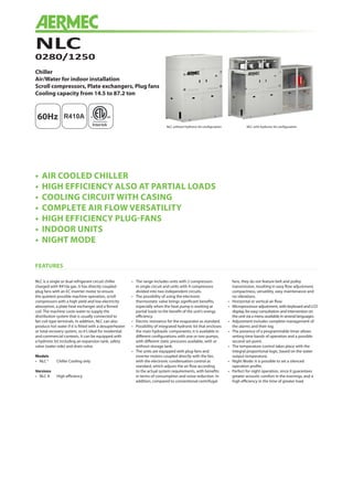
  • 1. NLC 0280/1250 Chiller Air/Water for indoor installation Scroll compressors, Plate exchangers, Plug fans Cooling capacity from 14.5 to 87.2 ton 60Hz • AIR COOLED CHILLER • HIGH EFFICIENCY ALSO AT PARTIAL LOADS • COOLING CIRCUIT WITH CASING • COMPLETE AIR FLOW VERSATILITY • HIGH EFFICIENCY PLUG-FANS • INDOOR UNITS • NIGHT MODE FEATURES NLC is a single or dual refrigerant circuit chiller charged with R410a gas. It has directly coupled plug fans with an EC inverter motor to ensure the quietest possible machine operation, scroll compressors with a high yield and low electricity absorption, a plate heat exchanger and a finned coil. The machine cools water to supply the distribution system that is usually connected to fan coil type terminals. In addition, NLC can also produce hot water if it is fitted with a desuperheater or total recovery system, so it’s ideal for residential and commercial contexts. It can be equipped with a hydronic kit including an expansion tank, safety valve (water side) and drain valve. Models • NLC ° Chiller Cooling only Versions • NLC A High efficiency • The range includes units with 2 compressors in single circuit and units with 4 compressors divided into two independent circuits. • The possibility of using the electronic thermostatic valve brings significant benefits, especially when the heat pump is working at partial loads to the benefit of the unit’s energy efficiency. • Electric resistance for the evaporator as standard. • Possibility of integrated hydronic kit that encloses the main hydraulic components; it is available in different configurations with one or two pumps, with different static pressures available, with or without storage tank. • The units are equipped with plug-fans and inverter motors coupled directly with the fan, with the electronic condensation control as standard, which adjusts the air flow according to the actual system requirements, with benefits in terms of consumption and noise reduction. In addition, compared to conventional centrifugal fans, they do not feature belt and pulley transmission, resulting in easy flow adjustment, compactness, versatility, easy maintenance and no vibrations. • Horizontal or vertical air flow. • Microprocessor adjustment, with keyboard and LCD display, for easy consultation and intervention on the unit via a menu available in several languages. • Adjustment includes complete management of the alarms and their log. • The presence of a programmable timer allows setting time bands of operation and a possible second set-point. • The temperature control takes place with the integral proportional logic, based on the water output temperature. • Night Mode: it is possible to set a silenced operation profile. • Perfect for night operation, since it guarantees greater acoustic comfort in the evenings, and a high efficiency in the time of greater load. NLC without hydronic kit configuration NLC with hydronic kit configuration
  • 2. UNIT CONFIGURATOR ACCESSORIES COMPATIBILITY n.a.: not available NLC 0280 0300 0330 0350 0550 0600 0650 0675 0750 0800 0900 1000 1100 1250 AER485P1 • • • • • • • • • • • • • • AERWEB300 • • • • • • • • • • • • • • PGD1 • • • • • • • • • • • • • • MULTICHILLER_UL • • • • • • • • • • • • • • AVX Refer to the technical manual VT FLG 1 1 1 1 2 (x2) 2 (x2) 2 (x2) 2 (x2) 1+2 (x2) 2 (x4) 2 (x4) 2 (x4) 2 (x4) 2 (x4) FL_UL • • • • • • • • • • • • • • FILTRO W DN50 DN50 DN50 DN50 DN65 DN65 DN65 DN65 DN65 DN80 DN80 DN80 DN80 DN80 ACCESSORIES MOUNTED IN THE FACTORY DRE • • • • • • • • • • • • • • RIFNLC 7 • • • • • • • • • • • • • • 6/8/9 n.a. n.a. n.a. n.a. n.a. n.a. n.a. n.a. n.a. n.a. n.a. n.a. n.a. n.a. KRQ • • • • • • • • • • • • • • CRATE 00 • • • • • • • • n.a. n.a. n.a. n.a. n.a. n.a. P1-P4 • • • • • • • • n.a. n.a. n.a. n.a. n.a. n.a. 01-04 • • • • • • • • n.a. n.a. n.a. n.a. n.a. n.a. ACCESSORIES ACCESSORIES: AER 485P1 RS-485 interface for supervising systems with MODBUS protocol. AERWEB300 AERWEB device allows the remote control of a chiller by means of a common PC through Ethernet connection, via a common browser; 4 models available: AERWEB300-6: Web server for monitoring and controlling maximum 6 RS485 network devices; AERWEB300-18: Web server for monitoring and controlling maximum 18 RS485 network devices; AERWEB300-6G: Web server for monitoring and controlling maximum 6 RS485 network devices with integrated GPRS modem; AERWEB300-18G: Web server for monitoring and controlling maximum 18 RS485 network devices with integrated GPRS modem; PGD1 Allows you to control the chiller at a distance. MULTICHILLER_UL Control, switch-on and switch-off system of the single chillers where multiple units are installed in parallel, always ensuring constant flow rate to the evaporators. AVX Spring anti-vibration mounts. VT Group of anti-vibration supports. FLG Flanges for ducts. FL_UL Flow switch. FILTRO W Water filter. Attention, the flow switch and the water filter must be mounted; failure to do so will void the warranty. ACCESSORIES MOUNTED IN THE FACTORY: DRE Plate peak current reduction electronic device. RIFNLC Current power factor correction. Connected in parallel to the motor, it allows a reduction of the input current (approx. 10%). KRQ Anti-condensate electric board resistance. CRATE Special wood cover for transport. FANS J Inverter fan POWER SUPPLY 6 230/3/60Hz with magnetic circuit breakers 7 460/3/60Hz with magnetic circuit breakers 8 575/3/60Hz with magnetic circuit breakers 9 208/3/60Hz with magnetic circuit breakers HYDRONIC KIT 00 Without hydronic kit 01 With storage tank and single low head pump 02 With storage tank and twin low head pumps (duty + standby) 03 With storage tank and single high head pump 04 With storage tank and twin high head pumps (duty + standby) P1 With single low head pump P2 With twin low head pumps (duty + standby) P3 With single high head pump P4 With twin high head pumps (duty + standby) NAME NLC SIZE 0280 - 0300 - 0330 - 0350 - 0550 - 0600 - 0650 - 0675 - 0750 - 0800 - 0900 - 1000 - 1100 - 1250 THERMOSTATIC VALVE ° Mechanical, standard operations (produced water down to +4 °C) Z Mechanical, low temperature operations (produced water range from 0 to +4 °C) Y Mechanical, low temperature operations (produced water range from -8 to +4 °C) X Electronic, standard operations (produced water down to +4 °C) MODELS ° Chiller cooling only HEATHING RECOVERY ° Without recovery D With desuperheater T With total recovery VERSION A High efficiency COILS ° Alluminium R Copper S Copper tin plated V Epoxy coated Options are not compatible: YD, YT, ZD, ZT, T with hydronic kit.
  • 3. TECHNICAL DATA NLC 0280 0300 0330 0350 0550 0600 0650 0675 0750 0800 0900 1000 1100 1250 Cooling capacity ton 14.5 18.8 21.2 23.5 28.7 36.7 40.7 44.0 51.6 56.5 64.7 73.0 80.2 87.2 Total input power kW 17.1 24.6 26.9 31.2 34.5 45.5 53.1 60.8 66.0 68.4 79.3 90.4 105.2 120.8 EER BTU/W 10.21 9.16 9.44 9.06 10.01 9.70 9.20 8.69 9.38 9.92 9.79 9.70 9.16 8.67 IPLV BTU/W 14.78 13.51 14.36 14.01 15.61 14.90 14.81 13.77 14.57 15.77 15.62 15.58 14.70 13.87 Water flow rate gpm 35 45 51 56 69 88 98 106 124 135 155 175 193 209 Total pressure drop without pump psi 2.4 2.8 3.7 4.1 2.3 2.9 3.0 3.5 3.7 3.6 3.5 3.9 4.6 5.0 ELECTRICAL DATA Power supply 230V/3~/60Hz Input current A 58 81 88 101 122 146 169 192 225 243 267 291 336 383 [LRA] A 240 299 360 371 445 619 719 739 569 619 793 811 931 971 [MCA] A 80 93 115 133 161 201 216 227 281 307 348 385 410 433 [MOP] A 107 126 166 184 216 275 301 312 337 363 422 458 495 518 Recom fuse A 100 125 150 175 200 250 300 300 300 350 400 450 450 500 Power supply 460V/3~/60Hz Input current A 27 38 41 47 57 68 79 90 105 113 124 136 156 178 [LRA] A 128 157 182 188 236 286 333 342 295 320 370 379 435 453 [MCA] A 42 54 59 64 84 94 108 120 140 159 168 176 202 225 [MOP] A 55 72 82 86 111 124 150 161 166 185 198 207 244 267 Recom fuse A 50 70 80 80 110 110 150 150 150 175 175 200 225 250 Power supply 575V/3~/60Hz Input current A 21 29 32 36 44 53 61 70 81 88 96 105 121 138 [LRA] A 100 105 134 138 176 228 286 292 222 242 293 300 365 379 [MCA] A 32 40 48 55 74 76 88 98 122 138 140 142 165 185 [MOP] A 42 52 68 75 97 100 123 133 145 162 165 167 200 220 Recom fuse A 40 50 60 75 90 100 110 125 125 150 150 150 200 200 Power supply 208V/3~/60Hz Input current A 64 90 97 112 135 162 187 213 248 269 295 322 371 424 [LRA] A 248 308 369 381 458 633 733 746 592 645 821 841 954 980 [MCA] A 84 97 120 138 167 208 222 233 286 312 353 389 415 438 [MOP] A 112 131 171 189 223 282 307 319 341 368 427 463 500 523 Recom fuse A 110 125 150 175 200 250 300 300 300 350 400 450 500 500 GENERAL DATA COMPRESSOR Compressor Type Scroll Scroll Scroll Scroll Scroll Scroll Scroll Scroll Scroll Scroll Scroll Scroll Scroll Scroll Compressor n° 2 2 2 2 2 2 2 2 4 4 4 4 4 4 Circuit n° 1 1 1 1 1 1 1 1 2 2 2 2 2 2 Refigerant gas Type R410A R410A R410A R410A R410A R410A R410A R410A R410A R410A R410A R410A R410A R410A EXCHANGER Exchanger Type Plate Plate Plate Plate Plate Plate Plate Plate Plate Plate Plate Plate Plate Plate Quantity n° 1 1 1 1 1 1 1 1 1 1 1 1 1 1 Min. water flow gpm 9.0 11.9 11.9 12.8 30.8 36.1 41.8 41.8 28.6 28.6 36.5 42.7 42.7 42.7 Max. water flow gpm 74.0 74.0 74.0 74.0 211.3 211.3 211.3 211.3 263.3 263.3 263.3 263.3 263.3 263.3 Water content gal 1.5 1.9 1.9 2.1 4.2 5.0 5.7 5.7 4.8 4.8 6.0 7.0 7.0 7.0 Water connection (in/out) ø 2 2 2 2 2½US 2”½US 2”½US 2”½US 2”½US 3 3 3 3 3 Crankcase heater n°/W 1/75 1/75 1/75 1/75 1/75 1/75 1/75 1/75 1/150 1/150 1/150 1/150 1/150 1/150 FANS Fans Type Plug fan Plug fan Plug fan Plug fan Plug fan Plug fan Plug fan Plug fan Plug fan Plug fan Plug fan Plug fan Plug fan Plug fan Numbers n° 2 2 2 2 4 4 4 4 6 8 8 8 8 8 Air flow rate cfm 7946 10418 9476 11124 18481 19835 21189 22307 30371 35844 36963 38611 40788 43496 High static pressure * in wg 1.6 1.0 1.4 0.5 1.6 1.6 0.9 0.5 0.6 1.6 1.6 1.6 1.0 0.6 SOUND DATA Sound power dB(A) 76.2 80.7 80.3 81.8 81.5 87.0 88.4 89.4 84.8 84.2 87.9 89.9 91.3 92.3 Sound pressure 10m/33ft dB(A) 44.5 48.9 48.5 50.1 49.6 55.2 56.6 57.6 52.9 52.1 55.8 57.9 59.2 60.3 COOLING MODE: AHRI CONDITION std 550/551 Evaporator water temperature (in/out): 12.26°C, 54.1°F / 6.67°C, 44.1°F - Dry bulb ambient air temperature: 35°C, 95°F * High static pressure calculated in the max external air temperature allowed. As the external air decreases, the high static pressure increases. (The data indicated can be modified at any time by Aermec if deemed necessary).
  • 4. All specifications are subject to change without prior notice. Although every effort has been made to ensure accuracy, Aermec does not assume responsibility or liability for eventual errors or omissions. Aermec S.p.A. Via Roma, 996 37040 Bevilacqua (VR) - Italy Tel. + 39 0442 633111 - Fax +39 0442 93577 NLC-CO_Y_NA60_02 DIMENSIONS AND WEIGHT NLC hydronic kit 0280 0300 0330 0350 0550 0600 0650 0675 0750 0800 0900 1000 1100 1250 Height 00 A in 86.7 86.7 86.7 86.7 86.7 86.7 86.7 86.7 86.7 86.7 86.7 86.7 86.7 86.7 Width 00 B in 69.0 69.0 69.0 69.0 124.1 124.1 124.1 124.1 193.1 248.2 248.2 248.2 248.2 248.2 Depth 00 C in 43.3 43.3 43.3 43.3 43.3 43.3 43.3 43.3 43.3 43.3 43.3 43.3 43.3 43.3 Weight 00 - lb 1592 1695 1744 1759 2857 3217 3340 3325 4314 5320 5692 6056 6363 6570 NLC hydronic kit 0280 0300 0330 0350 0550 0600 0650 0675 0750 0800 0900 1000 1100 1250 Height P1-P2-P3-P4 A in 86.7 86.7 86.7 86.7 86.7 86.7 86.7 86.7 86.7 86.7 86.7 86.7 86.7 86.7 Width P1-P2-P3-P4 B in 98.5 98.5 98.5 98.5 124.1 124.1 124.1 124.1 193.1 248.2 248.2 248.2 248.2 248.2 Depth P1-P2-P3-P4 C in 43.3 43.3 43.3 43.3 43.3 43.3 43.3 43.3 43.3 43.3 43.3 43.3 43.3 43.3 NLC hydronic kit 0280 0300 0330 0350 0550 0600 0650 0675 0750 0800 0900 1000 1100 1250 Height 01-02-03-04 A in 86.7 86.7 86.7 86.7 86.7 86.7 86.7 86.7 86.7 86.7 86.7 86.7 86.7 86.7 Width 01-02-03-04 B in 134.0 134.0 134.0 134.0 163.5 163.5 163.5 163.5 232.5 287.6 287.6 287.6 287.6 287.6 Depth 01-02-03-04 C in 43.3 43.3 43.3 43.3 43.3 43.3 43.3 43.3 43.3 43.3 43.3 43.3 43.3 43.3 NLC heathing recovery 0280 0300 0330 0350 0550 0600 0650 0675 0750 0800 0900 1000 1100 1250 Height T A in 86.7 86.7 86.7 86.7 86.7 86.7 86.7 86.7 86.7 86.7 86.7 86.7 86.7 86.7 Width T B in 69.0 69.0 69.0 69.0 124.1 124.1 124.1 124.1 193.1 248.2 248.2 248.2 248.2 248.2 Depth T C in 43.3 43.3 43.3 43.3 43.3 43.3 43.3 43.3 43.3 43.3 43.3 43.3 43.3 43.3 The designs are representative of some structural work, more information is available in the technical documentation A C B A C B