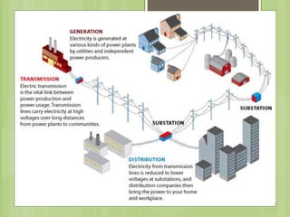
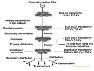
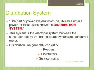
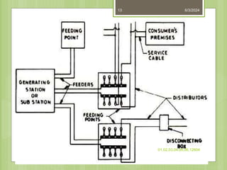
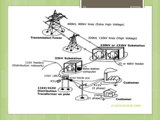
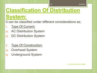
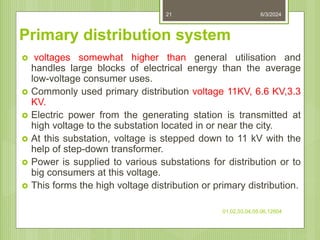
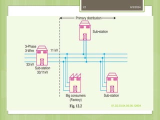
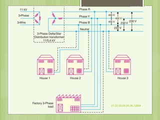
NSTI V HYDERABAD
NAME AKASH SHARMA
COURSE CITS ELECTRICIAN
BATCH 2
ADM NO 6660
6/3/2024
01,02,03,04,05,06,12604
1
6/3/2024
01,02,03,04,05,06,12604
2
BY
6/3/2024
01,02,03,04,05,06,12604
3
6/3/2024
01,02,03,04,05,06,12604
4
6/3/2024
01,02,03,04,05,06,12604
5
Contents To Be Covered:
 Definition
 Classification Of Distribution System
 Distribution System Losses
6/3/2024
01,02,03,04,05,06,12604
6
Distribution System
 “The part of power system which distributes electrical
power for local use is known as DISTRIBUTION
SYSTEM.”
 This system is the electrical system between the
substation fed by the transmission system and consumer
meter.
 Distribution line generally consist of
 Feeders
 Distributers
 Service mains
6/3/2024
01,02,03,04,05,06,12604
7
FEEDERS DISTRIBUTORS SERVICE MAINS
Distribution
6/3/2024
01,02,03,04,05,06,12604
8
Feeder
 A Feeder is conductor which connects the
substation to the area where power is to be
distributed .
 Feeder are used to feed the electrical power from
the generating station to the substation
 No tapings are taken from the feeder
 So the current in it remains the same throughout
 Main consideration in the design of feeder is the
Current carrying capacity.
6/3/2024
01,02,03,04,05,06,12604
9
Distributer
 A distributer is a conductor from which tapings
are taken from pole mounted transformer to
the consumer
 The current through a distributer is not
constant because tapings are taken at various
places along its length
 Voltage drop is main consideration
 Limit of variation is 6% of rated at consumer
6/3/2024
01,02,03,04,05,06,12604
10
Service mains
 A service mains is a generally a small cable
which connects the distributer to the
consumer ‘s meter.
 The connecting links between the distributor
and the consumer terminals.
6/3/2024
01,02,03,04,05,06,12604
11
6/3/2024
01,02,03,04,05,06,12604
12
6/3/2024
01,02,03,04,05,06,12604
13
6/3/2024
01,02,03,04,05,06,12604
14
6/3/2024
01,02,03,04,05,06,12604
15
6/3/2024
01,02,03,04,05,06,12604
16
Introduction:
 Distribution system is a part of power system, existing
between distribution substations and consumers.
 It is further classified on the basis of voltage
 Primary distribution system- 11 KV or 6.6 KV or 3.3 KV
 Secondary distribution system- 415 V or 230 V
6/3/2024
01,02,03,04,05,06,12604
17
Classification Of Distribution
System:
It can be classified under different considerations as;
1. Type Of Current:
a) AC Distribution System
b) DC Distribution System
2. Type Of Construction:
a) Overhead System
b) Underground System
6/3/2024
01,02,03,04,05,06,12604
18
3. Type Of Service:
a) General Lighting & Power
b) Industrial Power
c) Railway
d) Streetlight etc
4. Number Of Wires:
a) Two Wire
b) Three Wire
c) Four Wire
5. Scheme Of Connection:
a) Radial Distribution System
b) Ring or Loop Distribution System
c) Interconnected Distribution System
6/3/2024
01,02,03,04,05,06,12604
19
Ac distribution
 A.c. distribution system is the electrical
system between the step-down substation fed
by the transmission system and the
consumers’ meters. The a.c. distribution
system is classified into
 ( i) primary distribution system and
 ( ii) secondary distribution system.
6/3/2024
01,02,03,04,05,06,12604
20
Primary distribution system
 voltages somewhat higher than general utilisation and
handles large blocks of electrical energy than the average
low-voltage consumer uses.
 Commonly used primary distribution voltage 11KV, 6.6 KV,3.3
KV.
 Electric power from the generating station is transmitted at
high voltage to the substation located in or near the city.
 At this substation, voltage is stepped down to 11 kV with the
help of step-down transformer.
 Power is supplied to various substations for distribution or to
big consumers at this voltage.
 This forms the high voltage distribution or primary distribution.
6/3/2024
01,02,03,04,05,06,12604
21
6/3/2024
01,02,03,04,05,06,12604
22
Secondary distribution system.
 It is that part of a.c. distribution system which
includes the range of voltages at which the
ultimate consumer utilizes the electrical
energy delivered to him.
 The secondary distribution employs 400/230
V, 3-phase, 4-wire system.
6/3/2024
01,02,03,04,05,06,12604
23
6/3/2024
01,02,03,04,05,06,12604
24
D.C. Distribution
 D.c. supply is required for the operation of
variable speed machinery ( i.e., d.c. motors), for
electro-chemical work and for congested areas
where storage battery reserves are necessary.
 For this purpose, a.c. power is converted into d.c.
power at the substation by using converting
machinery e.g., mercury arc rectifiers, and motor-
generator sets. The d.c. supply from the
substation may be obtained in the form of
6/3/2024
01,02,03,04,05,06,12604
25
Type of DC distributor
 The dc supply from the substation may be
obtained in form of
 ( i) 2-wire or
 ( ii) 3-wire for distribution.
6/3/2024
01,02,03,04,05,06,12604
26
2 wire 3 wire
6/3/2024
01,02,03,04,05,06,12604
27
6/3/2024
01,02,03,04,05,06,12604
28
 Two outer and a middle or neutral wire is earthed at
the s/s.
 Voltage between the outer is twice the voltage
between either outer and neutral wire.
 Advantage – available two voltage at the consumer
terminal.
 Loads requiring high voltage connected across the
outers.
 Lamps and heating circuits requiring less voltage are
connected between either outer and neutral.
Method of obtaining 3 wire D.c system
 Two generator method.
 3-wire D.c. generator.
 Balancer set
6/3/2024
01,02,03,04,05,06,12604
29
Two generator method
6/3/2024
01,02,03,04,05,06,12604
30
Two generator method
 D.c generator G1 and G2 are connected in
series and the neutral is obtained from the
common point btwn generator
 G1 supplies a I1, G2 supplies a I2
 Difference of load current on both side (I1-I2)
flow through the neutral wire.
 Disad.:two separate generator are required.
6/3/2024
01,02,03,04,05,06,12604
31
3-wire D.c. generator.
6/3/2024
01,02,03,04,05,06,12604
32
3-wire D.c. generator.
 Consist of a standard 2 wire machine with one
or two coils of high reactance and low
resistance that connected to opposite points
of the armature winding.
 Neutral wire is obtained from common point.
6/3/2024
01,02,03,04,05,06,12604
33
Connection schemes of
distribution system
 Radial system
 Ring main system
 Interconnected system
6/3/2024
01,02,03,04,05,06,12604
34
Radial Distribution System:
 separate feeders radiate from a single substation and feed the
distributors at one end only.
 Only one path is connected between each customer and substation.
 Electrical power flows along a single path.
 If interrupted, results in complete loss of power to the customer.
Advantages:
 Low cost .
 Simple planning.
Disadvantages :
 The radial system is employed only when power is generated at low
voltage and the substation is located at the centre of the load.
 Distributor nearer to feeding end is heavily loaded.
 Consumers at far end of feeder would be subjected to serious
voltage fluctuations.
6/3/2024
01,02,03,04,05,06,12604
35
6/3/2024
01,02,03,04,05,06,12604
36
6/3/2024
01,02,03,04,05,06,12604
37
Ring or Loop Distribution
System:
 It consists of two or more paths between
power sources and the customer.
 The loop circuit starts from the substation
bus-bars, makes a loop through the area to
be served, and returns to the substation
Advantages:
 Less conductor material is required.
 Less voltage fluctuations.
 More reliable.
Disadvantages:
 It is difficult to design as compared to the
design of radial system.
6/3/2024
01,02,03,04,05,06,12604
38
6/3/2024
01,02,03,04,05,06,12604
39
Interconnected Distribution System:
 It is supplied by a number of feeders.
 Radial primary feeders can be tapped off from the
interconnecting tie feeders.
 They can also serve directly from the substation.
Advantages:
 Increases the reliability of supply
 Losses are less
 Quality of service is improved.
Disadvantages:
 Its initial cost is more.
 Difficult in planning, design and operation.
6/3/2024
01,02,03,04,05,06,12604
40
6/3/2024
01,02,03,04,05,06,12604
41
6/3/2024
01,02,03,04,05,06,12604
42
6/3/2024
01,02,03,04,05,06,12604
43
D.C. Distribution
 D.c. supply is required for the operation of variable
speed machinery ( i.e., d.c. motors),
 for electro-chemical work and for congested areas where
storage battery reserves are necessary.
 For this purpose, a.c. power is converted into d.c. power
at the substation by using converting machinery e.g.,
mercury arc rectifiers, rotary converters and motor-
generator sets. The d.c. supply from the substation may
be obtained in the form of
6/3/2024
01,02,03,04,05,06,12604
44
DC Distribution:
 Voltage drop along distributor is considered as a main
factor while designing a distributor.
 It depends upon the nature of load and also on feeding,
whether it is fed at one or both ends.
According to loading, a distributor can be classified as:
i. Fed at one end.
ii. Fed at both ends. a). With equal voltages.
b). With unequal voltages.
iii. Fed at centre.
iv. Ring mains.
6/3/2024
01,02,03,04,05,06,12604
45
DC Distribution Feed at one end
6/3/2024
01,02,03,04,05,06,12604
46
 a) The current in the various sections of the distributor
away from feeding point goes on decreasing. Thus
current in section AC is more than the current in section
CD and current in section CD is more than the current in
section DE.
 (b) The voltage across the loads away from the feeding
point goes on decreasing. Thus in Fig. 13.1, the
minimum voltage occurs at the load point E.
 (c) In case a fault occurs on any section of the
distributor, the whole distributor will have to be
disconnected from the supply mains. Therefore,
continuity of supply is interrupted
6/3/2024
01,02,03,04,05,06,12604
47
Distributor fed at center
6/3/2024
01,02,03,04,05,06,12604
48
 In this type of feeding, the distributor is connected to the
supply mains at both ends and loads are tapped off at
different points along the length of the distributor.
 The voltage at the feeding points may or may not be
equal. distributor A B fed at the ends A and B and loads
of I1, I2 and I3 tapped off at points C respectively.
 Here, the load voltage goes on decreasing as we move
away from one feeding point say A , reaches minimum
value and then again starts rising and reaches maximum
value when we reach the other feeding point B.
 The minimum voltage occurs at some load point and is
never fixed. It is shifted with the variation of load on
different sections of the distributor.
6/3/2024
01,02,03,04,05,06,12604
49
Advantages
 (a) If a fault occurs on any feeding point of the
distributor, the continuity of supply is main-
tained from the other feeding point.
 (b) In case of fault on any section of the
distributor, the continuity of supply is
maintained from the other feeding point.
 (C)The area of X-section required for a doubly
fed distributor is much less than that of a
singly fed distributor.
6/3/2024
01,02,03,04,05,06,12604
50
Ring Distributor
6/3/2024
01,02,03,04,05,06,12604
51
6/3/2024
01,02,03,04,05,06,12604
52
 In this type of feeding, the centre of the distributor is
connected to the supply mains as shown in Fig.
 It is equivalent to two singly fed distributors, each
distributor having a common feeding point and
length equal to half of the total length
6/3/2024
53
01,02,03,04,05,06,12604

electricaldistributionsystemelectricaldistributionsystem.pptx

  • 1.
    NSTI V HYDERABAD NAMEAKASH SHARMA COURSE CITS ELECTRICIAN BATCH 2 ADM NO 6660 6/3/2024 01,02,03,04,05,06,12604 1
  • 2.
  • 3.
  • 4.
  • 5.
  • 6.
    Contents To BeCovered:  Definition  Classification Of Distribution System  Distribution System Losses 6/3/2024 01,02,03,04,05,06,12604 6
  • 7.
    Distribution System  “Thepart of power system which distributes electrical power for local use is known as DISTRIBUTION SYSTEM.”  This system is the electrical system between the substation fed by the transmission system and consumer meter.  Distribution line generally consist of  Feeders  Distributers  Service mains 6/3/2024 01,02,03,04,05,06,12604 7
  • 8.
    FEEDERS DISTRIBUTORS SERVICEMAINS Distribution 6/3/2024 01,02,03,04,05,06,12604 8
  • 9.
    Feeder  A Feederis conductor which connects the substation to the area where power is to be distributed .  Feeder are used to feed the electrical power from the generating station to the substation  No tapings are taken from the feeder  So the current in it remains the same throughout  Main consideration in the design of feeder is the Current carrying capacity. 6/3/2024 01,02,03,04,05,06,12604 9
  • 10.
    Distributer  A distributeris a conductor from which tapings are taken from pole mounted transformer to the consumer  The current through a distributer is not constant because tapings are taken at various places along its length  Voltage drop is main consideration  Limit of variation is 6% of rated at consumer 6/3/2024 01,02,03,04,05,06,12604 10
  • 11.
    Service mains  Aservice mains is a generally a small cable which connects the distributer to the consumer ‘s meter.  The connecting links between the distributor and the consumer terminals. 6/3/2024 01,02,03,04,05,06,12604 11
  • 12.
  • 13.
  • 14.
  • 15.
  • 16.
  • 17.
    Introduction:  Distribution systemis a part of power system, existing between distribution substations and consumers.  It is further classified on the basis of voltage  Primary distribution system- 11 KV or 6.6 KV or 3.3 KV  Secondary distribution system- 415 V or 230 V 6/3/2024 01,02,03,04,05,06,12604 17
  • 18.
    Classification Of Distribution System: Itcan be classified under different considerations as; 1. Type Of Current: a) AC Distribution System b) DC Distribution System 2. Type Of Construction: a) Overhead System b) Underground System 6/3/2024 01,02,03,04,05,06,12604 18
  • 19.
    3. Type OfService: a) General Lighting & Power b) Industrial Power c) Railway d) Streetlight etc 4. Number Of Wires: a) Two Wire b) Three Wire c) Four Wire 5. Scheme Of Connection: a) Radial Distribution System b) Ring or Loop Distribution System c) Interconnected Distribution System 6/3/2024 01,02,03,04,05,06,12604 19
  • 20.
    Ac distribution  A.c.distribution system is the electrical system between the step-down substation fed by the transmission system and the consumers’ meters. The a.c. distribution system is classified into  ( i) primary distribution system and  ( ii) secondary distribution system. 6/3/2024 01,02,03,04,05,06,12604 20
  • 21.
    Primary distribution system voltages somewhat higher than general utilisation and handles large blocks of electrical energy than the average low-voltage consumer uses.  Commonly used primary distribution voltage 11KV, 6.6 KV,3.3 KV.  Electric power from the generating station is transmitted at high voltage to the substation located in or near the city.  At this substation, voltage is stepped down to 11 kV with the help of step-down transformer.  Power is supplied to various substations for distribution or to big consumers at this voltage.  This forms the high voltage distribution or primary distribution. 6/3/2024 01,02,03,04,05,06,12604 21
  • 22.
  • 23.
    Secondary distribution system. It is that part of a.c. distribution system which includes the range of voltages at which the ultimate consumer utilizes the electrical energy delivered to him.  The secondary distribution employs 400/230 V, 3-phase, 4-wire system. 6/3/2024 01,02,03,04,05,06,12604 23
  • 24.
  • 25.
    D.C. Distribution  D.c.supply is required for the operation of variable speed machinery ( i.e., d.c. motors), for electro-chemical work and for congested areas where storage battery reserves are necessary.  For this purpose, a.c. power is converted into d.c. power at the substation by using converting machinery e.g., mercury arc rectifiers, and motor- generator sets. The d.c. supply from the substation may be obtained in the form of 6/3/2024 01,02,03,04,05,06,12604 25
  • 26.
    Type of DCdistributor  The dc supply from the substation may be obtained in form of  ( i) 2-wire or  ( ii) 3-wire for distribution. 6/3/2024 01,02,03,04,05,06,12604 26
  • 27.
    2 wire 3wire 6/3/2024 01,02,03,04,05,06,12604 27
  • 28.
    6/3/2024 01,02,03,04,05,06,12604 28  Two outerand a middle or neutral wire is earthed at the s/s.  Voltage between the outer is twice the voltage between either outer and neutral wire.  Advantage – available two voltage at the consumer terminal.  Loads requiring high voltage connected across the outers.  Lamps and heating circuits requiring less voltage are connected between either outer and neutral.
  • 29.
    Method of obtaining3 wire D.c system  Two generator method.  3-wire D.c. generator.  Balancer set 6/3/2024 01,02,03,04,05,06,12604 29
  • 30.
  • 31.
    Two generator method D.c generator G1 and G2 are connected in series and the neutral is obtained from the common point btwn generator  G1 supplies a I1, G2 supplies a I2  Difference of load current on both side (I1-I2) flow through the neutral wire.  Disad.:two separate generator are required. 6/3/2024 01,02,03,04,05,06,12604 31
  • 32.
  • 33.
    3-wire D.c. generator. Consist of a standard 2 wire machine with one or two coils of high reactance and low resistance that connected to opposite points of the armature winding.  Neutral wire is obtained from common point. 6/3/2024 01,02,03,04,05,06,12604 33
  • 34.
    Connection schemes of distributionsystem  Radial system  Ring main system  Interconnected system 6/3/2024 01,02,03,04,05,06,12604 34
  • 35.
    Radial Distribution System: separate feeders radiate from a single substation and feed the distributors at one end only.  Only one path is connected between each customer and substation.  Electrical power flows along a single path.  If interrupted, results in complete loss of power to the customer. Advantages:  Low cost .  Simple planning. Disadvantages :  The radial system is employed only when power is generated at low voltage and the substation is located at the centre of the load.  Distributor nearer to feeding end is heavily loaded.  Consumers at far end of feeder would be subjected to serious voltage fluctuations. 6/3/2024 01,02,03,04,05,06,12604 35
  • 36.
  • 37.
  • 38.
    Ring or LoopDistribution System:  It consists of two or more paths between power sources and the customer.  The loop circuit starts from the substation bus-bars, makes a loop through the area to be served, and returns to the substation Advantages:  Less conductor material is required.  Less voltage fluctuations.  More reliable. Disadvantages:  It is difficult to design as compared to the design of radial system. 6/3/2024 01,02,03,04,05,06,12604 38
  • 39.
  • 40.
    Interconnected Distribution System: It is supplied by a number of feeders.  Radial primary feeders can be tapped off from the interconnecting tie feeders.  They can also serve directly from the substation. Advantages:  Increases the reliability of supply  Losses are less  Quality of service is improved. Disadvantages:  Its initial cost is more.  Difficult in planning, design and operation. 6/3/2024 01,02,03,04,05,06,12604 40
  • 41.
  • 42.
  • 43.
  • 44.
    D.C. Distribution  D.c.supply is required for the operation of variable speed machinery ( i.e., d.c. motors),  for electro-chemical work and for congested areas where storage battery reserves are necessary.  For this purpose, a.c. power is converted into d.c. power at the substation by using converting machinery e.g., mercury arc rectifiers, rotary converters and motor- generator sets. The d.c. supply from the substation may be obtained in the form of 6/3/2024 01,02,03,04,05,06,12604 44
  • 45.
    DC Distribution:  Voltagedrop along distributor is considered as a main factor while designing a distributor.  It depends upon the nature of load and also on feeding, whether it is fed at one or both ends. According to loading, a distributor can be classified as: i. Fed at one end. ii. Fed at both ends. a). With equal voltages. b). With unequal voltages. iii. Fed at centre. iv. Ring mains. 6/3/2024 01,02,03,04,05,06,12604 45
  • 46.
    DC Distribution Feedat one end 6/3/2024 01,02,03,04,05,06,12604 46
  • 47.
     a) Thecurrent in the various sections of the distributor away from feeding point goes on decreasing. Thus current in section AC is more than the current in section CD and current in section CD is more than the current in section DE.  (b) The voltage across the loads away from the feeding point goes on decreasing. Thus in Fig. 13.1, the minimum voltage occurs at the load point E.  (c) In case a fault occurs on any section of the distributor, the whole distributor will have to be disconnected from the supply mains. Therefore, continuity of supply is interrupted 6/3/2024 01,02,03,04,05,06,12604 47
  • 48.
    Distributor fed atcenter 6/3/2024 01,02,03,04,05,06,12604 48
  • 49.
     In thistype of feeding, the distributor is connected to the supply mains at both ends and loads are tapped off at different points along the length of the distributor.  The voltage at the feeding points may or may not be equal. distributor A B fed at the ends A and B and loads of I1, I2 and I3 tapped off at points C respectively.  Here, the load voltage goes on decreasing as we move away from one feeding point say A , reaches minimum value and then again starts rising and reaches maximum value when we reach the other feeding point B.  The minimum voltage occurs at some load point and is never fixed. It is shifted with the variation of load on different sections of the distributor. 6/3/2024 01,02,03,04,05,06,12604 49
  • 50.
    Advantages  (a) Ifa fault occurs on any feeding point of the distributor, the continuity of supply is main- tained from the other feeding point.  (b) In case of fault on any section of the distributor, the continuity of supply is maintained from the other feeding point.  (C)The area of X-section required for a doubly fed distributor is much less than that of a singly fed distributor. 6/3/2024 01,02,03,04,05,06,12604 50
  • 51.
  • 52.
    6/3/2024 01,02,03,04,05,06,12604 52  In thistype of feeding, the centre of the distributor is connected to the supply mains as shown in Fig.  It is equivalent to two singly fed distributors, each distributor having a common feeding point and length equal to half of the total length
  • 53.