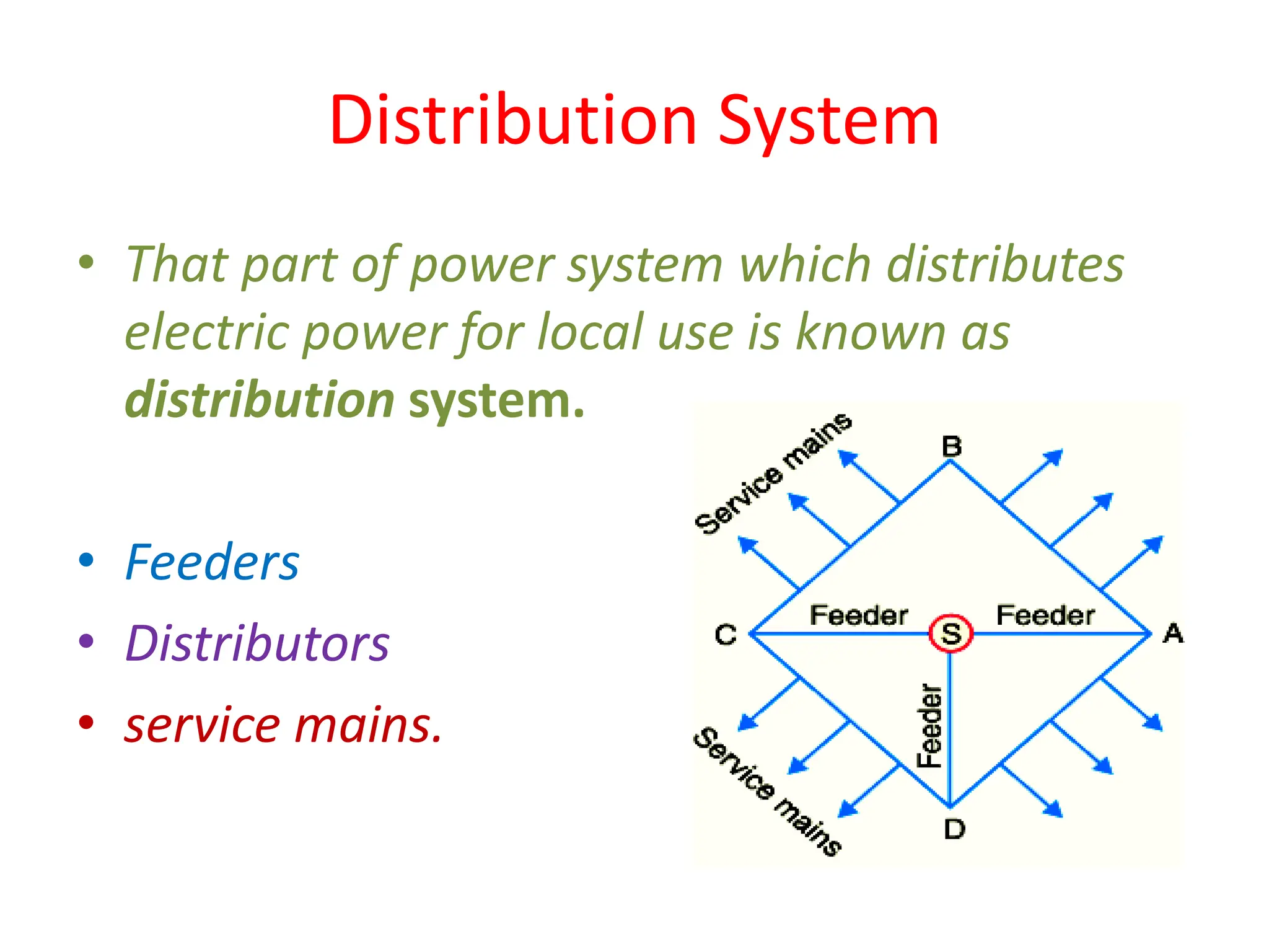
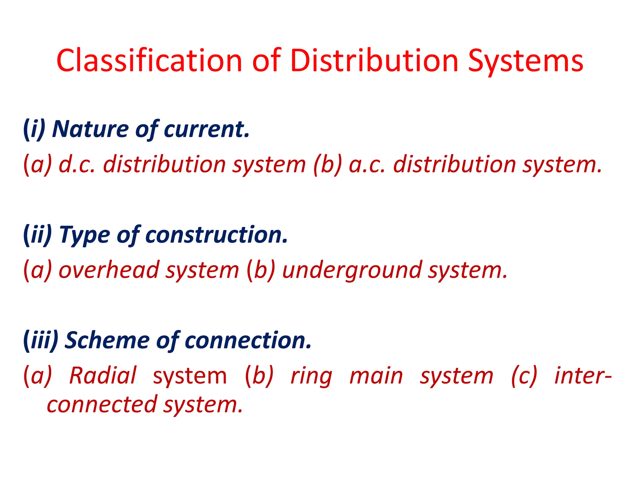
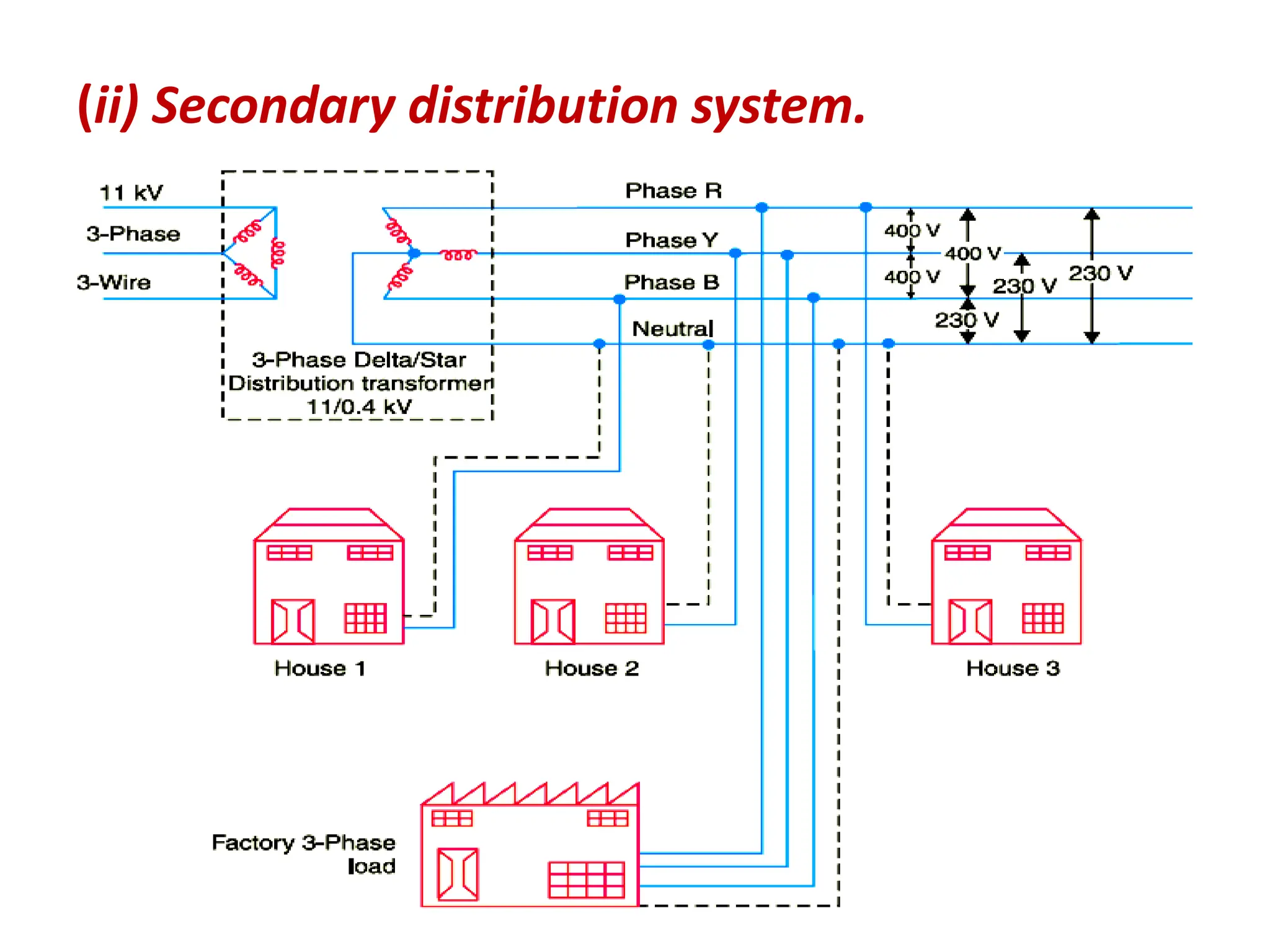
2. Distribution System
• That part of power system which distributes
electric power for local use is known as
distribution system.
• Feeders
• Distributors
• service mains.
3. Classification of Distribution Systems
(i) Nature of current.
(a) d.c. distribution system (b) a.c. distribution system.
(ii) Type of construction.
(a) overhead system (b) underground system.
(iii) Scheme of connection.
(a) Radial system (b) ring main system (c) inter-
connected system.
9. (ii) Ring main system.
The ring main system has the following advantages :
(a) There are less voltage fluctuations at consumer’s terminals.
(b) The system is very reliable as each distributor is fed via *two
feeders.
10.
11. (iii) Interconnected system.
The interconnected system has the following advantages :
(a) It increases the service reliability.
(b) Any area fed from one generating station during peak load hours can be
fed from the other generating station. This reduces reserve power
capacity and increases efficiency of the system.
12. Types of D.C. Distributors
(i) Distributor fed at one end.
(a) The current in the various sections of the distributor away from
feeding point goes on decreasing.
(b) The voltage across the loads away from the feeding point goes on
decreasing.
(c) In case a fault occurs on any section of the distributor, the whole
distributor will have to be disconnected from the supply mains.
Therefore, continuity of supply is interrupted.
13. • A 2-wire d.c. distributor cable AB is 2 km long and
supplies loads of 100A, 150A, 200A and 50A situated
500 m, 1000 m, 1600 m and 2000 m from the feeding
point A. Each conductor has a resistance of 0.01 Ω
per 1000 m. Calculate the p.d. at each load point if a
p.d. of 300 V is maintained at point A.
16. Uniformly Loaded Distributor Fed at One End
Fig shows the single line diagram of a 2-wire d.c. distributor AB fed at one end A
and loaded uniformly with i amperes per metre length. It means that at every 1 m
length of the distributor, the load tapped is i amperes. Let l metres be the length of
the distributor and r ohm be the resistance per metre run.
Consider a point C on the distributor at a distance x metres from the feeding point
A as shown in Fig. Then current at point C is
= i l − i x amperes = i (l − x) amperes
18. Uniformly Loaded Distributor Fed at One End
A 2-wire d.c. distributor 200 metres long is uniformly loaded with
2A/metre. Resistance of single wire is 0·3 Ω/km. If the distributor is
fed at one end, calculate :
(i) the voltage drop up to a distance of 150 m from the feeding point
(ii) the maximum voltage drop
20. (ii) Distributor fed at both ends.
Advantages
(a) If a fault occurs on any feeding point of the distributor, the
continuity of supply is maintained from the other feeding point.
(b) In case of fault on any section of the distributor, the continuity of
supply is maintained from the other feeding point.
(c) The area of X-section required for a doubly fed distributor is much
less than that of a singly fed distributor.
21. A 2-wire d.c. street mains AB, 600 m long is fed from both
ends at 220 V. Loads of 20 A, 40 A, 50 A and 30 A are
tapped at distances of 100m, 250m, 400m and 500 m from
the end A respectively. If the area of X-section of
distributor conductor is 1cm2, find the minimum
consumer voltage. Take ρ = 1·7 × 10−6 Ω cm.
22.
23. A 2-wire d.c. distributor AB is fed from both ends. At feeding
point A, the voltage is maintained as at 230 V and at B 235 V.
The total length of the distributor is 200 metres and loads are
tapped off as under :
25 A at 50 metres from A ; 50 A at 75 metres from A
30 A at 100 metres from A ; 40 A at 150 metres from A
The resistance per kilometre of one conductor is 0·3 Ω.
Calculate :
(i) currents in various sections of the distributor
(ii) minimum voltage and the point at which it occurs
24. Ring Distributor
• A distributor arranged to form a closed loop
and fed at one or more points is called a ring
distributor.
• For the purpose of calculating voltage
distribution, the distributor can be considered
as consisting of a series of open distributors
fed at both ends.
25. • A 2-wire d.c. distributor ABCDEA in the form of a ring
main is fed at point A at 220 V and is loaded as under :
• 10A at B ; 20A at C ; 30A at D and 10 A at E.
• The resistances of various sections (go and return) are :
AB = 0·1 Ω ; BC = 0·05 Ω ; CD = 0·01 Ω ; DE = 0·025
Ω and EA = 0·075 Ω. Determine :
(i) the point of minimum potential
(ii) current in each section of distributor
26.
27. Ring Main Distributor with
Interconnector
• In order to reduce voltage drops in various
sections, distant points of the distributor are
joined through a conductor called
interconnector.
• The points B and D of the ring distributor are
joined through an interconnector BD.
However, the solution of such a network can
be readily obtained by applying Thevenin’s
theorem.
28.
29. A d.c. ring main ABCDA is fed from point A from a
250 V supply and the resistances (including both
lead and return) of various sections are as follows
: AB = 0·02 Ω ; BC = 0·018 Ω ; CD = 0·025 Ω and DA
= 0·02 Ω. The main supplies loads of 150 A at B ;
300 A at C and 250 A at D. Determine the voltage
at each load point. If the points A and C are linked
through an interconnector of resistance 0·02 Ω,
determine the new voltage at each load point.
30.
31. A.C. Distribution
A.C. distribution calculations differ from those of d.c. distribution in
the following respects :
(i) In case of d.c. system, the voltage drop is due to resistance
alone. However, in a.c. system, the voltage drops are due to the
combined effects of resistance, inductance and capacitance.
(ii) In a d.c. system, additions and subtractions of currents or
voltages are done arithmetically but in case of a.c. system, these
operations are done vectorially.
(iii) In an a.c. system, power factor (p.f.) has to be taken into
account. Loads tapped off form the distributor are generally at
different power factors. There are two ways of referring power
factor viz
(a) It may be referred to supply or receiving end voltage which is
regarded as the reference vector.
(b) It may be referred to the voltage at the load point itself.
32. Methods of Solving A.C. Distribution Problems
(i) Power factors referred to receiving end voltage.
33. Methods of Solving A.C. Distribution Problems
(i) Power factors referred to receiving end voltage.
34. Methods of Solving A.C. Distribution Problems
(i) Power factors referred to receiving end voltage.
39. Four-Wire Star-Connected Unbalanced Loads
The following points may be noted carefully :
(i) Since the neutral wire has negligible resistance, supply neutral N and load
neutral N′ will be at the same potential. It means that voltage across
each impedance is equal to the phase voltage of the supply. However,
current in each phase (or line) will be different due to unequal
impedances.
(ii) The amount of current flowing in the neutral wire will depend upon the
magnitudes of line currents and their phasor relations. In most circuits
encountered in practice, the neutral current is equal to or smaller than
one of the line currents.
40. A single phase a.c. distributor AB 300 metres long is fed from end A
and is loaded as under :
(i) 100 A at 0·707 p.f. lagging 200 m from point A
(ii) 200 A at 0·8 p.f. lagging 300 m from point A
The load resistance and reactance of the distributor is 0·2 Ω and 0·1
Ω per kilometre. Calculate the total voltage drop in the distributor.
The load power factors refer to the voltage at the far end.