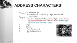
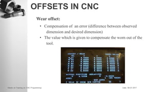
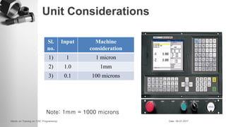
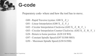
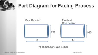
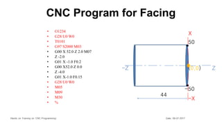
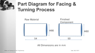
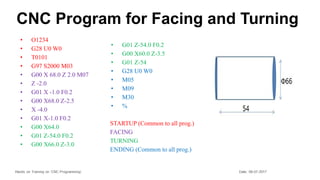
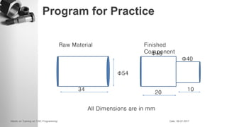
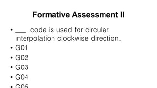
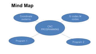
CNC Programming
Hands on Training on ‘CNC Programming’ Date: 08-07-2017
Presented by
Mohamed Ismail A
Assistant Professor
Mechatronics
Alpha Breathing
2
Breath In
Breath Out
Learning through evocation
3
CNC Programming
4
General Objective
5
To Create CNC programming for the part diagram
Specific Objectives
6
Students will able to
SO 1: List the types of controllers used in machines .
(E) (R-F).
SO 2: generate the CNC program for the given part
diagram . ( E) (Cr-C).
7
Taxonomy of Objectives
Knowledge Dimension The Cognitive Process Dimension
Remember Understand Apply Analyse Evaluate Create
A. Factual Knowledge
1
B. Conceptual Knowledge
2
C. Procedural Knowledge
D. Meta Cognitive
Knowledge
Pre requisite
8
1.Basic workshop Laboratory.
2.Manufacturing technology
❖ Coordinate systems.
❖ Address Characters.
❖ Offsets.
❖ Unit Considerations.
❖ G-codes.
❖ M-codes.
❖ Simple Programming.
Contents
Coordinate system
❑ Numbers which indicate the location of a point relative to
a fixed reference point (the origin).
Types of Coordinate System
❖ Absolute Method
❖ Incremental Method
Absolute method
Uses X, Y, and sometimes a Z-axis to establish a point
some distance from a common Reference point (origin)
Examples:
10
30
40
Incremental method
Point at some distance is established from its Previous
point(origin).
In this case reference point not common.
Example:
10
20
10
Two Axes CNC
Z – Horizontal
X - Vertical
Point Establishment in Absolute
Method
points axes
Z X
p1 0 0
p2 20 0
p3 20 5
p4 10 5
p5 10 20
p6 0 20
Take p1 as reference point
Point Establishment in Incremental
Method
points axes
Z X
p1 0 -20
p2 20 0
p3 0 5
p4 -10 0
p5 0 15
p6 -10 0
Point Establishment in Incremental
Method
points axes
Z X
p1 -10 0
p2 0 15
p3 -10 0
p4 0 -20
p5 20 0
p6 0 5
ADDRESS CHARACTERS
O _ _ _ _ Program Name
It must start with ‘O’ followed by 4 digits 0000 to 9999
T_ _ _ _ Tool number
It must be start with ‘T’ followed by four digits whereas first two
digit represents tool number (01 to 12) and the next two digit
represents offset number (01 to 64)
A Angle
R Radius
F Feed Rate(mm/rev)
S Spindle Speed (rpm)
OFFSETS IN CNC
Offset - compensation of something
Geometry offset:
difference between machine’s(Tool) reference point and
work’s reference point
OFFSETS IN CNC
Wear offset:
• Compensation of an error (difference between observed
dimension and desired dimension)
• The value which is given to compensate the worn out of the
tool.
Unit Considerations
Sl.
no.
Input Machine
consideration
1) 1 1 micron
2) 1.0 1mm
3) 0.1 100 microns
Note: 1mm = 1000 microns
G-code
Preparatory code- where and how the tool has to move.
G00 - Rapid Traverse (syntax: G00 X_ Z_)
G01 - Linear Interpolation (G00 X_ Z_ F_)
G02 - Circular Interpolation Clockwise (G02 X_ Z_ R_ F_ )
G03 - Circular Interpolation Counter Clockwise. (G02 X_ Z_ R_ F_ )
G28 - Return to home position (G28 U0 W0)
G97 - Constant Spindle Speed (G97 S1500 M03)
G50 - Maximum Spindle Speed (G50 S1500)
M-code
Miscellaneous code (diverse characteristics)
M00 - Program end
M01 - Optional Stop
M03 - Spindle ON Clockwise
M04 - Spindle ON Counter Clockwise
M05 - Spindle OFF
M06 - Automatic Tool Changer
M07&M08- Coolant ON
M09 - Coolant OFF
M30 - Program End & Rewind
Part Diagram for Facing Process
44
Φ50 Φ50
40
All Dimensions are in mm
Raw Material Finished
Component
CNC Program for Facing
• O1234
• G28 U0 W0
• T0101
• G97 S2000 M03
• G00 X 52.0 Z 2.0 M07
• Z -2.0
• G01 X -1.0 F0.2
• G00 X52.0 Z 0.0
• Z -4.0
• G01 X-1.0 F0.15
• G28 U0 W0
• M05
• M09
• M30
• %
(0,0) Z
44
-Z
-50
50
-X
X
Part Diagram for Facing &
Turning Process
54
Φ66 Φ60
50
All Dimensions are in mm
Raw Material Finished
Component
CNC Program for Facing and Turning
• O1234
• G28 U0 W0
• T0101
• G97 S2000 M03
• G00 X 68.0 Z 2.0 M07
• Z -2.0
• G01 X -1.0 F0.2
• G00 X68.0 Z-2.5
• X -4.0
• G01 X-1.0 F0.2
• G00 X64.0
• G01 Z-54.0 F0.2
• G00 X66.0 Z-3.0
• G01 Z-54.0 F0.2
• G00 X60.0 Z-3.5
• G01 Z-54
• G28 U0 W0
• M05
• M09
• M30
• %
STARTUP (Common to all prog.)
FACING
TURNING
ENDING (Common to all prog.)
Queries ?
Program for Practice
34
Φ54
Φ48
20
All Dimensions are in mm
Raw Material Finished
Component
10
Φ40
Formative Assessment II
• ___ code is used for circular
interpolation clockwise direction.
• G01
• G02
• G03
• G04
Stimulating question
Mind Map
CNC
PROGRAMMING
G codes M
codes
Coordinate
systems
Program 1
Program 2
Discussion
33
Summary
34
•Thank you
Thank You:)

CNC Programming.pptx.pdf

  • 1.
    CNC Programming Hands onTraining on ‘CNC Programming’ Date: 08-07-2017 Presented by Mohamed Ismail A Assistant Professor Mechatronics
  • 2.
  • 3.
  • 4.
  • 5.
    General Objective 5 To CreateCNC programming for the part diagram
  • 6.
    Specific Objectives 6 Students willable to SO 1: List the types of controllers used in machines . (E) (R-F). SO 2: generate the CNC program for the given part diagram . ( E) (Cr-C).
  • 7.
    7 Taxonomy of Objectives KnowledgeDimension The Cognitive Process Dimension Remember Understand Apply Analyse Evaluate Create A. Factual Knowledge 1 B. Conceptual Knowledge 2 C. Procedural Knowledge D. Meta Cognitive Knowledge
  • 8.
    Pre requisite 8 1.Basic workshopLaboratory. 2.Manufacturing technology
  • 9.
    ❖ Coordinate systems. ❖Address Characters. ❖ Offsets. ❖ Unit Considerations. ❖ G-codes. ❖ M-codes. ❖ Simple Programming. Contents
  • 10.
    Coordinate system ❑ Numberswhich indicate the location of a point relative to a fixed reference point (the origin).
  • 11.
    Types of CoordinateSystem ❖ Absolute Method ❖ Incremental Method
  • 12.
    Absolute method Uses X,Y, and sometimes a Z-axis to establish a point some distance from a common Reference point (origin) Examples: 10 30 40
  • 13.
    Incremental method Point atsome distance is established from its Previous point(origin). In this case reference point not common. Example: 10 20 10
  • 14.
    Two Axes CNC Z– Horizontal X - Vertical
  • 15.
    Point Establishment inAbsolute Method points axes Z X p1 0 0 p2 20 0 p3 20 5 p4 10 5 p5 10 20 p6 0 20 Take p1 as reference point
  • 16.
    Point Establishment inIncremental Method points axes Z X p1 0 -20 p2 20 0 p3 0 5 p4 -10 0 p5 0 15 p6 -10 0
  • 17.
    Point Establishment inIncremental Method points axes Z X p1 -10 0 p2 0 15 p3 -10 0 p4 0 -20 p5 20 0 p6 0 5
  • 18.
    ADDRESS CHARACTERS O __ _ _ Program Name It must start with ‘O’ followed by 4 digits 0000 to 9999 T_ _ _ _ Tool number It must be start with ‘T’ followed by four digits whereas first two digit represents tool number (01 to 12) and the next two digit represents offset number (01 to 64) A Angle R Radius F Feed Rate(mm/rev) S Spindle Speed (rpm)
  • 19.
    OFFSETS IN CNC Offset- compensation of something Geometry offset: difference between machine’s(Tool) reference point and work’s reference point
  • 20.
    OFFSETS IN CNC Wearoffset: • Compensation of an error (difference between observed dimension and desired dimension) • The value which is given to compensate the worn out of the tool.
  • 21.
    Unit Considerations Sl. no. Input Machine consideration 1)1 1 micron 2) 1.0 1mm 3) 0.1 100 microns Note: 1mm = 1000 microns
  • 22.
    G-code Preparatory code- whereand how the tool has to move. G00 - Rapid Traverse (syntax: G00 X_ Z_) G01 - Linear Interpolation (G00 X_ Z_ F_) G02 - Circular Interpolation Clockwise (G02 X_ Z_ R_ F_ ) G03 - Circular Interpolation Counter Clockwise. (G02 X_ Z_ R_ F_ ) G28 - Return to home position (G28 U0 W0) G97 - Constant Spindle Speed (G97 S1500 M03) G50 - Maximum Spindle Speed (G50 S1500)
  • 23.
    M-code Miscellaneous code (diversecharacteristics) M00 - Program end M01 - Optional Stop M03 - Spindle ON Clockwise M04 - Spindle ON Counter Clockwise M05 - Spindle OFF M06 - Automatic Tool Changer M07&M08- Coolant ON M09 - Coolant OFF M30 - Program End & Rewind
  • 24.
    Part Diagram forFacing Process 44 Φ50 Φ50 40 All Dimensions are in mm Raw Material Finished Component
  • 25.
    CNC Program forFacing • O1234 • G28 U0 W0 • T0101 • G97 S2000 M03 • G00 X 52.0 Z 2.0 M07 • Z -2.0 • G01 X -1.0 F0.2 • G00 X52.0 Z 0.0 • Z -4.0 • G01 X-1.0 F0.15 • G28 U0 W0 • M05 • M09 • M30 • % (0,0) Z 44 -Z -50 50 -X X
  • 26.
    Part Diagram forFacing & Turning Process 54 Φ66 Φ60 50 All Dimensions are in mm Raw Material Finished Component
  • 27.
    CNC Program forFacing and Turning • O1234 • G28 U0 W0 • T0101 • G97 S2000 M03 • G00 X 68.0 Z 2.0 M07 • Z -2.0 • G01 X -1.0 F0.2 • G00 X68.0 Z-2.5 • X -4.0 • G01 X-1.0 F0.2 • G00 X64.0 • G01 Z-54.0 F0.2 • G00 X66.0 Z-3.0 • G01 Z-54.0 F0.2 • G00 X60.0 Z-3.5 • G01 Z-54 • G28 U0 W0 • M05 • M09 • M30 • % STARTUP (Common to all prog.) FACING TURNING ENDING (Common to all prog.)
  • 28.
  • 29.
    Program for Practice 34 Φ54 Φ48 20 AllDimensions are in mm Raw Material Finished Component 10 Φ40
  • 30.
    Formative Assessment II •___ code is used for circular interpolation clockwise direction. • G01 • G02 • G03 • G04
  • 31.
  • 32.
    Mind Map CNC PROGRAMMING G codesM codes Coordinate systems Program 1 Program 2
  • 33.
  • 34.
  • 35.
  • 36.