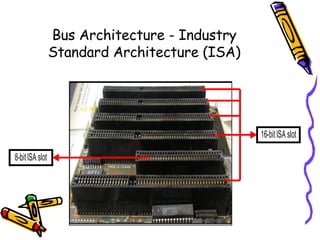
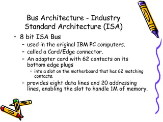
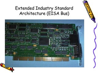
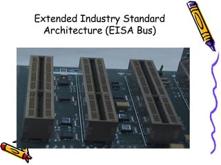
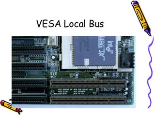
Chapter 6 Expansion Buses
What is a bus? connects the parts of the CPU to each other.  link the CPU to various other components on the system board.  a pathway for bits representing data and instructions.  The number of bits that can travel simultaneously down a bus is known as the bus width.
Categories of buses System Buses   connects the CPU to memory on the system board. Expansion Buses   connects the CPU to slots on the system board.
 
Processor bus the communication pathway between the CPU and immediate support chips.  used to transfer data  between the CPU and the main system bus between the CPU and an external memory cache.  the purpose:  to get information to and from the CPU at the fastest possible speed  tied to the external processor pin connections
Memory Bus used to transfer information between the CPU and main memory--the RAM in system.  As a dedicated chipset that is responsible for transferring information between the processor bus and the memory bus.  The information that travels over the memory bus  is transferred at a much slower rate than the information on the processor bus.  The size of the memory bus: controls the amount of memory that the CPU can address directly.
Address Bus a subset of the processor and memory buses.  used to indicate: what address in memory  what address on the system bus  indicates precisely  where the next bus transfer or  memory transfer will occur.
Bus Architecture - Industry Standard Architecture (ISA)
Bus Architecture - Industry Standard Architecture (ISA) 8 bit ISA Bus used in the original IBM PC computers.  called a Card/Edge connector.  An adapter card with 62 contacts on its bottom edge plugs  into a slot on the motherboard that has 62 matching contacts.  provides eight data lines and 20 addressing lines, enabling the slot to handle 1M of memory.
Bus Architecture - Industry Standard Architecture (ISA) 16 bit ISA Bus IBM introduced the 286 processor in 1984.  This processor had a 16-bit data bus, meant that  communications between the processor and the motherboard as well as memory would now be 16 bits wide  The introduction of the 286 chip posed a problem  IBM opted for the latter solution PC/AT was introduced with a set of expansion slots with 16-bit extension connectors.
Bus Architecture - Industry Standard Architecture (ISA) 32 bit ISA Bus After 32-bit CPUs became available,  it was some time before 32-bit bus standards became available.
Micro Channel Architecture (MCA) Bus
Micro Channel Architecture (MCA) Bus The introduction of 32-bit chips meant that the ISA bus could not handle the power of another new generation of CPUs.  IBM decided to build a new bus;  the result was the MCA bus.
Micro Channel Architecture (MCA) Bus MCA runs asynchronously with the main processor,  meaning that fewer possibilities exist for timing problems among adapter cards plugged into the bus. An MCA system has no jumpers and switches  Through implementing bus mastering, the MCA bus provides significant performance improvements over the older ISA buses.  Each device is given a priority code to ensure that order is preserved within the system.
Micro Channel Architecture (MCA) Bus 4 types of slots: 16-bit 16-bit with video extensions 16-bit with memory-matched extensions 32-bit
Extended Industry Standard Architecture (EISA Bus) was announced in September 1988 as a response to IBM's introduction of the MCA bus developed primarily by Compaq taking over future development of the PC bus away from IBM.  gave the design away to other leading manufacturers.  formed the EISA Committee, a non-profit organization designed specifically to control development of the EISA bus.
Extended Industry Standard Architecture (EISA Bus) provides 32-bit slots  enables manufacturers to design adapter cards that have many of the capabilities of MCA adapters,  supports adapter cards created for the older ISA standard.  permits greater system expansion with fewer adapter conflicts.
Extended Industry Standard Architecture (EISA Bus)
Extended Industry Standard Architecture (EISA Bus) adds 90 new connections (55 new signals)  without increasing the physical connector size of the 16-bit ISA bus.  The EISA adapter, however, has two rows of connectors.  The first row is the same kind used in 16-bit ISA cards;  the other, thinner row extends from the 16-bit connectors.
VESA Local Bus
VESA (Video Electronic Standards Associaion) Local Bus the most popular local bus design from its debut in August 1992 through 1994.  It was created by the VESA committee, a non-profit organization founded by NEC  to further develop video display and bus standards.  offers direct access to system memory at the speed of the processor itself.  can move data 32 bits at a time,  enabling data to flow between the CPU and a compatible video subsystem or hard drive  at the full 32-bit data width of the 486 chip.
VESA (Video Electronic Standards Associaion) Local Bus – Limitations: Dependence on a 486 CPU .  tied to the 486 processor bus.  This bus is quite different from that used by Pentium processors (and probably from those that will be used by future CPUs).  Speed limitations .  provides for speeds of up to 66MHz on the bus In practice, running the VL-Bus at speeds over 33MHz causes many problems,  Electrical limitations .  has very tight timing rules designed for limited loading on the bus Card limitations .  the number of VL-Bus cards is limited.
Peripheral Component Interconnect (PCI) Bus
The PCI bus specification, released by Intel in June 1992 and updated in April 1993,  redesigned the traditional PC bus by inserting another bus between the CPU and the native I/O bus by means of bridges. called a mezzanine bus  adds another layer to the traditional bus configuration. uses the system bus to increase the bus clock speed Peripheral Component Interconnect (PCI) Bus
can operate concurrently with the processor bus The CPU can be processing data in an external cache  while the PCI bus is busy transferring information between other parts of the system Peripheral Component Interconnect (PCI) Bus
System Resources the communications channels, addresses, and other signals  used by hardware devices  to communicate on the bus.  include the following:  Memory addresses IRQ (Interrupt ReQuest) channels DMA (Direct Memory Access) channels I/O Port addresses
System Resources -  IRQ (Interrupt ReQuest) channels used by various hardware devices to signal the motherboard that a request must be fulfilled.  represented by wires on the motherboard and in the slot connectors.  When a particular interrupt is invoked,  a special routine takes over the system,  which first saves all the CPU register contents in a stack and  then directs the system to the interrupt vector table.  contains a list of memory addresses that correspond to the interrupt channels.  Depending on which interrupt was invoked, the program corresponding to that channel is run.
System Resources -  IRQ (Interrupt ReQuest) channels The pointers in the vector table point to the address of whatever software driver is used to service the card that generated the interrupt.  For a network card, for example, the vector may point to the address of the network drivers that have been loaded to operate the card;  for a hard disk controller, the vector may point to the BIOS code that operates the controller. After the particular software routine finishes performing whatever function the card needed, the interrupt-control software  returns the stack contents to the CPU registers, and the system then resumes whatever it was doing before the interrupt occurred. Each time that a serial port presents a byte to your system, an interrupt is generated to ensure that the system reads that byte before another comes in.  Hardware interrupts are generally prioritized by their numbers; with some exceptions, the highest-priority interrupts have the lowest numbers. Higher-priority interrupts take precedence over lower-priority interrupts by interrupting them. As a result, several interrupts can occur in your system concurrently, each interrupt nesting within another.

Chapter 6: Expansion Buses

  • 1.
  • 2.
    What is abus? connects the parts of the CPU to each other. link the CPU to various other components on the system board. a pathway for bits representing data and instructions. The number of bits that can travel simultaneously down a bus is known as the bus width.
  • 3.
    Categories of busesSystem Buses connects the CPU to memory on the system board. Expansion Buses connects the CPU to slots on the system board.
  • 4.
  • 5.
    Processor bus thecommunication pathway between the CPU and immediate support chips. used to transfer data between the CPU and the main system bus between the CPU and an external memory cache. the purpose: to get information to and from the CPU at the fastest possible speed tied to the external processor pin connections
  • 6.
    Memory Bus usedto transfer information between the CPU and main memory--the RAM in system. As a dedicated chipset that is responsible for transferring information between the processor bus and the memory bus. The information that travels over the memory bus is transferred at a much slower rate than the information on the processor bus. The size of the memory bus: controls the amount of memory that the CPU can address directly.
  • 7.
    Address Bus asubset of the processor and memory buses. used to indicate: what address in memory what address on the system bus indicates precisely where the next bus transfer or memory transfer will occur.
  • 8.
    Bus Architecture -Industry Standard Architecture (ISA)
  • 9.
    Bus Architecture -Industry Standard Architecture (ISA) 8 bit ISA Bus used in the original IBM PC computers. called a Card/Edge connector. An adapter card with 62 contacts on its bottom edge plugs into a slot on the motherboard that has 62 matching contacts. provides eight data lines and 20 addressing lines, enabling the slot to handle 1M of memory.
  • 10.
    Bus Architecture -Industry Standard Architecture (ISA) 16 bit ISA Bus IBM introduced the 286 processor in 1984. This processor had a 16-bit data bus, meant that communications between the processor and the motherboard as well as memory would now be 16 bits wide The introduction of the 286 chip posed a problem IBM opted for the latter solution PC/AT was introduced with a set of expansion slots with 16-bit extension connectors.
  • 11.
    Bus Architecture -Industry Standard Architecture (ISA) 32 bit ISA Bus After 32-bit CPUs became available, it was some time before 32-bit bus standards became available.
  • 12.
  • 13.
    Micro Channel Architecture(MCA) Bus The introduction of 32-bit chips meant that the ISA bus could not handle the power of another new generation of CPUs. IBM decided to build a new bus; the result was the MCA bus.
  • 14.
    Micro Channel Architecture(MCA) Bus MCA runs asynchronously with the main processor, meaning that fewer possibilities exist for timing problems among adapter cards plugged into the bus. An MCA system has no jumpers and switches Through implementing bus mastering, the MCA bus provides significant performance improvements over the older ISA buses. Each device is given a priority code to ensure that order is preserved within the system.
  • 15.
    Micro Channel Architecture(MCA) Bus 4 types of slots: 16-bit 16-bit with video extensions 16-bit with memory-matched extensions 32-bit
  • 16.
    Extended Industry StandardArchitecture (EISA Bus) was announced in September 1988 as a response to IBM's introduction of the MCA bus developed primarily by Compaq taking over future development of the PC bus away from IBM. gave the design away to other leading manufacturers. formed the EISA Committee, a non-profit organization designed specifically to control development of the EISA bus.
  • 17.
    Extended Industry StandardArchitecture (EISA Bus) provides 32-bit slots enables manufacturers to design adapter cards that have many of the capabilities of MCA adapters, supports adapter cards created for the older ISA standard. permits greater system expansion with fewer adapter conflicts.
  • 18.
    Extended Industry StandardArchitecture (EISA Bus)
  • 19.
    Extended Industry StandardArchitecture (EISA Bus)
  • 20.
    Extended Industry StandardArchitecture (EISA Bus) adds 90 new connections (55 new signals) without increasing the physical connector size of the 16-bit ISA bus. The EISA adapter, however, has two rows of connectors. The first row is the same kind used in 16-bit ISA cards; the other, thinner row extends from the 16-bit connectors.
  • 21.
  • 22.
    VESA (Video ElectronicStandards Associaion) Local Bus the most popular local bus design from its debut in August 1992 through 1994. It was created by the VESA committee, a non-profit organization founded by NEC to further develop video display and bus standards. offers direct access to system memory at the speed of the processor itself. can move data 32 bits at a time, enabling data to flow between the CPU and a compatible video subsystem or hard drive at the full 32-bit data width of the 486 chip.
  • 23.
    VESA (Video ElectronicStandards Associaion) Local Bus – Limitations: Dependence on a 486 CPU . tied to the 486 processor bus. This bus is quite different from that used by Pentium processors (and probably from those that will be used by future CPUs). Speed limitations . provides for speeds of up to 66MHz on the bus In practice, running the VL-Bus at speeds over 33MHz causes many problems, Electrical limitations . has very tight timing rules designed for limited loading on the bus Card limitations . the number of VL-Bus cards is limited.
  • 24.
  • 25.
    The PCI busspecification, released by Intel in June 1992 and updated in April 1993, redesigned the traditional PC bus by inserting another bus between the CPU and the native I/O bus by means of bridges. called a mezzanine bus adds another layer to the traditional bus configuration. uses the system bus to increase the bus clock speed Peripheral Component Interconnect (PCI) Bus
  • 26.
    can operate concurrentlywith the processor bus The CPU can be processing data in an external cache while the PCI bus is busy transferring information between other parts of the system Peripheral Component Interconnect (PCI) Bus
  • 27.
    System Resources thecommunications channels, addresses, and other signals used by hardware devices to communicate on the bus. include the following: Memory addresses IRQ (Interrupt ReQuest) channels DMA (Direct Memory Access) channels I/O Port addresses
  • 28.
    System Resources - IRQ (Interrupt ReQuest) channels used by various hardware devices to signal the motherboard that a request must be fulfilled. represented by wires on the motherboard and in the slot connectors. When a particular interrupt is invoked, a special routine takes over the system, which first saves all the CPU register contents in a stack and then directs the system to the interrupt vector table. contains a list of memory addresses that correspond to the interrupt channels. Depending on which interrupt was invoked, the program corresponding to that channel is run.
  • 29.
    System Resources - IRQ (Interrupt ReQuest) channels The pointers in the vector table point to the address of whatever software driver is used to service the card that generated the interrupt. For a network card, for example, the vector may point to the address of the network drivers that have been loaded to operate the card; for a hard disk controller, the vector may point to the BIOS code that operates the controller. After the particular software routine finishes performing whatever function the card needed, the interrupt-control software returns the stack contents to the CPU registers, and the system then resumes whatever it was doing before the interrupt occurred. Each time that a serial port presents a byte to your system, an interrupt is generated to ensure that the system reads that byte before another comes in. Hardware interrupts are generally prioritized by their numbers; with some exceptions, the highest-priority interrupts have the lowest numbers. Higher-priority interrupts take precedence over lower-priority interrupts by interrupting them. As a result, several interrupts can occur in your system concurrently, each interrupt nesting within another.