Downloaded 30 times
![(4) 'urure of country: hc,,, r lrxrrow qlrugc o[ tl']e tlrrcli sinc. it,is ilrt''lc
I. rrrorrutaitlorts coLllltl'y' rt ts lJvisnble Io ltlvc"r
'"tll)' ?r,i' is t]rc ttr.itr rcrtsott * ltv sJrttc
ii.'i;i.'ili;;,, u'''"..il: llil"'lHIi:i-:i:ll]i,,'J'."^ll,,i;;;,t,.. g..us.. as r):.1ow 35 ortr
inlporr.;ult rails tys' t:t t''l'l j;,,ii;i;,., ,t.o influ.n... r'c choicc of guugcs
rlnt. Morcovcr. [outldat ttltl cc
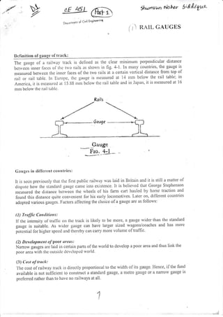
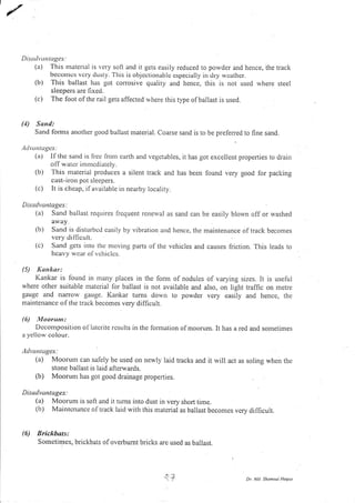
The <tifferent gauges cirn broadly be dividctl into four categorles:
(l) Broad gauge: Width l676 mm to 1524 rnm or 5'-6" to 5'-0"'
(2) Staudard gauge: Witlth I435 nrm and 1451 rnm or 4'-8 5" and 4'-91/8"'
(3) Merre gauge: Width
.l067
nrm' 1000 mm and 915 mm or 3'-6"' 3'-33/E" and 3'-0"'
(-l) Narrorv gaLrge: Width 762 r.nm and 610 mm or 2'-6" and 2'-0"'
TABLE 4.I
RAILWAY GAUGES IN VARIOUS COTNTRIES
Name of couutrtes
Bangladesh, India, Pakistan' Ceylon'
Brazil, Argentine
Spain, Portugal
lreland, South Australia
Russia, Finland
(1)Broutl guuge:
(a) 1676 mm
(b) I670 nint
(c) 1600 mnt
(d) 1524 mtrt
England, U.S A , Canada' TurkeY'
Persia, China. EgYPt' Australia
Europe (excePt Russia' SPain and
PortLrgal)
(2) Standartl guuge:
(a) 143 5 ntnr
(b) 145 I mnt
South Africa, Japan, Java' Australia'
New Zealand
Bangladesh, India, Fr ance' Switzerland'
Argeniine
(3) lvletre guuge:
(a) i 067 ntm
c) 91 5 tnm
India, Britain
lndia, South Afr-ica
(4) Nurrort' guugc:
(a) 762 mrr
(b) 610 mnt](https://image.slidesharecdn.com/ce-451part1railgauge-150110021601-conversion-gate01/85/Ce-451-part-1-rail-gauge-2-320.jpg)
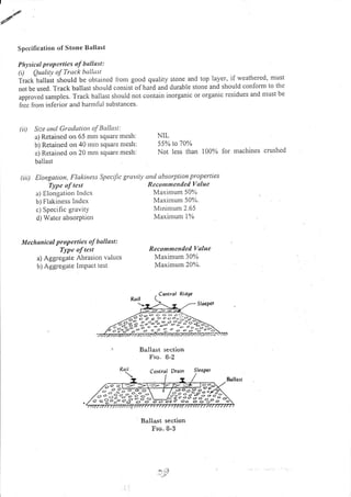
![Unifornrity in gauges:
It has bccn gcucrally agreed that a country should have a uuiforut gauge.'l'his I'act has Icd
to scrious thinking in thc coLuttrics lraving nrorc th:rn ot]c gaugc and attclllllts arc bcitlg nratlc to
pass an tct of Got,cntnrent in this connection. Various causes which have arisen due to non-
unilonrity ofgauges are as lollows:
( 1 ) Itrcottvutiencc to passcttgers
At the point rvhere therc is a change ofgauge, passengers are required to move from one
train to the other. This transler involves difficulties such as getting accommodation in the
nqv train, translerring luggage frorr one train to otlier, climbing staircases of overbridges,
ctc. Morcovcr'. tftc tirlilgs of thc t',vo trains arc to be correspoudingly adjusted. Sometit]lcs,
this ntay rcsult in ntissirrg the train and thell passengers lrave to pass the time orr tl.re
plarforms. Moreover, i:rsanitary condilions will be developed on the platfomrs due to their
conslant usc.
(2) Difficulties for se n irrg gootls
(a) The labour required lor loading and unloading the goods may go on strike and thus
completely dislocate the ntovement olessential goods required for various trades. The
problenr gets lurthcr complicated lor goods sent loose or in bulk such as coal, lime,
Iimcstonc, stonc chii)s, ctc. bccausc it is obscrvcd that at cvery transhipnlcnt point.
there arc certain groups of labourers rvhich are specialised in the handling of suclt
matcrials. Flence it becorres difficult to cmploy other labourers in an emergency, even
though there may be cousiderable unemployment in the area.
(b) lt is most likely that delicate goods may be damaged during the process of loading and
unloading.
(c) Thcfts or misplacenrent ofgoods nlay occur during the transhipping which may lead to
inconvenicnce to the pclsons concerned and long unnecessary corespondences are
thus unduly created.
(d) Large costly yards are to be provided at the junction o[ tl.re two gauges to store the
goods.
(c) Onc or nrorc cxlra chargcs rvill have to be paid by thc owncr of the goods rvhich will
result in the increase in cost of the product.
(3) Inefficient use of rolling stock:
It is quite clear that a wagon of metre gauge cannot be used on a broad gauge. Thus.
sometimes, this results in artificial shortage of wagons. Many wagons may be lying idle on
broad gauge line while there may be an acute shortage ofwagons on the metre gauge line.
Had there been a unifon.n gauge, sucl.t difficulty would never have arisen.
(4) War time dilficulty :
lfthe gauge is not unilolur tlrroughout the country,
by rail lronr one corncr of the country to the other
amount of time.
it becomes difficult to trarlsfer the arn.ty
comer of the country in a very limited
5) !)quipnrent at statiou:
A station where two gauges rneet, will have to be provided with duplicate facilities such as
platforms, sanitary arangements, sidings, clocks, ticket offices, etc. This will result in extra
J](https://image.slidesharecdn.com/ce-451part1railgauge-150110021601-conversion-gate01/85/Ce-451-part-1-rail-gauge-3-320.jpg)
![Uniformity in gauges:
It has bccn gcncrally agrccd that a country should have a unilbrnr gaugc. 'l'his liLct l.ras led
to scrious thinking irt tlrc countrics having nrolc tlran onc gaugc and tttctttPts arc bcitlg I.tladc [o
pass an act ofGovcntnrent in this connection. Various causes rvhich have arisen due to non-
unilornrity ofgauges are as lbllo*'s:
(l) Incontenicucc lo posscttgcrs
At the point rvfiere therc is a change of gauge, passengers are required to n]ove from one
train to the other. This transfcr involves difficulties such as getting accomn.rodalion in the
nes, train, transferring luggagc lrom one train to other, climbing staircases of overbridges,
ctc. Morcovcr. tlrc tintings of thc trvo lrains arc to bc corrcspondingly adjusted. Sonletittles,
thrs uray rcsult ir.r ntissing the train and thcn passengers llave to pass tlie tirle on the
platlonns. Morcover, insanitary condiliorls will be developed on the platlomrs due to their
col)stanI usc.
(2) Dilficultics for serrdittg goois
(a) The labour required lor loading and unloading the goods may go on strike and thus
completely dislocate the nlovenlent of essential goods required lor various trades. The
problem gets lurthcr conrplicated lor goods sent loose or in bulk such as coal, lime,
Iimcstope, stonc chips, ctc. bccausc it is obscrvcd 1ha1 at cvery transhiltrucnt poiltl.
there arc ccrtain groups ol labourers rvhich are specialised in the handling of such
matcrials. Flence it becoures difficult to enrploy other labourers in an emergency, even
though therc rnay L.:e cot.tsiderable unentployment in the area.
(b) It is most likely that delicate goods may be damaged during the process of loading and
unloading.
(c) Thefts or misplacenrent of goods may occur during the transhipping which may lead to
inconvenicnce to tlle pcrsons concemed and long unnecessary correspondences are
thus undu ly c reated.
(d) Large coslly yards are to be provided at the junction of the two gauges to store the
goods.
(c) Onc ol ntorc cxtra clrargcs will have to be paid by thc ownet'of the goods rvhicir rvill
result in the increase in cost of the product.
(3) Incfficient use of rolling stock:
It is quite clear that a wagon of metre gauge cannot be used on a broad gauge. Thus:
sometimes, this results in artificial shortage oiwagons. Many wagons may be lying idle on
broa<l gauge line while there may be an acute shortage ol wagons on the metre gauge line.
Had tl.rere been a unifon.u gauge, such difficulty would never have arisen.
(J) war time dilliculty :
If thc gauge is not Lrni fornr throughout the country, it becomes dilficult to trai]sfer the arnly
by rait from one comcr ol'the counl.ry to the otller corner of the country in a. very Iimited
aniount ol tinre.
5) llquipment at station:
A station where two gauges rneet, will have to be provided with duplicate facilities such as
platforms, sanitary arrangements, sidings, clocks, ticket ofhces, etc. This will result in extra
?t
{'](https://image.slidesharecdn.com/ce-451part1railgauge-150110021601-conversion-gate01/85/Ce-451-part-1-rail-gauge-4-320.jpg)

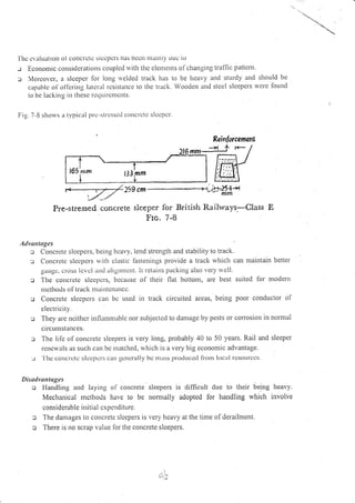
![Rails
Irunction of Rails
Rails are sintilar to steel girders. Thcse are placed end to end to provide continuous and level
surlacc for the trains to nrove. Thc finishcd or conrpleted track of a railway line is commonly
krrorvn as Peraunu I,Va.1,.
Rails pcrform the following functions:
l. The rails provide continuous and level surface for movement oftrains.
2. The rails provide a pathway which is smooth and has very less friction. The friction
be[veen steel rvhee] and stecl rail is about l/5th of the friction between the pneumatic tyre
aitd metalled road.
3. The rails scrve as a latcral guide for the running ofwheels.
'1. The rails bear the strcsses developed due to vertical-loads transmitted to it through axles
anLl rvhecls ol rolling stocli as rvcll as due to braking forces and tl'reflral stresses.
5. The rails carry out thc lunction oltransmitting the load to a iarge area of formation tluougl.r
slecpers and ballast.
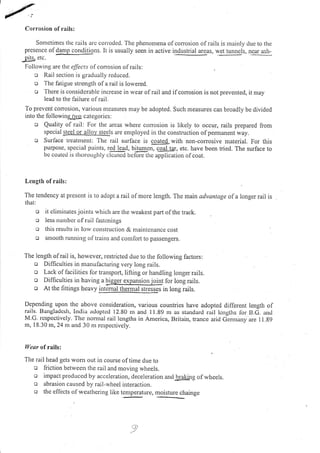
Types of rails
I . Double hcarlcd rails
2. BLrll lreadcd r:r i ls
3. FIat lootcd rails
originally, the rails used were double headed (D.H.) and made of "I" section or Dumb-bell
section (Fig. 5.1.) The idea *,as that when the head was vr'om out during the service, the rail
cotrld be invertcd and reused. Tl.re expcrience, horvevcr, ihowed that the bottom table of the rail
was dcntcd to such an cxtent in scrvice by long and continuous contact with the chairs that it
was nol possible to reuse it. This led to the development of Bull headed (B.H.) rail which had
almosl a sinrilar shape but with nrore metal in the head to allow for greater wear and tear (Fig.
5.2)' This rail scction had orte big dlawback that chairs were required for fixing it to the
slcepers.
A llat lboted rail, also callcd vigttolc rail (Fig.5.3), having a cross section ofinverted r- type
lvas, tltcrcforc, dcvclopccl wltich coLrkl bc fixcd dilcctly (o thc slccpcrs witlr thc lrclp of spikcs
ctc- Allothcl' advatttogc wilh tlrc flat-looted lail was that it was a morc ccononlical tlcsign
giving grcatcr strcrtgLh arl(l latcral stability to thc track as cornpared to a B.ll. rail lor a given
cross sectional area.
Adrn,,trgn, of flat looted rails:
(i) Chairs: No chairs are required in this fonn ofrails. The foot ofthe rail is directly spiked to
the sleepers. This fact nrakes theur economical.
(ii) Stllessr This fonn of rail is stiffer, both vcrtically and laterally than the bull headed rail
ofequal weight. Especially on curves, the lateral stiffness ofrails is vely impofiant.
(iii) Rinks: This lbrnr of rail is less liable to develop kinks and it maintains a more regular top
( o-a
r](https://image.slidesharecdn.com/ce-451part1railgauge-150110021601-conversion-gate01/85/Ce-451-part-1-rail-gauge-6-320.jpg)
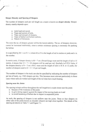
![W,;ight of rail and its relation to uxle load
A rail is dcfincd by its rvcight, c.g,,45 kg rail means that rhe weight of rail per rnetre lcng[h is
45 kg. Scvc'rai lactors arc to be considered belore deciding the rveight olrail and its sections,
the chief aniong tltem are as follorvs:
L hcav icst axle load
2. gauge of track
3. maximum pcnlrissiblc spced
4. type and spacing ofslecpers
5. depth ol ballast cushion
6. nalure of traffic.
Though the weight of the rail and its section depends upon various considerations yet the
heaviest axle load which tl.re rail has to carry plays, the most important role. It is lound and
vcrificd by cxperinlcnts that the axle loads on locomotives directly depend on the weight of
rails used in thc track.
Tirc lbllorving is thc thu:rib ru)e lor giving the rnaximum axle load with relation to rail section :
Maxintum axle load
For rril of 90 lb pel yard, rnax. axle load
For- r-ail of 52kg per n1, ntax. axle load
Requirements for an ideal rail section'
l. The rail should have most economical section consistent with strength, stiffitess and
d urab i tity.
2. 'l'hc ccrrtrc olgravity olrail section slrould prelerably be very near to 1he centre ofheight of
rail so that nraxinrurn tcnsilc and conrprcssivc stresses are equal.
'1. A rail prirnarily consists ol a head, web and foot and there should be an economical and
balanced distribution of utetal in its various components so that each of them can fulfil its
requirernents properly.
The requiremetrts as well as the niain considerations lor design ofideal rail section components
are given below:
(u1 IIeod:
The head olthe rail should have adequatc depth to allow for vgrtical wear. The rail head
should also be sulliciently wide so that not only wider runnirlg sufrdis available to
reduce lhe contact strcsscs betwcen the rain and whecl but the rail has the dcsired ]atcral
stiffness also,
(b.t Web:
The web should be su ffi c.lg1.lI1b@k so as to wirhstand tl.re stresses d.e to the loads
corning on it aft", oli6iil! fonio.rnal conosion.
(c) Foot:
The foot should be of sufficient thickness so as to withstand vertical and horizontal
lorces after allowing for loss due to corrosion. The foot should be wide enough so as to
be stable against over tuming. The design of foot should be such that it can spread the
load on a large arca of sleeper.
= 560 x sectional weight of rail in lbs/yard or kg/m
: 560 x 90 lbs = 22.5 tons
560 x 52 kg - 29.l2MT
'+](https://image.slidesharecdn.com/ce-451part1railgauge-150110021601-conversion-gate01/85/Ce-451-part-1-rail-gauge-8-320.jpg)
![Li'!<->,
Thcsefactorscauseconsidelablervearandtearotrverticalandlateralplanesoniheraillrcad.
Eventually, u'lrich results in loss of weight ofrail'
Types of wear on rails:
Dcpcnding upon its location, thc rvcar ol'rails can bc classified as lollows:
o Wear orr top of rail hcad (vcrtical wear)
l Wcar on cnds of thc rails (battering of rail cnds)
c Wear on sitlcs of rail head (lateral wcar)
Each type rvill norv bc described in briel
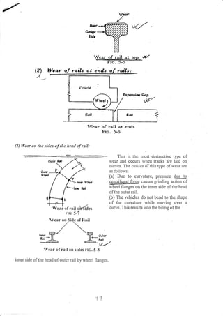
(t) lcur ott loP o,' hcutl of rails:
Therrretalfromtltctopofrailtlorvsandlomrsprojections'Theseareknownasbltlgasshown
rn fig. S-S. Follorvingare lhe c4trscs lor such type of wear ofrails:
(a) Rails are wonl out on top due to abrasioll olthe roiling wheels over them
(b) The heavy rvliecl loatls are conccntrated on very small areas This results into flow of
metal from toP.
(c) Impact of heal'y loads causcs top ofrail to wear'
(c])Wheelburirscausedbyslippingofthedrivingwheeloflocomotivesontherailsur.face
resulting in a dcpression oll the rail table'
(e) The grinding action of the sgd.pSrtjqes between the rails and wheels help wear of rail
on toP.
({) Conosion olmc(al olrails, especially"tl"giEu, will cause wear of head of rails'
ig) the metat of top o l1a!![g1s during starti])g whcn the wheels slip or rvhen
'brakes
are
lpplicd to tltc tlor ittg lrritts'
(2) lVctr al tht tnls of rtils:
This rvear of rails takes place at the ends ofrails and is found to be very much greater than the
*"", u, ,op of rails. At ihe expansion gap, the wheels ofthe vehicle have to take a jump and
Juring ttrii 1ump, they impart i uto* ,J ti.,. ends of the rarts as shown in hg. 5-6. This blow is
,f*
"i^i" "uus"
of *ror of rails at ends. Due to successive blows, the ends of the rails are
battcrcd and various othcr cflccts are sccn whicl.r further increasc this type of wcar' These
effacts ate as follows:
(a) Fish-bolts and fisll-piatcs bdcorne loosc
(b) The colltact surlaces betwecn rails and sleepers are wom ou['
i.j it""p.r, at expansionjoints are depressed due to settlement ofballast at these points.](https://image.slidesharecdn.com/ce-451part1railgauge-150110021601-conversion-gate01/85/Ce-451-part-1-rail-gauge-11-320.jpg)
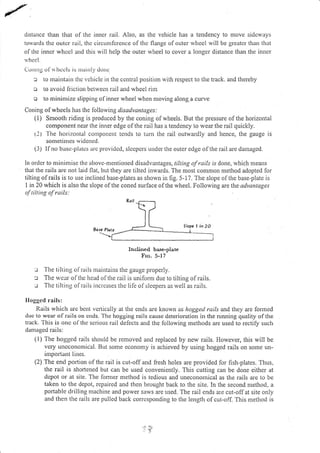
![(c) The rvear on inner side olhead ofinner rail is mainly due to lhe slipping actlg]lgf w_hgei on
curves. lt is clear liom fig. 5-7 that the outer wheel has to cover a longer distance than the inner
u'heel as pg is grcater tiran rr. But due to rigid connections betwcen two wheels, thcy cover the
same distancc and hcnce, the inner whcel slips ovcr the inner rail, resulting in the wcar of inner
side oIhcrd of irrncr rail. [:ig. 5-ll sJrorvs thc rvear olrail on sidcs.
Nlcthods adoptcd to reduct rveur of rails:
In addition to coning ofrvhcels and super-elevation, various nrethods, as nrentioned below, are
uscd lor the purpose of rcducing rvear of rails:
o Use olspecial alloy steel
c Use of heavier rails
o Good nraintenancc of track
o Reduction of expansion gap
o I{eductron ol nunrbcr ofjoints by wclding
o Exchange ofinner and outer rails on curves
o lntroducing parallcl clrcck rails (usually wont oul. rails are used as check rail)
c Lubrication olgaugc lacc olouter rail in case olcurves.
-.
Coning of rvheels:
The flanges ofrvhecls al.c ncver made flat. But they are in shape of a cone with a slope ofabout
I in 20. As the ivhecls are set on the axle, there is some chance for lateral movement belween
the flanges of the wheels and the rails. Hence, without coning, the flanges rvould cause a slight
but sudden shock to the sides of the rails-
Behaviour ofconed rvlrcels on straight and level track is shown in Fig:5-15. In this case, tl.re
llaugcs ol rvhccls have eclual circumlcrence. But the situation is different when the wheels
move along a curve as shown in fig. 5-16. In this case, the outer rail has to cover a greater
flongc Coned ! in 2O
Bchaviour of concd whecls on.lcvel track
Fro.5-15
l:20
l: f o
lrrret Roll Oulcr
Bchaviour of coned wheels on
Fro.5-16
Roil
curveS](https://image.slidesharecdn.com/ce-451part1railgauge-150110021601-conversion-gate01/85/Ce-451-part-1-rail-gauge-13-320.jpg)
![uscd in U.S.A. aud was provcd to be quite successful
(l) Fioggctl rails can bc inrproved by rvelding the rvom ends of the rails'
(1)Hoggedrailscallalsobeinlprovedbysorrresirrrplcclcvicesuclrasadelnggedntuckinc.'
It c-o-nsists of a bottie jack, , lcngtt] of old rail and two sets of clamps. This machine is
uscd ,,vitlt sttcccss in India.
Ilucklittg;
Sonrctinres, lorrlatior.r ol buckles takcs place which nleans that the track has gone out of its
original poiition. This happens on.,,ru.i when expansion ofrails is prevented. The preve.tion
oI erpltision Ittay bc due- to ottc ol'the Ibllowing ,]vo causes:
(l) insulficietlt cx1;attsion gap. antl
(2) excessive tiglitncss of the joint.
Buckles in tracks are serious ancl sonletimes, they are responsible for the derailments of the
trains. Hcncc, propcr ci)rc shoulcl be takelt to avoid buckles. Precautions to be taken are as
follorvs:
i. Expar:sion ga1; shoulcl be sulficicnt.
2. The fish-bolts shor.rld not bc tightcned up to such an extent as to prevenl expansion or
contracl.iott ol' rli ls.
j. The corltact surlaccs bctrveen thc fish-plates and rails should be periodiially lubricated.
hL](https://image.slidesharecdn.com/ce-451part1railgauge-150110021601-conversion-gate01/85/Ce-451-part-1-rail-gauge-15-320.jpg)

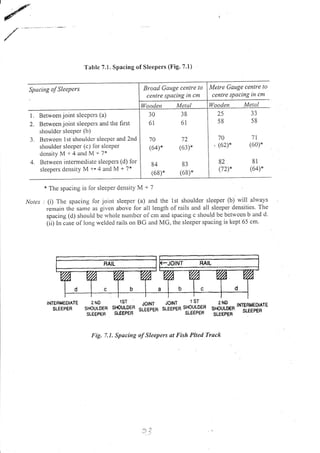
![t4//
Depctrding Lrpon the rnateriul transverse/cross sleepers may is classified as
-.r 'oodcn slccpcls
-.i Stccl s lccpcrs
r Cast iron s lccpers
J Concrctc slccpcrs.
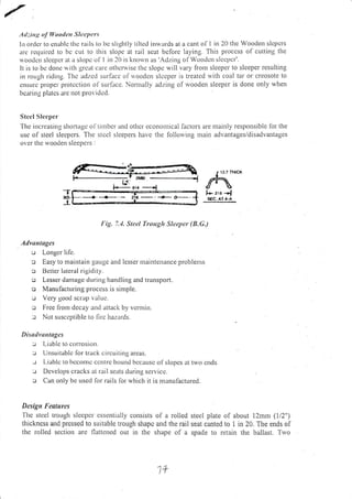
'oodcn Sleepers
Woodcn sleel;er is thc tttost idcal typc ofslecpcr and it is being used universally ahlost evel'
sittce tltc invctt(iott of Ilil*.tr,. Its utility hus not tlccrcascd witlr thc passagc of tinrc. Only thc
possiblc sltorl:rgc ol's,ooti ir fittttrc hus lcrl ltr llrc llrirrltirrg ofslccpcrs ol'othcr ntatcrials.
Ihc rvoodcn slcepcr Iras tlte It-rllorvitrg lrrirrn advantagcs arrti rlrsadvurrtrt:es .
Adyflrtl ges
o Cheap arrtl casy Lo ntanLrlacturc.
:: Absorbs shocks lnd Ius gor good ca1:acity to dantpetl the vibrations
o Thercby retarns packing rvell.
c Easy harrclling witllout diintagc.
o Suitahlc for track cilcuited sections.
: Suitablc lbr aleas har,ing yielding forntations.
u Alignnrent can bc easily corrected.
:: Morc suitable lol rnoclr: rn tncthods of nraintcnancc.
Lr Can bc uso(l u,itir or rvithout stone ballast.
e Cirn be uscd on blitlgcs and ash pits also.
Disulvuntagas
i.: l,csscr iil'c iluc to n,car, dccay and attack by vennin.
u Liablc to mcchanical wcar rvitlr bcalcr packing.
o Difficulty to nraintain gauge.
o Susceptible to llrc hazards.
tr Scrap value is negligible.
Sr.c.'The size of'sleepers will depend
Standard sizes ol- titnber slccpers used
: I;or [].C., 274 cl"r x 254 rnnt x
c For M.G., 183 cnr x 203 nrnr x
:.t Iror N.G., I 52 cnt x 178 rnrr x
upon the load coming and the quality of wood.
are as follo*,s:
127 nrnr.
I l4 rnm.
I I 4 nrnr.
,jL](https://image.slidesharecdn.com/ce-451part1railgauge-150110021601-conversion-gate01/85/Ce-451-part-1-rail-gauge-17-320.jpg)
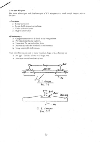
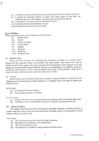
![lultcrnativc typcs of slccltcls htrvc bccn designcd lbr each raii section as. per dctails givcll
hclorr:
(l) ln otlc t),pc, thc lLrgs or jarvs arc ltlcsscd out ol'thc platc itscll- to irccollll)]ollatc tllc
lbot ol rlrc rail a:rd thc kcy (Fig.7.5). Thele are a lot ol maitttenance problenls with
rlrese llrc'sscd up Iugs its thcy git,c way duc to the utoventeut of thc keys as rvell as due
to the vihrations ancl itrtpact of tlre nloving 1oads.
(2) 11 ordcr to obviatc this dc{cct. auolhcr dcsign ol slcspcl's has bcctl adopted. In this
typc, to hoies ar.c punchcd in the plarc on cither sidc ol the plate to acconlnlodate
specially dcsigned 'Loosc jarvs' (Fig 7.6). Thc rails are l.reld rvith the help of trvo
stantlartl ke;'s tlrivcrr cithcr i:r thc lttcsscti Lt1> lttgs or in the loose-jarvs.
Fig.7.5.Sslcepcr with pressetl- up lugs
'l'he adjustntent of thc gauge to tltc cxteltt oli 3 tunr (1/8") is dole by proper driving of the
keys. In the dolble linc section, the keys are driven in the direction of traffic. The weight of
standard B.G. tlough slccpcr is 81 kg and that ol M G. sleeper is 35 kg approximately. The
stcel Irou,lh slecpcr has iln avcrage lif-e olaboLrt 50 years. It is an acceptable type of sleeper
lbr usc witS long rvcllcd rails bccaLrse of its latcral stability and its adaptability for use u'ith
clastic lastcn ings.
KEY Ki:Y
l;ig. 7.6 Sleqtet' x,itlt loosc.iatt,s irrscrted itr ltoles
^rJ!
."i, l,
Fig, 7-7 Steel sleeper *,ith bolts
PEESSED
LOSEJAW
$$mTEo W](https://image.slidesharecdn.com/ce-451part1railgauge-150110021601-conversion-gate01/85/Ce-451-part-1-rail-gauge-19-320.jpg)
![Cornparison ol cltaractcristics of dilTcrcnt typcs of slecpcrs
Cltu ructcrstics ['l'oolut Stee I slecpers L'.1. s lcapcrs Concrcte slacpcrs
l. Scrvicq lil'c
2. Wcighr lor B.C.
3. Ilandlrng
-l l'r,pc o1'
nrailltenancc
5. Cost of
ntailttertance
6. Cauee ad justrncnt
7. Track circLriting
E. Danrage by whitc
ants and corrosion
9. S uitability lor
lastening
10. Suitablility to
track
I l. Track clast ic ity
I 2. Creep
13. Scrap valuc
l2 to l51,rs.
83 kg
M an Lral;
No darl;rgc
rvlrilc lt anciling
NIattLral tlr
nr cchan izcd
H i_qh
-=GDil'ficLrTh/
Bcsl
Can bc dantaged
by white ants
Suitablc lor
CF&EF
Suitable lor all
foulcs*
Good
Crcep is
cxcess ive
Low scrap valuc
3U to -10 yrs.
179 kr
lu,'nurt ;
lNo danra-ge
lrr h r lc hrnd linu
I
lMrrr,r.il ,,,.
lnrcchanized
I
Mediunr
t-- ._--
lEasv
I
lDiificLrlt;
I lnsLr Illt ins nads
lrr"
n"..rlrrv
No darlage but
corToston rs
possible
Suitable for
CF&EF
Suitable lor all
routes
Good
Less creep
Highcr scrap
value than
wooden sleeper
140 to 50 vrs.
lr, *n
1r,,,1,,,,
lLiablc to break
bv ro Lt ult hrnd Iin l
1r"","].,,,
I
Medium
!-.
lEasy
I
t_--
lDl ttl c Ll lt.
llnsuletinB
pads are
nec csse ty
Canoe dantaged by
coIroston
Suitable for
only CF
Not suitable 1br
hrgh speed routes
High scrap vahre
Good
Less creep
50 to 60 yrs.
267 kg
Mcchanized;
Gets dauraged
by rough hand lrng
Mechanized only
Low
No adiustmer.rt
possib le
Easy
No damage by
white ants or '
corrosion
Suitable for
only EF
Suitable for high
speed routes.
Best
Creep is
minimum
No scrap value
t Also suitablc lbr track circuititrg, lcvcl crossing and poinrs & Crossings... Large nunrber ol.anchors required to prevent &cessive crrep.
CF stands lbl convcntional lastcning & EF stands for elastic fastening.
{/
I
{](https://image.slidesharecdn.com/ce-451part1railgauge-150110021601-conversion-gate01/85/Ce-451-part-1-rail-gauge-23-320.jpg)

![,d
Adva lugcs:
(a) Brickbats arc uschrl in places where suitable rnaterials lor ballast are not available.
(b) Brickbats havc gr.rt lairly good drainagc propcrtics.
Dis(dru tuges:
(a) Brickbats turn dowt'l into powder lorm very easily and
(b) it becoues very difficult to maintain the track in
the track becomes dustY.
good condition where this
ruraterial is used as ballast.
(c) Rails are olten corrugated ou the track laid witir ballast ofbrickbats.
(8) Selected earth:
For sidings and also for newly laid railway tracks, selected earth is sometimes used as
ballast.
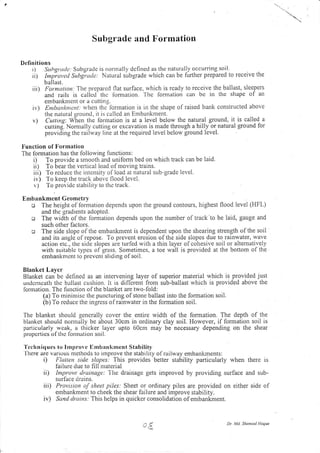
Minimum depth of Ballast Cushion
The depth ol the ballast is dcflncd as the distance between the bottont of sleeper and top of
subgrade. This depth of ballast is very important in deternlining the carrying capacity of the
track.
The loacl conting on the sleeper is transferred through the medium ofballast to the formation.
The pressure distribution of the ballast section depends ripon size and shape of ballast and
dcgree ol consolid:rtior.r etc. Through the lines of equal pressure are in the shape of bulb, yet
foi simplicity, the dispersion of load can be roughly assumed at 45 degree to the vertical. In
order to cnsurc that thc load is translcrrcd cvcnly otr thc lon.ttatiott, the dcpth of ballast should
be cnouglr so that dispcrsion lines do not overlap each othcr.
FIG. A.I MINIMUM DEPTH OF BALIAST CUSHION
It can be proved by a simple geometry that for even distribution of load on the formation, the
depth ofballast is given by the fonnula.
Sleeper spacing: Width ofthe sleeper + 2 x depth ofballast.
Assuming that the track is laid with woodon sleepers to N + 6 slecper densrly, thc slccpcr
spacing is ],5" and width of sieeper is 10", the minimum depth of ballast fi'om the above
consideratioir comes to 7 112'. A rninimum cusliion of 15 to 20 cm. (6" to E") of ballast below
the sleeper bcd is, therefore, nomrally prescribed.
Dt. M.l. Sh.,nsul Lloque
J'1'. '
Y"](https://image.slidesharecdn.com/ce-451part1railgauge-150110021601-conversion-gate01/85/Ce-451-part-1-rail-gauge-28-320.jpg)
![{
) Itiver!(tl fittcr. A blarlkct of adequalc thickness or illvetlctl filtcr is providcd
)
;:ii"";;; 11.,iirt, ,,,.1-*"rr for:'ration to improve stahilitv
,.'i) Ct'rrcrrt s,rotttittg:irrlt]lLUii'i" I*p't"ini tr'" stahiIitv"of the bank'
lii) !;;;;;;,/i;;.
:irh"'
';;;J
pit'i' (ro"pl"t tlre-soii and pr6vide mechanical support 10
,,,,.,
tlll*,),1.0,,i-
tt of soir: Che,.rical a,d mechanical srabilization l.ras the potential to
inrurove stability o l' thc entbattknrent'
irt Giorett ile,".l,,,,q,l"r li1,iJr.,.ipt 1,,,'i*p.'ing dri'inage and provide resistance to
thc soil bed and thcreby inrprove the slablllly
t"il':.:i:lif;::'lii
3,l,,",,ilji.tjl'li.>oir has rcccnrry been gg.,qlop"a in mrnv
:::,il,l::.:,f
,h"
rt.rtrt bv usc ol.Cl-OTE I f LLBI iiiir',*'* 'rri.i;,ri "
U^i.ullv'rttrdc trp ol polyurcr. irrrd lrrs
uniquc properry ol.ullo$ing r rr?"r, rt"i"ro fasr itriougtr but noi iire soil fines. ceotextiles r.r ork
not only as sepalalors ono
"'it"
n" il'L a'uin thE water and provide reinforcemellt to the
soil bed.
Allyerofgcotextilclsnorrrtallyl;rideitherdirectlybelowrhehallast.sometimesitrslaidas
sandu,iched betrvceu rry",. oi'r'",,i'lo iii"i u.ri.r, does nor reir airectty on the ceotextile and
il;1";td;;." of te ar and purlcture gets redr-rced
BALLAST
t-t<;- 9.7 FUNCTIoNs oF aEot'Ex'|-ILES
r!,IOISTUHE
rta. 9.E LIvNA l)l Gtol LrnLEs
MOISTURE
TBAN9POBTED
ALONG PIANE
OF FABAIC &
THROUGH
AALLAST
SOIL FINES
RETAINEO
SELOW FABRIC](https://image.slidesharecdn.com/ce-451part1railgauge-150110021601-conversion-gate01/85/Ce-451-part-1-rail-gauge-31-320.jpg)

1) The gauge of a railway track is defined as the clear minimum perpendicular distance between the inner faces of the two rails. Gauges are measured at different heights below the rail table depending on the country. 2) Factors affecting the choice of gauge include traffic conditions, development of poor areas, cost of track construction, and the nature of the country. Uniformity in gauges is generally agreed to be beneficial but different countries initially adopted various gauges. 3) Non-uniformity of gauges within a country can cause inconvenience to passengers and difficulties in transporting goods between lines of different gauges. It also results in inefficient use of rolling stock and hinders future conversion of track gauges.


![Rail Gauges and Rail standards [Useful for Civil Engineering Students IECT SPPU]](https://cdn.slidesharecdn.com/ss_thumbnails/railstd-171229080239-thumbnail.jpg?width=640&height=640&fit=bounds)


