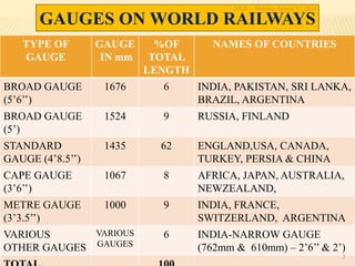
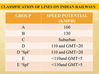
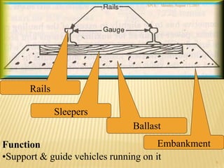
Civil Engineering
S S KALRA
Sr. Prof. (Civil Engg), NAIR
Monday, August 17, 2015SPCE
1
GAUGES ON WORLD RAILWAYS
TYPE OF
GAUGE
GAUGE
IN mm
%OF
TOTAL
LENGTH
NAMES OF COUNTRIES
BROAD GAUGE
(5’6’’)
1676 6 INDIA, PAKISTAN, SRI LANKA,
BRAZIL, ARGENTINA
BROAD GAUGE
(5’)
1524 9 RUSSIA, FINLAND
STANDARD
GAUGE (4’8.5’’)
1435 62 ENGLAND,USA, CANADA,
TURKEY, PERSIA & CHINA
CAPE GAUGE
(3’6’’)
1067 8 AFRICA, JAPAN, AUSTRALIA,
NEWZEALAND,
METRE GAUGE
(3’3.5’’)
1000 9 INDIA, FRANCE,
SWITZERLAND, ARGENTINA
VARIOUS
OTHER GAUGES
VARIOUS
GAUGES
6 INDIA-NARROW GAUGE
(762mm & 610mm) – 2’6’’ & 2’)
Monday, August 17, 2015SPCE
2
Monday, August 17, 2015SPCE
3
CLASSIFICATION OF LINES ON INDIAN RAILWAYS
GROUP SPEED POTENTIAL
(KMPH)
A 160
B 130
C Suburban
D 110 and GMT<20
D ‘Spl’ 110 and GMT>20
E <110and GMT<5
E ‘Spl’ <110and GMT>5
MAJOR AREAS OF RESPONSIBILITY
1. PERMANENT WAY
2. WORKS
3. BRIDGES
Monday, August 17, 2015SPCE
4
PRINCIPAL FEATURES OF PERMANENT-WAY
Monday, August 17, 2015SPCE
5
Function
•Support & guide vehicles running on it
Sleepers
Ballast
Embankment
Rails
Monday, August 17, 2015SPCE
6
Rails are members of the track laid in two parallel lines
to provide continuous surface for the movement of
Trains.
Function of rails
 Provide a continuous and level surface
 Provide a pathway which is smooth and offers
less friction
 Lateral guide for the wheels
 Bear changes due to vertical loads etc.
 Transfers load to formation through sleepers on
wider area.
RAILS
Monday, August 17, 2015SPCE
7
 BG 60 KG, 52 KG, 90R
 MG 90R, 75 R, 60R
 NG 50 R
 Rail is Designated by Weight Per Unit Length (Kg/m or Lb/yd)
 KG- Means Kg/m (Indian Railway Standards)
 R- Revised British Standards ( Lb/yd)
IRS 52 kg 880 SAIL X10 OB
IRS 52 kg 710 TISCO V 1991 OB
Monday, August 17, 2015SPCE
8
Standard Rail section
Monday, August 17, 2015SPCE
9
SERVICE LIFE OF RAILS
RAIL
SECTION
TOTAL GMT
CARRIED, FOR
72 UTS (MM) RAILS
TOTAL GMT
CARRIED
FOR 90UTS RAILS
60 KG 550 800
52 KG 350 525
90 R 250 375
Monday, August 17, 2015SPCE
10
Functions:
To Maintain Gauge distance
To distributes load over a greater area
To provide resilient bed
To maintain track to level & line
SLEEPERS
Monday, August 17, 2015SPCE
11
 Wooden -0.3%
 Steel- 1.5%
 Cast Iron – 4.0%
 Pre Stressed Concrete- 94.2%
 Fibre Reinforced Plastic
Different Types of Sleepers
Type Wooden Steel CI PSC
Service life (Yrs) 12-15 40-50 40-50 50-60
Weight(Kg) 33 79 87 267
Monday, August 17, 2015SPCE
12
Concrete sleepers (PSC)
Advantages
(a) Being heavy, tend more strength and stability to the
track and specially suited to LWR
(b) With elastic fastening, all along the track to maintain
better gauge, cross level & alignment
(c) Being flat bottom, suited for mechanical maintenance
(d) Can be used in track circuited areas
Disadvantages
(a) Handling and laying difficult
(b) Damage at time of derailment
(c) No scrap value
(d) Not suitable for beater packing
Monday, August 17, 2015SPCE
13
Elastic fastenings
Requirement of an elastic fastening
1. It should hold the gauge firmly in place
2. It should have an adequate toe load
3. It should provide sufficient elasticity to absorb the
vibratory shocks
4. It should offer adequate lateral resistance.
 Grooved Rubber Pads
 Liners
 Elastic rail clips MK III
Monday, August 17, 2015SPCE
14
Monday, August 17, 2015SPCE
15
Different Types of Concrete Sleepers
Normal line sleepers
Points & Crossings
Guard rails
Switch Expansion Joints
Check rail on curves
Level crossings
Dual Gauge
BALLAST
 Sleeper rests on a bed of stones called ‘Ballast’
Functions:
 Distributes load over a greater area to ‘formation’
 Provides elastic & resilient bed
 Helps to maintain track to level & line
 Helps in drainage.
 Longitudinal & lateral stability to track
Monday, August 17, 2015SPCE
16
REQUIREMENTS OF GOOD BALLAST
 Tough and wear resistant
 Hard to resist abrasion and attrition
 Non-porous and non-absorbent of water
 Durable and should not get pulverised due
to weather
 Cubicle having sharp edges
 Cheap and economical
 Size between 20mm – 65mm
Monday, August 17, 2015SPCE
17
FLAWS IN RAILS/WELDS
 Inherent defects
 Defects due to fault in rolling stock
 Excessive corrosion
 Badly maintained joints
 Defects in weld joints
 Improper maintenance of track
Monday, August 17, 2015SPCE
18
Monday, August 17, 2015SPCE
19
Monday, August 17, 2015SPCE
20
ULTRA SONIC FLAW DETECTION OF RAILS
BY TROLLY 2-3 KM/DAY
BY SPURT CAR 100-200 KM/DAY
SPURT- SELF PROPELLED ULTRASONIC
RAIL TESTING CAR.
Monday, August 17, 2015SPCE
21
SYSTEMS OF TRACK MAINTENANCE
 Conventional system
 From one end - periodic
 Directed Track Maintenance (DTM)
 Need based - as per requirement
8/17/2015SPCE
22
METHODS OF PACKING OF TRACK
 Manual (beater) Packing
 Systematic Through Packing
 Systematic Overhauling
 Picking up of slacks
 Machine Packing
8/17/2015SPCE
23
MACHINE MAINTENANCE
Necessitated due to
 Heavier track, difficult to maintain manually.
 Damage to Concrete Sleepers due to beater packing
For
 Uniform Packing
 Longer retentivity
8/17/2015SPCE
24
8/17/2015SPCE
25
TRACK GEOMETRY
MAIN PARAMETERS
 Gauge
 Alignment
 Unevenness- deviation in vertical plane
 Cross Level/Twist –out of planeness of one of
the four wheels
METHODS OF MEASUREMENT OF
TRACK GEOMETRY.
Manual
Track Recording Devices
 Microprocessor Based Track Recording Car
8/17/2015SPCE
26
8/17/2015SPCE
27
WORKS ON TRACK
 Works of routine maintenance
 Works of short duration
 Works of long duration
PROTECTION OF LINE IN CASE OF WORKS OF
SHORT DURATION AT STOP DEAD RESTRICTION
8/17/2015SPCE
28
DOUBLE LINE SECTION
PROTECTION OF LINE IN CASE OF WORKS OF
SHORT DURATION AT REDUCED SPEED
SAME AS IN CASE OF STOP DEAD RESTRICTION
EXCEPT THAT DETONATORS ARE NOT PLACED
AND FLAGMAN SHALL LIFT THE FLAG ONLY
WHEN DRIVER HAS REDUCED THE SPEED. TRAIN
WILL BE HAND SIGNALLED FORWARD
8/17/2015SPCE
29
WORKS OF LONG DURATION
 Line blocked by P-Way Inspector in consultation with
operating department
 Caution order issued by Station Master
 Temporary Engineering Signals provided at site by PWI
8/17/2015SPCE
30
 PROVIDED AT INTERSECTION OF TWO
TRACKS TO PERMIT TRAIN TO PASS FROM
ONE TO OTHER.
POINTS AND CROSSINGS
31
SPCE 8/17/2015
TURNOUT
 AN ARRANGEMENT OF POINTS & CROSSINGS
WITH LEAD RAILS BY MEANS OF WHICH
ROLLING STOCK IS DIVERTED FROM ONE
TRACK TO ANOTHER .
LEFT HAND
RIGHT HAND
32
SPCE 8/17/2015
 LEFT HAND SWITCH, WING RAIL &
STOCK RAILS
ON OBSERVER’S LEFT.
 RIGHT HAND SWITCH, WING & STOCK
RAILS
ON OBSERVER’S RIGHT.
33
SPCE 8/17/2015
COMPONENTS OF A TURNOUT
• POINT
STOCK RAIL
SWITCH RAIL
STRETCHER BARS
• CROSSING
CROSSING BODY
WING RAILS
CHECK RAILS
• LEAD RAILS 34
SPCE 8/17/2015
DESIGNS OF SWITCHES
 LOOSE HEEL: Tongue rails are joined to lead rails
at heel with fish plates
 Weak Joint
 FIXED HEEL: Tongue rails are held to stock rails at
heel by distance blocks & Bolts
 Rigid Joint
35
SPCE 8/17/2015
SHAPES OF SWITCHES
 STRAIGHT SWITCH
 Tongue rails is straight from the tip of the switch to
the heel.
 CURVED SWITCH
 Tongue rail is curved from the tip to heel to same
radius as of turnout.
 Permits higher speeds on turnouts.
36
SPCE 8/17/2015
CHECK RAIL CLEARANCE:
BG
Min 44 mm
Max 48 mm
MG
Min 41 mm
Max 44 mm
37
SPCE 8/17/2015
 In IRS design, denoted by the co-tangent of the angle
 Designated as 1 in N i.e. 1 in 12 crossing will have an
angle whose co-tangent is 12.
 On Indian Railways 4 sizes are used
 1 in 8 ½
 1 in 12
 1 in 16 &
 1 in 20
( Flatter Angle - Larger value)
ANGLE OF CROSSING
38
SPCE 8/17/2015
BUILT UP CROSSING
 4 pieces of rails bent & joined by bolts & blocks
 Disadvantage : Not very rigid .
 Advantage : Cheap.
39
SPCE 8/17/2015
 One piece cast without Bolts.
 Advantages:
 Better wear resistant
 Less cost of maintenance
 Disadvantage
 High initial cost
CAST MANGANESE STEEL (CMS) CROSSING
40
SPCE 8/17/2015
DIAMOND CROSSING
 When one track crosses another at an angle
 Comprising of two acute and two obtuse crossings
41
SPCE 8/17/2015
 When required, Train on one track may also be diverted
to other track
 Made possible by the inclusion of two or four pair of
switches with the connecting lead rails
Diamond crossing with slips
FACTORS LIMITING SPEEDS OVER TURNOUTS
 Sudden change in direction of the running edge, at the
entry to the switch from a straight track.
 Variation in cross level caused by raising of the switch
rails.
 Absence of super-elevation over the turnout curve.
 Non transitioned entry from the curved lead to the
straight crossing.
 Gaps in the gauge face and running table at the
crossing.
42
SPCE 8/17/2015
Direction and location of the track in horizontal and
vertical planes.
Basic requirements –
 To serve the purpose of the project – Strategic,
Political, Development of backward area,
Shortening of existing route, Connecting major
trade centers
 Economic considerations
 Aesthetic considerations
 Maximum safety and comfort
Alignment
 Gauge
 Obligatory points
 Topography
 Geological formation
 Effect of flood
 Position of road crossings
 Proximity of labour and material
 Location of stations
 Cost considerations
 Traffic considerations
 Strategic & Political considerations
 Overall economy
Factors Affecting Choice of Alignment
Curves are provided on a railway track:
 To avoid obstructions
 To pass through obligatory points
 To have crossings at desired angle with rivers etc.
 To develop required length between two points
without exceeding prescribed ruling Grade.
Curvature
Horizontal curves – When a change in direction of
the track is required.
Vertical curves – Provided at points where two
gradients meet and algebraic difference between
two grades is equal or more than 0.04 %
 Transition curves – is an easement curve, in which the
change of radius is progressive throughout its length
 Reverse curve
 Compound curves
Equilibrium speed – when centrifugal force generated is
exactly balanced by cant provided.
Cant deficiency – Difference of cant provided and
theoretically required at speed higher than equilibrium
speed. Max limit 100 mm on Group A & B and 75 mm on
others.
Cant excess – Difference of cant provided and
theoretically required at speed lower than equilibrium
speed. Max limit on BG is 75 mm.
SUPERELEVATION
 B.G. 100  80 with check rails )
 M.G. 160 (>140 with check rails )
 N.G.( 0.762m) 400
Existing curves are surveyed @ 10 meters apart with the
chord of 20 m length
MAXIMUM DEGREEOFCURVATURE
GRADIENT
To negotiate the rise or fall in the level of the railway
track
Gradient = h/x (1 in N)
= 100h/x (%)
h
x
 To connect various stations at different elevations
 To provide uniform rise or fall
 To follow the natured contours of the ground
 To reduce the cost of earthwork
REQUIREMENT OF GRADIENT
1. Ruling gradient
2. Pusher or Helper gradient
3. Momentum gradient
4. Gradients in yards
TYPES OF GRADIENTS
 Curves provide extra resistance to movement of trains.
 To limit it as on ruling gradient, grade on curve is
compensated (flattened) @ –
0.04% per degree of curve on BG
0.03% per degree of curve on MG and
0.02% per degree of curve on NG.
Grade Compensation on Curves

Civil engineering in indian railways spce

  • 1.
    Civil Engineering S SKALRA Sr. Prof. (Civil Engg), NAIR Monday, August 17, 2015SPCE 1
  • 2.
    GAUGES ON WORLDRAILWAYS TYPE OF GAUGE GAUGE IN mm %OF TOTAL LENGTH NAMES OF COUNTRIES BROAD GAUGE (5’6’’) 1676 6 INDIA, PAKISTAN, SRI LANKA, BRAZIL, ARGENTINA BROAD GAUGE (5’) 1524 9 RUSSIA, FINLAND STANDARD GAUGE (4’8.5’’) 1435 62 ENGLAND,USA, CANADA, TURKEY, PERSIA & CHINA CAPE GAUGE (3’6’’) 1067 8 AFRICA, JAPAN, AUSTRALIA, NEWZEALAND, METRE GAUGE (3’3.5’’) 1000 9 INDIA, FRANCE, SWITZERLAND, ARGENTINA VARIOUS OTHER GAUGES VARIOUS GAUGES 6 INDIA-NARROW GAUGE (762mm & 610mm) – 2’6’’ & 2’) Monday, August 17, 2015SPCE 2
  • 3.
    Monday, August 17,2015SPCE 3 CLASSIFICATION OF LINES ON INDIAN RAILWAYS GROUP SPEED POTENTIAL (KMPH) A 160 B 130 C Suburban D 110 and GMT<20 D ‘Spl’ 110 and GMT>20 E <110and GMT<5 E ‘Spl’ <110and GMT>5
  • 4.
    MAJOR AREAS OFRESPONSIBILITY 1. PERMANENT WAY 2. WORKS 3. BRIDGES Monday, August 17, 2015SPCE 4
  • 5.
    PRINCIPAL FEATURES OFPERMANENT-WAY Monday, August 17, 2015SPCE 5
  • 6.
    Function •Support & guidevehicles running on it Sleepers Ballast Embankment Rails Monday, August 17, 2015SPCE 6
  • 7.
    Rails are membersof the track laid in two parallel lines to provide continuous surface for the movement of Trains. Function of rails  Provide a continuous and level surface  Provide a pathway which is smooth and offers less friction  Lateral guide for the wheels  Bear changes due to vertical loads etc.  Transfers load to formation through sleepers on wider area. RAILS Monday, August 17, 2015SPCE 7
  • 8.
     BG 60KG, 52 KG, 90R  MG 90R, 75 R, 60R  NG 50 R  Rail is Designated by Weight Per Unit Length (Kg/m or Lb/yd)  KG- Means Kg/m (Indian Railway Standards)  R- Revised British Standards ( Lb/yd) IRS 52 kg 880 SAIL X10 OB IRS 52 kg 710 TISCO V 1991 OB Monday, August 17, 2015SPCE 8 Standard Rail section
  • 9.
    Monday, August 17,2015SPCE 9 SERVICE LIFE OF RAILS RAIL SECTION TOTAL GMT CARRIED, FOR 72 UTS (MM) RAILS TOTAL GMT CARRIED FOR 90UTS RAILS 60 KG 550 800 52 KG 350 525 90 R 250 375
  • 10.
    Monday, August 17,2015SPCE 10 Functions: To Maintain Gauge distance To distributes load over a greater area To provide resilient bed To maintain track to level & line SLEEPERS
  • 11.
    Monday, August 17,2015SPCE 11  Wooden -0.3%  Steel- 1.5%  Cast Iron – 4.0%  Pre Stressed Concrete- 94.2%  Fibre Reinforced Plastic Different Types of Sleepers
  • 12.
    Type Wooden SteelCI PSC Service life (Yrs) 12-15 40-50 40-50 50-60 Weight(Kg) 33 79 87 267 Monday, August 17, 2015SPCE 12
  • 13.
    Concrete sleepers (PSC) Advantages (a)Being heavy, tend more strength and stability to the track and specially suited to LWR (b) With elastic fastening, all along the track to maintain better gauge, cross level & alignment (c) Being flat bottom, suited for mechanical maintenance (d) Can be used in track circuited areas Disadvantages (a) Handling and laying difficult (b) Damage at time of derailment (c) No scrap value (d) Not suitable for beater packing Monday, August 17, 2015SPCE 13
  • 14.
    Elastic fastenings Requirement ofan elastic fastening 1. It should hold the gauge firmly in place 2. It should have an adequate toe load 3. It should provide sufficient elasticity to absorb the vibratory shocks 4. It should offer adequate lateral resistance.  Grooved Rubber Pads  Liners  Elastic rail clips MK III Monday, August 17, 2015SPCE 14
  • 15.
    Monday, August 17,2015SPCE 15 Different Types of Concrete Sleepers Normal line sleepers Points & Crossings Guard rails Switch Expansion Joints Check rail on curves Level crossings Dual Gauge
  • 16.
    BALLAST  Sleeper restson a bed of stones called ‘Ballast’ Functions:  Distributes load over a greater area to ‘formation’  Provides elastic & resilient bed  Helps to maintain track to level & line  Helps in drainage.  Longitudinal & lateral stability to track Monday, August 17, 2015SPCE 16
  • 17.
    REQUIREMENTS OF GOODBALLAST  Tough and wear resistant  Hard to resist abrasion and attrition  Non-porous and non-absorbent of water  Durable and should not get pulverised due to weather  Cubicle having sharp edges  Cheap and economical  Size between 20mm – 65mm Monday, August 17, 2015SPCE 17
  • 18.
    FLAWS IN RAILS/WELDS Inherent defects  Defects due to fault in rolling stock  Excessive corrosion  Badly maintained joints  Defects in weld joints  Improper maintenance of track Monday, August 17, 2015SPCE 18
  • 19.
    Monday, August 17,2015SPCE 19
  • 20.
    Monday, August 17,2015SPCE 20
  • 21.
    ULTRA SONIC FLAWDETECTION OF RAILS BY TROLLY 2-3 KM/DAY BY SPURT CAR 100-200 KM/DAY SPURT- SELF PROPELLED ULTRASONIC RAIL TESTING CAR. Monday, August 17, 2015SPCE 21
  • 22.
    SYSTEMS OF TRACKMAINTENANCE  Conventional system  From one end - periodic  Directed Track Maintenance (DTM)  Need based - as per requirement 8/17/2015SPCE 22
  • 23.
    METHODS OF PACKINGOF TRACK  Manual (beater) Packing  Systematic Through Packing  Systematic Overhauling  Picking up of slacks  Machine Packing 8/17/2015SPCE 23
  • 24.
    MACHINE MAINTENANCE Necessitated dueto  Heavier track, difficult to maintain manually.  Damage to Concrete Sleepers due to beater packing For  Uniform Packing  Longer retentivity 8/17/2015SPCE 24
  • 25.
    8/17/2015SPCE 25 TRACK GEOMETRY MAIN PARAMETERS Gauge  Alignment  Unevenness- deviation in vertical plane  Cross Level/Twist –out of planeness of one of the four wheels
  • 26.
    METHODS OF MEASUREMENTOF TRACK GEOMETRY. Manual Track Recording Devices  Microprocessor Based Track Recording Car 8/17/2015SPCE 26
  • 27.
    8/17/2015SPCE 27 WORKS ON TRACK Works of routine maintenance  Works of short duration  Works of long duration
  • 28.
    PROTECTION OF LINEIN CASE OF WORKS OF SHORT DURATION AT STOP DEAD RESTRICTION 8/17/2015SPCE 28 DOUBLE LINE SECTION
  • 29.
    PROTECTION OF LINEIN CASE OF WORKS OF SHORT DURATION AT REDUCED SPEED SAME AS IN CASE OF STOP DEAD RESTRICTION EXCEPT THAT DETONATORS ARE NOT PLACED AND FLAGMAN SHALL LIFT THE FLAG ONLY WHEN DRIVER HAS REDUCED THE SPEED. TRAIN WILL BE HAND SIGNALLED FORWARD 8/17/2015SPCE 29
  • 30.
    WORKS OF LONGDURATION  Line blocked by P-Way Inspector in consultation with operating department  Caution order issued by Station Master  Temporary Engineering Signals provided at site by PWI 8/17/2015SPCE 30
  • 31.
     PROVIDED ATINTERSECTION OF TWO TRACKS TO PERMIT TRAIN TO PASS FROM ONE TO OTHER. POINTS AND CROSSINGS 31 SPCE 8/17/2015
  • 32.
    TURNOUT  AN ARRANGEMENTOF POINTS & CROSSINGS WITH LEAD RAILS BY MEANS OF WHICH ROLLING STOCK IS DIVERTED FROM ONE TRACK TO ANOTHER . LEFT HAND RIGHT HAND 32 SPCE 8/17/2015
  • 33.
     LEFT HANDSWITCH, WING RAIL & STOCK RAILS ON OBSERVER’S LEFT.  RIGHT HAND SWITCH, WING & STOCK RAILS ON OBSERVER’S RIGHT. 33 SPCE 8/17/2015
  • 34.
    COMPONENTS OF ATURNOUT • POINT STOCK RAIL SWITCH RAIL STRETCHER BARS • CROSSING CROSSING BODY WING RAILS CHECK RAILS • LEAD RAILS 34 SPCE 8/17/2015
  • 35.
    DESIGNS OF SWITCHES LOOSE HEEL: Tongue rails are joined to lead rails at heel with fish plates  Weak Joint  FIXED HEEL: Tongue rails are held to stock rails at heel by distance blocks & Bolts  Rigid Joint 35 SPCE 8/17/2015
  • 36.
    SHAPES OF SWITCHES STRAIGHT SWITCH  Tongue rails is straight from the tip of the switch to the heel.  CURVED SWITCH  Tongue rail is curved from the tip to heel to same radius as of turnout.  Permits higher speeds on turnouts. 36 SPCE 8/17/2015
  • 37.
    CHECK RAIL CLEARANCE: BG Min44 mm Max 48 mm MG Min 41 mm Max 44 mm 37 SPCE 8/17/2015
  • 38.
     In IRSdesign, denoted by the co-tangent of the angle  Designated as 1 in N i.e. 1 in 12 crossing will have an angle whose co-tangent is 12.  On Indian Railways 4 sizes are used  1 in 8 ½  1 in 12  1 in 16 &  1 in 20 ( Flatter Angle - Larger value) ANGLE OF CROSSING 38 SPCE 8/17/2015
  • 39.
    BUILT UP CROSSING 4 pieces of rails bent & joined by bolts & blocks  Disadvantage : Not very rigid .  Advantage : Cheap. 39 SPCE 8/17/2015
  • 40.
     One piececast without Bolts.  Advantages:  Better wear resistant  Less cost of maintenance  Disadvantage  High initial cost CAST MANGANESE STEEL (CMS) CROSSING 40 SPCE 8/17/2015
  • 41.
    DIAMOND CROSSING  Whenone track crosses another at an angle  Comprising of two acute and two obtuse crossings 41 SPCE 8/17/2015  When required, Train on one track may also be diverted to other track  Made possible by the inclusion of two or four pair of switches with the connecting lead rails Diamond crossing with slips
  • 42.
    FACTORS LIMITING SPEEDSOVER TURNOUTS  Sudden change in direction of the running edge, at the entry to the switch from a straight track.  Variation in cross level caused by raising of the switch rails.  Absence of super-elevation over the turnout curve.  Non transitioned entry from the curved lead to the straight crossing.  Gaps in the gauge face and running table at the crossing. 42 SPCE 8/17/2015
  • 43.
    Direction and locationof the track in horizontal and vertical planes. Basic requirements –  To serve the purpose of the project – Strategic, Political, Development of backward area, Shortening of existing route, Connecting major trade centers  Economic considerations  Aesthetic considerations  Maximum safety and comfort Alignment
  • 44.
     Gauge  Obligatorypoints  Topography  Geological formation  Effect of flood  Position of road crossings  Proximity of labour and material  Location of stations  Cost considerations  Traffic considerations  Strategic & Political considerations  Overall economy Factors Affecting Choice of Alignment
  • 45.
    Curves are providedon a railway track:  To avoid obstructions  To pass through obligatory points  To have crossings at desired angle with rivers etc.  To develop required length between two points without exceeding prescribed ruling Grade. Curvature
  • 46.
    Horizontal curves –When a change in direction of the track is required. Vertical curves – Provided at points where two gradients meet and algebraic difference between two grades is equal or more than 0.04 %  Transition curves – is an easement curve, in which the change of radius is progressive throughout its length  Reverse curve  Compound curves
  • 47.
    Equilibrium speed –when centrifugal force generated is exactly balanced by cant provided. Cant deficiency – Difference of cant provided and theoretically required at speed higher than equilibrium speed. Max limit 100 mm on Group A & B and 75 mm on others. Cant excess – Difference of cant provided and theoretically required at speed lower than equilibrium speed. Max limit on BG is 75 mm. SUPERELEVATION
  • 48.
     B.G. 100 80 with check rails )  M.G. 160 (>140 with check rails )  N.G.( 0.762m) 400 Existing curves are surveyed @ 10 meters apart with the chord of 20 m length MAXIMUM DEGREEOFCURVATURE
  • 49.
    GRADIENT To negotiate therise or fall in the level of the railway track Gradient = h/x (1 in N) = 100h/x (%) h x
  • 50.
     To connectvarious stations at different elevations  To provide uniform rise or fall  To follow the natured contours of the ground  To reduce the cost of earthwork REQUIREMENT OF GRADIENT
  • 51.
    1. Ruling gradient 2.Pusher or Helper gradient 3. Momentum gradient 4. Gradients in yards TYPES OF GRADIENTS
  • 52.
     Curves provideextra resistance to movement of trains.  To limit it as on ruling gradient, grade on curve is compensated (flattened) @ – 0.04% per degree of curve on BG 0.03% per degree of curve on MG and 0.02% per degree of curve on NG. Grade Compensation on Curves