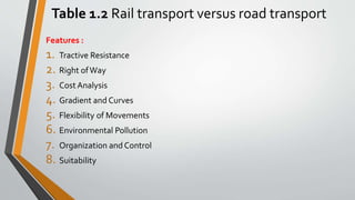
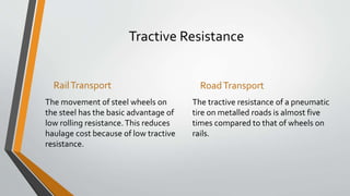
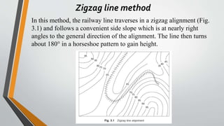
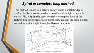
RAILWAY
ENGINEERING
SATISH CHANDRA
Professor, Department of Civil Engineering,
Indian Institute ofTechnology Roorkee
M.M.AGARWAL
Retired Chief Engineer,
Northern Railways
Prepared by: Malyar Talash
Highway Design Manager/Engineer
University Lecturer
tmalyar@yahoo.com
+93786575033
1.2 Different Modes ofTransport
• Our environment consists of land, air, and water. These media have provided
scope for three modes of transport—land transport, air transport and water
transport.
Rail transport and road transport are the two components of land transport. Each
mode of transport, depending upon its various characteristics, has intrinsic
strengths and weaknesses and can be best used for a particular type of traffic as
given below.
Table 1.2 Rail transport versus road transport
Features :
1. Tractive Resistance
2. Right ofWay
3. Cost Analysis
4. Gradient and Curves
5. Flexibility of Movements
6. Environmental Pollution
7. Organization and Control
8. Suitability
Tractive Resistance
RailTransport
The movement of steel wheels on
the steel has the basic advantage of
low rolling resistance.This reduces
haulage cost because of low tractive
resistance.
RoadTransport
The tractive resistance of a pneumatic
tire on metalled roads is almost five
times compared to that of wheels on
rails.
Right of Way
RailTransport
A railway track is defined on to rails
and I within protected limits.Train
woks as per prescribed schedule and
no other vehicle has the right of way
except at specified level crossing.
RoadTransport
Roads, though having well defined
limits, can be used by any vehicular
traffic and even by pedestrian they
are open to all.
Cost analysis
RailTransport
Owning to the heavy infrastructure,
the initial as well as maintenance
cost of railway line is high.
RoadTransport
The cost of construction and maintenance
of roads is comparatively cheaper.
Gradient and Curves
RailTransport
The gradient of railways tracks are
flatter (normally not more than 1%)
and curves are limited up to only 10
degree on broad gauge.
RoadTransport
Roads are constructed normally with
steeper gradient of up to 4% and relatively
much sharper curves.
Flexibility of Movement
RailTransport
Due to the defined route and
facilitates required for the reception
and dispatch of train, railways can be
used only between fixed points.
RoadTransport
Road transport have much more flexibility
in movement and can provide door-to –
door services.
Environmental Pollution
RailTransport
Railways have minimum adverse
effect on the environment.
RoadTransport
Road transport create comparatively
greater pollution than the railway.
Organization and Control
RailTransport
Railways are government undertaking,
with their own organization.
RoadTransport
Barring member stat government
transport, road transport is managed by
the private sector.
Suitability
RailTransport
Railways are best suited for carrying
heavy goods and large number of
passengers over long distance. .
RoadTransport
Road transport is best suited for carrying
lighter goods and smaller number of
passenger over shorter distance.
RailwayTrack and Gauge
CHAPTER 2
Introduction
Gauge is defined as the minimum distance between two rails. Indian Railways
follows this standard practice and the gauge is measured as the clear
minimum distance between the running faces of the two rails as shown in Fig.
2.1.
2.1 Gauges on World Railways
• Various gauges have been adopted by different railways in the world due to
historical and other considerations.
Type of gauge Gauge
(mm)
Gauge (feet) % ofTotal
Length
Countries
Standard
Gauge
1435 4’ 8.5’’ 62 UK, USA, Canada, Turkey,
Persia and China
Broad Gauge 1676 5’ 6’’ 6 India, Pakistan, Ceylon,
Brazil.Argentina
Broad Gauge 1524 5’ 0’’ 9 Russia, Finland
Cape Gauge 1067 3’ 6’’ 8 Africa, Japan, Java,
Australia, and New Zeeland
Meter Gauge 1000 3’ 3.5’’ 9 India, France, Switzerland
and Argentina
23 various
other Gauges
Different
Gauges
Different
Gauges
6 Various Countries
2.3 Choice of Gauge
The choice of gauge is very limited, as each country has a fixed
gauge and all new railway lines are constructed to adhere to the
standard gauge. However, the following factors theoretically
influence the choice of the gauge.
I. Cost consideration
II. Traffic Consideration
III.Physical Features of the Country
IV.Uniformity of Gauge
Choice of Gauge
Cost Considerations
There is only a marginal increase in the cost of the track
if a wider gauge is adopted. In this connection, the
following points are important.
(a) There is a proportional increase in the cost of
acquisition of land, earthwork, rails, sleepers, ballast, and
other track items when constructing a wider gauge.
(b) The cost of building bridges, culverts, and tunnels
increases only marginally due to a wider gauge.
(c) The cost of constructing station buildings, platforms,
staff quarters, level crossings, signals, etc. associated
with the railway network is more or less the same for all
gauges.
(d) The cost of rolling stock is independent of the gauge
of the track for carrying the same volume of traffic.
Traffic Considerations
The volume of traffic depends upon the size of wagons
and the speed and hauling capacity of the train.
(a) As a wider gauge can carry larger wagons and
coaches, it can theoretically carry more traffic.
(b) A wider gauge has a greater potential at higher
speeds, because speed is a function of the diameter of the
wheel, which in turn is limited by the width of the gauge.
(c) The type of traction and signaling equipment required
are independent of the gauge.
Choice of Gauge
Physical Features of the
Country
It is possible to adopt steeper gradients and sharper
curves for a narrow gauge as compared to a wider
gauge.
Uniformity of Gauge
The existence of a uniform gauge in a country
enables smooth, speedy, and efficient operation of
trains. Therefore a single gauge should be adopted
irrespective of the minor advantages of a wider
gauge and the few limitations of a narrower gauge.
2.4 Problems Caused by Change of Gauge
• Inconvenience to Passengers
• Difficulty in Trans-shipment of Goods
• Inefficient Use of Rolling Stock
• Hindrance to Fast Movement of Goods
and Passenger Traffic
• Additional Facilities at Stations and Yards
• Difficulties in Balanced Economic Growth
• Difficulties in Future Gauge Conversion
Projects
Alignment of Railway Lines
CHAPTER 3
Introduction
Alignment of railway line refers to the direction and position
given to the center line of the railway track on the ground in the
horizontal and vertical planes. Horizontal alignment means the
direction of the railway track in the plan including the straight
path and the curves it follows.
3.1 Importance of Good Alignment
A new railway line should be aligned carefully after proper
considerations, as improper alignment may ultimately prove
to be more costly and may not be able to fulfill the desired
objectives. Railway line constructions are capital-intensive
projects, once constructed, it is very difficult to change the
alignment of a railway line because of the costly structures
involved, difficulty in getting additional land for the new
alignment, and such other considerations.
3.2 Basic Requirements of an Ideal
Alignment
• Purpose of the New Railway Line
• Integrated Development
• Economic Considerations
• Maximum Safety and Comfort
• Aesthetic Considerations
Basic Requirements of an Ideal Alignment
Purpose of the New Railway
Line
The alignment of a new railway line should
serve the basic purpose for which the railway
line is being constructed. As brought out
earlier, the purpose may include strategic
considerations, political considerations,
developing of backward areas, connecting
new trade centres, and shortening existing rail
lines.
Integrated Development
The new railway line should fit in with the
general planning and form a part of the
integrated development of the country.
Basic Requirements of an Ideal Alignment
Economic Considerations
• Shortest route
• Construction and maintenance
cost
• Minimum operational expenses
Maximum Safety and Comfort
The alignment should be such that it
provides maximum safety and
comfort to the travelling public. This
can be achieved by designing curves
with proper transition lengths,
providing vertical curves for
gradients, and incorporating other
such technical features.
Basic Requirements of an Ideal Alignment
Aesthetic Considerations
While deciding the alignment, aesthetic aspects should also be given
due weightage. A journey by rail should be visually pleasing. This
can be done by avoiding views of borrow pits and passing the
alignment through natural and beautiful surroundings with scenic
beauty.
3.3 Selection of a Good Alignment
Normally, a direct straight route connecting two points is the shortest
and most economical route for a railway line, but there are practical
problems and other compulsions which necessitate deviation from
this route. The various factors involved is the selection of a good
alignment for a railway line are given below.
3.3 Selection of a Good Alignment
• Topography of the country
• Plane Alignment
• Valley Alignment
• Cross Country Alignment
• Mountain Alignment
• Zigzag Line Method
• Switch-Back Method
• Spiral or Complete Loop
Method
• Choice of Gauge
• Obligatory or Controlling Points
• Important Cities and Towns
• Major Bridges and river
Crossing
• Existing Passes and saddle in
Hilly Terrain
• Site for Tunnels
Zigzag line method
In this method, the railway line traverses in a zigzag alignment (Fig.
3.1) and follows a convenient side slope which is at nearly right
angles to the general direction of the alignment. The line then turns
about 180° in a horseshoe pattern to gain height.
Switch-back method
In the case of steep side slopes, a considerable gain in elevation is
accomplished the switch-back method (Fig. 3.2). This method
involves a reversal of direction achieved by a switch, for which the
train has to necessarily 42 Railway Engineering stop. The switch
point is normally located in a station yard. In Fig. 3.2, A and B are
two switches and A1 and B1 are two buffer stops. A train coming
from D will stop at B1 and move in back gear to line BA. It will stop
at A1 again and then follow the line AC.
Switch-back method
Spiral or complete loop method
This method is used in a narrow valley where a small bridge or
viaduct has been constructed at a considerable height to span the
valley (Fig. 3.3). In this case, normally a complete loop of the
railway line is constructed, so that the line crosses the same point a
second time at a height through a flyover or a tunnel.
Geometrical Standards
• Geological Formation
• Effect of Flood and Climate
• Position of Roads and Road
Crossings
• Proximity of Labor and
Material
• Location of Railway Stations
and Yards
• Religious and Historical
Monuments
• Cost Considerations
• Traffic Considerations
• Economic Considerations
• Political Considerations
3.4 Mountain Railways
There are few hills or mountains that have been connected by
railway lines. Some of the important features of these mountain
railways are the following.
Mountain Railways
Gradients
The gradients of mountain
tracks are very steep. Normally
tracks with gradients of 3% or
more are considered mountain
tracks.
Gauge
Normally narrow gauges with
gauge widths of 762 mm or 610
mm are adopted for mountain
railways.
Mountain Railways
Curvature
The curvature of mountain
tracks is very sharp. Curvatures
of up to 40° are normally
adopted.
Alignment
Mountain alignment is quite
zigzag and not straight in order
to gain heights easily. The type
of alignments normally followed
are zigzag, switch-back, and
spiral.
Mountain Railways
Purpose
Mountain railways have mostly
been constructed for tourist
traffic. In some cases, they may
be constructed for exploiting
hinterland or new areas.
Cost considerations
The cost of construction of mountain
railways is quite high because of the
need for a large number of bridges and
heavy earthwork. The cost, however,
gets considerably reduced by adopting
a smaller gauge, narrow gauge (0.762
m or 0.61 m), and then it is possible to
have very steep gradients and sharp
curvature.
3.5 Rack Railways
In the case of very steep gradients, much steeper than 3%, it
becomes difficult for a locomotive to pull the train load and hence is
possible for the train slide down or slip back along the down grade.
The rack railway system consists of three rails, i.e., one extra toothed
rail in the middle in addition to two normal rails. The locomotive
also has a toothed pinion wheel whose teeth fit into the grooves of
the central toothed rail. This locking arrangement helps to haul the
train load and does not let the locomotive slip back. such as the Fell
system, Abt system, Riggenbach system, and Marsh system, each
with its own characteristics. With the help of this rack and pinion
system, it is possible to move trains even on very steep gradients
such as 1 in 5.
Engineering Surveys and
Construction of New Lines
CHAPTER 4
Introduction
The construction of a new railway line is a capital-intensive project
and each kilometre of a new railway line costs depending upon the
topography of the area, the standard of construction, and such other
features. It is, therefore, natural that a lot of thought be given when
making a final decision as to whether a new railway line is at all
necessary or not.
4.1 Need for Construction of a New Railway
Line
The need for construction of a new railway line arises because of
one or more of the following considerations.
a. Strategic Reasons
b.Political Reason
c. Development of Backward areas
d.To connect new Trade Center
e. To Shorten the existing rail Tack
4.2 Preliminary Investigations for a New
Railway Line
The railway administration determine how the proposed line will fit in
with the general scheme of future railway development. The
preliminary investigations are normally based on a careful study of the
following:
(a) Existing topo sheets and other maps of the area
(b) Published figures of trade and population of the area to be served
(c) Statistical data of existing railway lines in similar terrain in other
areas
As a result of these investigations, it becomes possible to decide whether
or not the new railway line is required and surveys should then be
undertaken to get more details of the new line being contemplated.
4.3 Types of Surveys
Once a decision has been taken during preliminary investigations
about the general feasibility and desirability of a railway line,
surveys are undertaken before the construction of the new line. The
following types of surveys are normally conducted:
(a) Traffic survey
(b) Reconnaissance survey
(c) Preliminary survey
(d) Final location survey
The details of these surveys are discussed in the following sections.
4.4Traffic Survey
Traffic survey includes a detailed study of the traffic conditions in the area with
a view to determine the
(a) most promising route for the railway in the area,
(b) possible traffic the railway line will carry, and
(c) standard of railway line to be followed.
Traffic surveys are normally undertaken in conjunction with reconnaissance or
preliminary engineering surveys so that the technical feasibility and relative
costs of alternative proposals can be formulated. The traffic survey team should
work in close cooperation with the engineering survey team. The survey team
should visit all trade centers in the area and consult local bodies, state
governments, and prominen citizens regarding trade and industry and propose
the most suitable alignment for the new line.
4.4Traffic Survey
Traffic survey consists of an economic study of the area keeping in mind the
following considerations, information on which should be collected in detail:
(a) Human resources
(b) Agricultural and mineral resources
(c) Pattern of trade and commerce
(d) Industries located and projected
(e) Prospects of tourist traffic
(f) Existing transport facilities
(g) Locations of important government and private offices
(h) Planning for economic development of the area
4.4Traffic Survey
The traffic survey team should make an assessment of the traffic
likely to be carried by to the new line. While carrying out the survey,
details of traffic likely to be offered by various government
organizations, public bodies, or private enterprises should be
gathered. At the end of the survey, a report should be formulated by
the officer-in-charge of the survey. The formation of the report is
governed largely by the nature of the terms of reference and the
investigations made. The traffic survey report should normally
contain the following information:
(a) History of the proposal and terms of
reference
(b) General description
(c) Potentials and prospects
(d) Industrial and economic development and
traffic projections
(e) Population projection and volume of
passenger traffic
(f) Existing rates and rates to be charged
(g) Location of route or routes examined,
alternate routes, and possible extensions
(h) Station sites and their importance
(i) Train services, section capacity, and various
alternative ways of increasing capacity
(j) Coaching earnings
(k) Goods earnings
(l) Working expenses and net receipts
(m) Engineering features
(n) Telecommunication facilities
(o) Financial appraisal
(p) Conclusions and recommendations
4.5 Reconnaissance Survey
This survey consists of a rapid and rough investigation of the area
with a view to determine the technical feasibility of the proposal as
well as the rough cost of one or more alternatives to the new line.
The reconnaissance survey (RECCE) is normally based on
contoured survey maps and other data already available without
carrying out detailed investigations in the field. With the help of the
maps, different alternative alignments of the new line are studied.
The general topography of the country is studied by the survey team
and then field data are collected.
4.5.1 Survey Instruments
The reconnaissance survey is mostly conducted using survey instruments
that rapidly measure approximate distances and heights. The survey
instruments used are the following:
• Prismatic compass To get magnetic bearings of the proposed alignment.
• Aneroid barometer To ensure relative heights of various points.
• Abney level or hand level or clinometer To measure the gradients or
angles of slopes.
• Binocular To view the physical features.
• Pedometer To get an idea of the total length traversed while walking.
4.5.3 Field Data
The following field data are collected during the reconnaissance survey.
(a) General topography of the country
(b) Approximate heights of the different points falling on the alignment
(c) Positions of rivers, streams, and some hydrological details of the same
(d) Positions of roads and highways
(e) Nature of soil at different places
(f) Rough location of various station sites
(g) Controlling points on the alignment, through which the railway line must
pass
(h) Facilities for construction
4.6 Preliminary Survey
The preliminary survey consists of a detailed instrumental examination of the
route to be selected as a result of the reconnaissance survey in order to
estimate the cost of the proposed railway line. Based on the preliminary and
traffic survey reports, the railway administration decides whether or not the
proposed railway line is to be constructed.
Rails
CHAPTER 6
Sleepers
CHAPTER 7
Ballast
CHAPTER 8
Creep of Rails
CHAPTER 11
Geometric Design of Truck
CHAPTER 12
Introduction
The geometric design of a railway track includes all those parameters which
determine or affect the geometry of the track.These parameters are as
follows.
1. Gradients in the track, including grade compensation, rising gradient, and
falling gradient.
2. Curvature of the track, including horizontal and vertical curves, transition
curves, sharpness of the curve in terms of radius or degree of the curve, cant or
superelevation on curves, etc.
3. Alignment of the track, including straight as well as curved alignment.
It is very important for tracks to have proper geometric design in order to
ensure the safe and smooth running of trains at maximum permissible speeds,
carrying the heaviest axle loads.The speed and axle load of the train are very
important and sometimes are also included as parameters to be considered
while arriving at the geometric design of the track.
12.1 Necessity for Geometric Design
The need for proper geometric design of a track arises because of the following
considerations
(a)To ensure the smooth and safe running of trains
(b)To achieve maximum speeds
(c)To carry heavy axle loads
(d)To avoid accidents and derailments due to a defective permanent way
(e)To ensure that the track requires least maintenance.
(f) For good aesthetics
12.2 Details of Geometric Design ofTrack
12.3 Gradients
Gradients are provided to negotiate the rise or fall in the level of the railway
track. A rising gradient is one in which the track rises in the direction of the
movement of traffic and a down or falling gradient is one in which the track
loses elevation in the direction of the movement of traffic.
A gradient is normally represented by the distance travelled for a rise or fall of
one unit. Sometimes the gradient is indicated as per cent rise or fall. For
example, if there is a rise of 1 m in 400 m, the gradient is 1 in 400 or 0.25%, as
shown in Fig. 12.1.
Cont…
Gradients are provided to meet the following objectives.
(a)To reach various stations at different elevations
(b)To follow the natural contours of the ground to the extent possible
(c)To reduce the cost of earthwork.
The following types of gradients are used on the railways.
(a) Ruling gradient
(b) Pusher or helper gradient
(c) Momentum gradient
(d) Gradients in station yards
12.3.1 Ruling Gradient
The ruling gradient is the steepest gradient that exists in a section. It
determines the maximum load that can be hauled by a locomotive on that
section.While deciding the ruling gradient of a section, it is not only the
severity of the gradient but also its length as well as its position with respect to
the gradients on both sides that have to be taken into consideration.
• In plain terrain: 1 in 150 to 1 in 250
• In hilly terrain: 1 in 100 to 1 in 150
Once a ruling gradient has been specified for a section, all other gradients
provided in that section should be flatter than the ruling gradient after making
due compensation for curvature.
12.3.2 Pusher or Helper Gradient
In hilly areas, the rate of rise of the terrain becomes very important when
trying to reduce the length of the railway line and, therefore, sometimes
gradients steeper than the ruling gradient are provided to reduce the overall
cost. In such situations, one locomotive is not adequate to pull the entire load,
and an extra locomotive is required.
When the gradient of the ensuing section is so steep as to necessitate the use
of an extra engine for pushing the train, it is known as a pusher or helper
gradient.
12.3.3 Momentum Gradient
The momentum gradient is steeper than the ruling gradient and
can be overcome by a train because of the momentum it gathers
while running on the section. In valleys, a falling gradient is
sometimes followed by a rising gradient. In such a situation, a train
coming down a falling gradient acquires good speed and
momentum, which gives additional kinetic energy to the train and
allows it to negotiate gradients steeper than the ruling gradient. In
sections with momentum gradients there are no obstacles
provided in the form of signals, etc., which may bring the train to a
critical juncture.
12.3.4 Gradients in StationYards
The gradients in station yards are quite flat due to the following reasons.
(a)To prevent standing vehicles from rolling and moving away from the yard due to
the combined effect of gravity and strong winds.
(b)To reduce the additional resistive forces required to start a locomotive to the
extent possible.
It may be mentioned here that generally, yards are not levelled completely and
certain flat gradients are provided in order to ensure good drainage.The maximum
gradient prescribed in station yards on Indian Railways is 1 in 400, while the
recommended gradient is 1 in 1000.
12.4 Grade Compensation on Curves
Curves provide extra resistance to the movement of trains. As a result, gradients are
compensated to the following extent on curves
(a) On BG tracks, 0.04% per degree of the curve or 70/R, whichever is minimum
(b) On MG tracks, 0.03% per degree of curve or 52.5/R, whichever is minimum
(c) On NG tracks, 0.02% per degree of curve or 35/R, whichever is minimum where R is
the radius of the curve in meters.The gradient of a curved portion of the section
should be flatter than the ruling gradient because of the extra resistance offered by
the curve.
Example
Example 12.1 Find the steepest gradient on a 2° curve for a BG line with a ruling
gradient of 1 in 200.
Solution
(i) Ruling gradient = 1 in 200 = 0.5%
(ii) Compensation for a 2° curve = 0.04 × 2 = 0.08%
(iii) Compensated gradient = 0.5 – 0.08 = 0.42% = 1 in 238
The steepest gradient on the curved track is 1 in 238.
Curve and Superelevation
CHAPTER 13
Introduction
Curves are introduced on a railway track to bypass obstacles, to provide longer
and easily traversed gradients, and to pass a railway line through obligatory or
desirable locations. Horizontal curves are provided when a change in the
direction of the track is required and vertical curves are provided at points
where two gradients meet or where a gradient meets level ground.To provide
a comfortable ride on a horizontal curve, the level of the outer rail is raised
above the level of the inner rail.This is known as superelevation.
Radius or degree of a curve
A curve is defined either by its radius or by its degree.The
degree of a curve (D) is the angle subtended at its center by a
30.5-m or 100-ft chord.The value of the degree of the curve can
be determined as indicated below.
Circumference of a circle = 2πR
Angle subtended at the center by a circle with this circumference = 360°
13.2 Superelevation
The following terms are frequently used in the design of horizontal curves.
Superelevation or cant (Ca) is the difference in height between the outer and
the inner rail on a curve. It is provided by gradually lifting the outer rail above
the level of the inner rail.The inner rail is taken as the reference
rail and is normally maintained at its original level.The inner rail is also known
as the gradient rail.The main functions of superelevation are the following.
(a)To ensure a better distribution of load on both rails
(b)To reduce the wear and tear of the rails and rolling stock
(c)To neutralize the effect of lateral forces
(d)To provide comfort to passengers
Equilibrium speed
When the speed of a vehicle negotiating a curved track is such that
the resultant force of the weight of the vehicle and of radial
acceleration is perpendicular to the plane of the rails, the vehicle is
not subjected to any unbalanced radial acceleration and is said to
be in equilibrium.This particular speed is called the equilibrium
speed.The equilibrium speed, as such, is the speed at which the
effect of the centrifugal force is completely balanced by the cant
provided.
Maximum permissible speed
This is the highest speed permitted to a train on a curve taking into
consideration the radius of curvature, actual cant, cant deficiency,
cant excess, and the length of transition. On cruves where the
maximum permissible speed is less than the maximum sectional
speed of the section of the line, permanent speed restriction
becomes necessary.
Cont…
• Cant deficiency Cant deficiency (Cd) occurs when a train travels around a
curve at a speed higher than the equilibrium speed. It is the difference
between the theoretical cant required for such high speeds and the actual
cant provided.
• Cant excess Cant excess (Ce) occurs when a train travels around a curve at a
speed lower than the equilibrium speed. It is the difference between the
actual cant provided and the theoretical cant required for such a low speed.
Cont…
• Cant gradient and cant deficiency gradient These indicate the increase or
decrease in the cant or the deficiency of cant in a given length of transition.
A gradient of 1 in 1000 means that a cant or a deficiency of cant of 1 mm is
attained or lost in every 1000 mm of transition length.
• Rate of change of cant or cant deficiency This is the rate at which cant
deficiency increases while passing over the transition curve, e.g., a rate of 35
mm per second means that a vehicle will experience a change in cant or a
cant deficiency of 35 mm in each second of travel over the transition when
travelling at the maximum permissible speed.
13.2.5 MaximumValue of Superelevation
The maximum value of superelevation has been laid down based on
experiments carried out in Europe on a standard gauge for the overturning
velocity, taking into consideration the track maintenance standards.The
maximum value of the superelevation generally adopted around many
railways around the world is 1/10th to 1/12th of the gauge.The values of
maximum superelevation prescribed on Indian Railways are given inTable
13.2.
Table 13.2.
No Gauge Group LimitingValue of Cant (mm)
Under Normal
Condition
With Special
Permission of
CE
1 BG A 165 185
2 BG B and C 165 -
3 BG D and E 140 -
4 MG - 90 100
5 NG - 65 75
13.2.7 Negative Superelevation
When the main line lies on a curve and has a turnout of contrary
flexure leading to a branch line, the superelevation necessary for
the average speed of trains running over the main line curve cannot
be provided. In Fig. 13.9, AB, which is the outer rail of the main line
curve, must be higher than CD. For the branch line, however, CF
should be higher than AE or point C should be higher than point A.
These two contradictory conditions cannot be met within one
layout. In such cases, the branch line curve has a negative
superelevation and, therefore, speeds on both tracks must be
restricted, particularly on the branch line.
Fig. 13.9 Negative superelevation
Points and Crossings
CHAPTER 14
Track Maintenance
CHAPTER 18
Track Drainage
CHAPTER 19
Introduction
Track drainage can be defined as the interception, collection, and disposal of
water from, upon, or under the track. It is accomplished by installing a proper
surface and sub-surface drainage system.
Need of Proper Drainage
• Settlement of Embankment
• Reduction in bearing capacity
• Failure of Embankment
• Formation of Ballast Pocket
• Shrinkage and Cracking of Bank
• Adverse affect of black cotton soil
• Formation of Slash
Locomotives and Other Rolling Stock
CHAPTER 24
Railway Station and Yard
CHAPTER 26
Equipment at Railway Station
CHAPTER 27

Railway engineering

  • 1.
    RAILWAY ENGINEERING SATISH CHANDRA Professor, Departmentof Civil Engineering, Indian Institute ofTechnology Roorkee M.M.AGARWAL Retired Chief Engineer, Northern Railways Prepared by: Malyar Talash Highway Design Manager/Engineer University Lecturer tmalyar@yahoo.com +93786575033
  • 2.
    1.2 Different ModesofTransport • Our environment consists of land, air, and water. These media have provided scope for three modes of transport—land transport, air transport and water transport. Rail transport and road transport are the two components of land transport. Each mode of transport, depending upon its various characteristics, has intrinsic strengths and weaknesses and can be best used for a particular type of traffic as given below.
  • 3.
    Table 1.2 Railtransport versus road transport Features : 1. Tractive Resistance 2. Right ofWay 3. Cost Analysis 4. Gradient and Curves 5. Flexibility of Movements 6. Environmental Pollution 7. Organization and Control 8. Suitability
  • 4.
    Tractive Resistance RailTransport The movementof steel wheels on the steel has the basic advantage of low rolling resistance.This reduces haulage cost because of low tractive resistance. RoadTransport The tractive resistance of a pneumatic tire on metalled roads is almost five times compared to that of wheels on rails.
  • 5.
    Right of Way RailTransport Arailway track is defined on to rails and I within protected limits.Train woks as per prescribed schedule and no other vehicle has the right of way except at specified level crossing. RoadTransport Roads, though having well defined limits, can be used by any vehicular traffic and even by pedestrian they are open to all.
  • 6.
    Cost analysis RailTransport Owning tothe heavy infrastructure, the initial as well as maintenance cost of railway line is high. RoadTransport The cost of construction and maintenance of roads is comparatively cheaper.
  • 7.
    Gradient and Curves RailTransport Thegradient of railways tracks are flatter (normally not more than 1%) and curves are limited up to only 10 degree on broad gauge. RoadTransport Roads are constructed normally with steeper gradient of up to 4% and relatively much sharper curves.
  • 8.
    Flexibility of Movement RailTransport Dueto the defined route and facilitates required for the reception and dispatch of train, railways can be used only between fixed points. RoadTransport Road transport have much more flexibility in movement and can provide door-to – door services.
  • 9.
    Environmental Pollution RailTransport Railways haveminimum adverse effect on the environment. RoadTransport Road transport create comparatively greater pollution than the railway.
  • 10.
    Organization and Control RailTransport Railwaysare government undertaking, with their own organization. RoadTransport Barring member stat government transport, road transport is managed by the private sector.
  • 11.
    Suitability RailTransport Railways are bestsuited for carrying heavy goods and large number of passengers over long distance. . RoadTransport Road transport is best suited for carrying lighter goods and smaller number of passenger over shorter distance.
  • 13.
  • 14.
    Introduction Gauge is definedas the minimum distance between two rails. Indian Railways follows this standard practice and the gauge is measured as the clear minimum distance between the running faces of the two rails as shown in Fig. 2.1.
  • 15.
    2.1 Gauges onWorld Railways • Various gauges have been adopted by different railways in the world due to historical and other considerations. Type of gauge Gauge (mm) Gauge (feet) % ofTotal Length Countries Standard Gauge 1435 4’ 8.5’’ 62 UK, USA, Canada, Turkey, Persia and China Broad Gauge 1676 5’ 6’’ 6 India, Pakistan, Ceylon, Brazil.Argentina Broad Gauge 1524 5’ 0’’ 9 Russia, Finland Cape Gauge 1067 3’ 6’’ 8 Africa, Japan, Java, Australia, and New Zeeland Meter Gauge 1000 3’ 3.5’’ 9 India, France, Switzerland and Argentina 23 various other Gauges Different Gauges Different Gauges 6 Various Countries
  • 16.
    2.3 Choice ofGauge The choice of gauge is very limited, as each country has a fixed gauge and all new railway lines are constructed to adhere to the standard gauge. However, the following factors theoretically influence the choice of the gauge. I. Cost consideration II. Traffic Consideration III.Physical Features of the Country IV.Uniformity of Gauge
  • 17.
    Choice of Gauge CostConsiderations There is only a marginal increase in the cost of the track if a wider gauge is adopted. In this connection, the following points are important. (a) There is a proportional increase in the cost of acquisition of land, earthwork, rails, sleepers, ballast, and other track items when constructing a wider gauge. (b) The cost of building bridges, culverts, and tunnels increases only marginally due to a wider gauge. (c) The cost of constructing station buildings, platforms, staff quarters, level crossings, signals, etc. associated with the railway network is more or less the same for all gauges. (d) The cost of rolling stock is independent of the gauge of the track for carrying the same volume of traffic. Traffic Considerations The volume of traffic depends upon the size of wagons and the speed and hauling capacity of the train. (a) As a wider gauge can carry larger wagons and coaches, it can theoretically carry more traffic. (b) A wider gauge has a greater potential at higher speeds, because speed is a function of the diameter of the wheel, which in turn is limited by the width of the gauge. (c) The type of traction and signaling equipment required are independent of the gauge.
  • 18.
    Choice of Gauge PhysicalFeatures of the Country It is possible to adopt steeper gradients and sharper curves for a narrow gauge as compared to a wider gauge. Uniformity of Gauge The existence of a uniform gauge in a country enables smooth, speedy, and efficient operation of trains. Therefore a single gauge should be adopted irrespective of the minor advantages of a wider gauge and the few limitations of a narrower gauge.
  • 19.
    2.4 Problems Causedby Change of Gauge • Inconvenience to Passengers • Difficulty in Trans-shipment of Goods • Inefficient Use of Rolling Stock • Hindrance to Fast Movement of Goods and Passenger Traffic • Additional Facilities at Stations and Yards • Difficulties in Balanced Economic Growth • Difficulties in Future Gauge Conversion Projects
  • 20.
    Alignment of RailwayLines CHAPTER 3
  • 21.
    Introduction Alignment of railwayline refers to the direction and position given to the center line of the railway track on the ground in the horizontal and vertical planes. Horizontal alignment means the direction of the railway track in the plan including the straight path and the curves it follows.
  • 22.
    3.1 Importance ofGood Alignment A new railway line should be aligned carefully after proper considerations, as improper alignment may ultimately prove to be more costly and may not be able to fulfill the desired objectives. Railway line constructions are capital-intensive projects, once constructed, it is very difficult to change the alignment of a railway line because of the costly structures involved, difficulty in getting additional land for the new alignment, and such other considerations.
  • 23.
    3.2 Basic Requirementsof an Ideal Alignment • Purpose of the New Railway Line • Integrated Development • Economic Considerations • Maximum Safety and Comfort • Aesthetic Considerations
  • 24.
    Basic Requirements ofan Ideal Alignment Purpose of the New Railway Line The alignment of a new railway line should serve the basic purpose for which the railway line is being constructed. As brought out earlier, the purpose may include strategic considerations, political considerations, developing of backward areas, connecting new trade centres, and shortening existing rail lines. Integrated Development The new railway line should fit in with the general planning and form a part of the integrated development of the country.
  • 25.
    Basic Requirements ofan Ideal Alignment Economic Considerations • Shortest route • Construction and maintenance cost • Minimum operational expenses Maximum Safety and Comfort The alignment should be such that it provides maximum safety and comfort to the travelling public. This can be achieved by designing curves with proper transition lengths, providing vertical curves for gradients, and incorporating other such technical features.
  • 26.
    Basic Requirements ofan Ideal Alignment Aesthetic Considerations While deciding the alignment, aesthetic aspects should also be given due weightage. A journey by rail should be visually pleasing. This can be done by avoiding views of borrow pits and passing the alignment through natural and beautiful surroundings with scenic beauty.
  • 27.
    3.3 Selection ofa Good Alignment Normally, a direct straight route connecting two points is the shortest and most economical route for a railway line, but there are practical problems and other compulsions which necessitate deviation from this route. The various factors involved is the selection of a good alignment for a railway line are given below.
  • 28.
    3.3 Selection ofa Good Alignment • Topography of the country • Plane Alignment • Valley Alignment • Cross Country Alignment • Mountain Alignment • Zigzag Line Method • Switch-Back Method • Spiral or Complete Loop Method • Choice of Gauge • Obligatory or Controlling Points • Important Cities and Towns • Major Bridges and river Crossing • Existing Passes and saddle in Hilly Terrain • Site for Tunnels
  • 29.
    Zigzag line method Inthis method, the railway line traverses in a zigzag alignment (Fig. 3.1) and follows a convenient side slope which is at nearly right angles to the general direction of the alignment. The line then turns about 180° in a horseshoe pattern to gain height.
  • 30.
    Switch-back method In thecase of steep side slopes, a considerable gain in elevation is accomplished the switch-back method (Fig. 3.2). This method involves a reversal of direction achieved by a switch, for which the train has to necessarily 42 Railway Engineering stop. The switch point is normally located in a station yard. In Fig. 3.2, A and B are two switches and A1 and B1 are two buffer stops. A train coming from D will stop at B1 and move in back gear to line BA. It will stop at A1 again and then follow the line AC.
  • 31.
  • 32.
    Spiral or completeloop method This method is used in a narrow valley where a small bridge or viaduct has been constructed at a considerable height to span the valley (Fig. 3.3). In this case, normally a complete loop of the railway line is constructed, so that the line crosses the same point a second time at a height through a flyover or a tunnel.
  • 33.
    Geometrical Standards • GeologicalFormation • Effect of Flood and Climate • Position of Roads and Road Crossings • Proximity of Labor and Material • Location of Railway Stations and Yards • Religious and Historical Monuments • Cost Considerations • Traffic Considerations • Economic Considerations • Political Considerations
  • 34.
    3.4 Mountain Railways Thereare few hills or mountains that have been connected by railway lines. Some of the important features of these mountain railways are the following.
  • 35.
    Mountain Railways Gradients The gradientsof mountain tracks are very steep. Normally tracks with gradients of 3% or more are considered mountain tracks. Gauge Normally narrow gauges with gauge widths of 762 mm or 610 mm are adopted for mountain railways.
  • 36.
    Mountain Railways Curvature The curvatureof mountain tracks is very sharp. Curvatures of up to 40° are normally adopted. Alignment Mountain alignment is quite zigzag and not straight in order to gain heights easily. The type of alignments normally followed are zigzag, switch-back, and spiral.
  • 37.
    Mountain Railways Purpose Mountain railwayshave mostly been constructed for tourist traffic. In some cases, they may be constructed for exploiting hinterland or new areas. Cost considerations The cost of construction of mountain railways is quite high because of the need for a large number of bridges and heavy earthwork. The cost, however, gets considerably reduced by adopting a smaller gauge, narrow gauge (0.762 m or 0.61 m), and then it is possible to have very steep gradients and sharp curvature.
  • 38.
    3.5 Rack Railways Inthe case of very steep gradients, much steeper than 3%, it becomes difficult for a locomotive to pull the train load and hence is possible for the train slide down or slip back along the down grade. The rack railway system consists of three rails, i.e., one extra toothed rail in the middle in addition to two normal rails. The locomotive also has a toothed pinion wheel whose teeth fit into the grooves of the central toothed rail. This locking arrangement helps to haul the train load and does not let the locomotive slip back. such as the Fell system, Abt system, Riggenbach system, and Marsh system, each with its own characteristics. With the help of this rack and pinion system, it is possible to move trains even on very steep gradients such as 1 in 5.
  • 39.
  • 40.
    Introduction The construction ofa new railway line is a capital-intensive project and each kilometre of a new railway line costs depending upon the topography of the area, the standard of construction, and such other features. It is, therefore, natural that a lot of thought be given when making a final decision as to whether a new railway line is at all necessary or not.
  • 41.
    4.1 Need forConstruction of a New Railway Line The need for construction of a new railway line arises because of one or more of the following considerations. a. Strategic Reasons b.Political Reason c. Development of Backward areas d.To connect new Trade Center e. To Shorten the existing rail Tack
  • 42.
    4.2 Preliminary Investigationsfor a New Railway Line The railway administration determine how the proposed line will fit in with the general scheme of future railway development. The preliminary investigations are normally based on a careful study of the following: (a) Existing topo sheets and other maps of the area (b) Published figures of trade and population of the area to be served (c) Statistical data of existing railway lines in similar terrain in other areas As a result of these investigations, it becomes possible to decide whether or not the new railway line is required and surveys should then be undertaken to get more details of the new line being contemplated.
  • 43.
    4.3 Types ofSurveys Once a decision has been taken during preliminary investigations about the general feasibility and desirability of a railway line, surveys are undertaken before the construction of the new line. The following types of surveys are normally conducted: (a) Traffic survey (b) Reconnaissance survey (c) Preliminary survey (d) Final location survey The details of these surveys are discussed in the following sections.
  • 44.
    4.4Traffic Survey Traffic surveyincludes a detailed study of the traffic conditions in the area with a view to determine the (a) most promising route for the railway in the area, (b) possible traffic the railway line will carry, and (c) standard of railway line to be followed. Traffic surveys are normally undertaken in conjunction with reconnaissance or preliminary engineering surveys so that the technical feasibility and relative costs of alternative proposals can be formulated. The traffic survey team should work in close cooperation with the engineering survey team. The survey team should visit all trade centers in the area and consult local bodies, state governments, and prominen citizens regarding trade and industry and propose the most suitable alignment for the new line.
  • 45.
    4.4Traffic Survey Traffic surveyconsists of an economic study of the area keeping in mind the following considerations, information on which should be collected in detail: (a) Human resources (b) Agricultural and mineral resources (c) Pattern of trade and commerce (d) Industries located and projected (e) Prospects of tourist traffic (f) Existing transport facilities (g) Locations of important government and private offices (h) Planning for economic development of the area
  • 46.
    4.4Traffic Survey The trafficsurvey team should make an assessment of the traffic likely to be carried by to the new line. While carrying out the survey, details of traffic likely to be offered by various government organizations, public bodies, or private enterprises should be gathered. At the end of the survey, a report should be formulated by the officer-in-charge of the survey. The formation of the report is governed largely by the nature of the terms of reference and the investigations made. The traffic survey report should normally contain the following information:
  • 47.
    (a) History ofthe proposal and terms of reference (b) General description (c) Potentials and prospects (d) Industrial and economic development and traffic projections (e) Population projection and volume of passenger traffic (f) Existing rates and rates to be charged (g) Location of route or routes examined, alternate routes, and possible extensions (h) Station sites and their importance (i) Train services, section capacity, and various alternative ways of increasing capacity (j) Coaching earnings (k) Goods earnings (l) Working expenses and net receipts (m) Engineering features (n) Telecommunication facilities (o) Financial appraisal (p) Conclusions and recommendations
  • 48.
    4.5 Reconnaissance Survey Thissurvey consists of a rapid and rough investigation of the area with a view to determine the technical feasibility of the proposal as well as the rough cost of one or more alternatives to the new line. The reconnaissance survey (RECCE) is normally based on contoured survey maps and other data already available without carrying out detailed investigations in the field. With the help of the maps, different alternative alignments of the new line are studied. The general topography of the country is studied by the survey team and then field data are collected.
  • 49.
    4.5.1 Survey Instruments Thereconnaissance survey is mostly conducted using survey instruments that rapidly measure approximate distances and heights. The survey instruments used are the following: • Prismatic compass To get magnetic bearings of the proposed alignment. • Aneroid barometer To ensure relative heights of various points. • Abney level or hand level or clinometer To measure the gradients or angles of slopes. • Binocular To view the physical features. • Pedometer To get an idea of the total length traversed while walking.
  • 50.
    4.5.3 Field Data Thefollowing field data are collected during the reconnaissance survey. (a) General topography of the country (b) Approximate heights of the different points falling on the alignment (c) Positions of rivers, streams, and some hydrological details of the same (d) Positions of roads and highways (e) Nature of soil at different places (f) Rough location of various station sites (g) Controlling points on the alignment, through which the railway line must pass (h) Facilities for construction
  • 51.
    4.6 Preliminary Survey Thepreliminary survey consists of a detailed instrumental examination of the route to be selected as a result of the reconnaissance survey in order to estimate the cost of the proposed railway line. Based on the preliminary and traffic survey reports, the railway administration decides whether or not the proposed railway line is to be constructed.
  • 52.
  • 53.
  • 54.
  • 55.
  • 56.
    Geometric Design ofTruck CHAPTER 12
  • 57.
    Introduction The geometric designof a railway track includes all those parameters which determine or affect the geometry of the track.These parameters are as follows. 1. Gradients in the track, including grade compensation, rising gradient, and falling gradient. 2. Curvature of the track, including horizontal and vertical curves, transition curves, sharpness of the curve in terms of radius or degree of the curve, cant or superelevation on curves, etc. 3. Alignment of the track, including straight as well as curved alignment. It is very important for tracks to have proper geometric design in order to ensure the safe and smooth running of trains at maximum permissible speeds, carrying the heaviest axle loads.The speed and axle load of the train are very important and sometimes are also included as parameters to be considered while arriving at the geometric design of the track.
  • 58.
    12.1 Necessity forGeometric Design The need for proper geometric design of a track arises because of the following considerations (a)To ensure the smooth and safe running of trains (b)To achieve maximum speeds (c)To carry heavy axle loads (d)To avoid accidents and derailments due to a defective permanent way (e)To ensure that the track requires least maintenance. (f) For good aesthetics
  • 59.
    12.2 Details ofGeometric Design ofTrack
  • 60.
    12.3 Gradients Gradients areprovided to negotiate the rise or fall in the level of the railway track. A rising gradient is one in which the track rises in the direction of the movement of traffic and a down or falling gradient is one in which the track loses elevation in the direction of the movement of traffic. A gradient is normally represented by the distance travelled for a rise or fall of one unit. Sometimes the gradient is indicated as per cent rise or fall. For example, if there is a rise of 1 m in 400 m, the gradient is 1 in 400 or 0.25%, as shown in Fig. 12.1.
  • 62.
    Cont… Gradients are providedto meet the following objectives. (a)To reach various stations at different elevations (b)To follow the natural contours of the ground to the extent possible (c)To reduce the cost of earthwork. The following types of gradients are used on the railways. (a) Ruling gradient (b) Pusher or helper gradient (c) Momentum gradient (d) Gradients in station yards
  • 63.
    12.3.1 Ruling Gradient Theruling gradient is the steepest gradient that exists in a section. It determines the maximum load that can be hauled by a locomotive on that section.While deciding the ruling gradient of a section, it is not only the severity of the gradient but also its length as well as its position with respect to the gradients on both sides that have to be taken into consideration. • In plain terrain: 1 in 150 to 1 in 250 • In hilly terrain: 1 in 100 to 1 in 150 Once a ruling gradient has been specified for a section, all other gradients provided in that section should be flatter than the ruling gradient after making due compensation for curvature.
  • 64.
    12.3.2 Pusher orHelper Gradient In hilly areas, the rate of rise of the terrain becomes very important when trying to reduce the length of the railway line and, therefore, sometimes gradients steeper than the ruling gradient are provided to reduce the overall cost. In such situations, one locomotive is not adequate to pull the entire load, and an extra locomotive is required. When the gradient of the ensuing section is so steep as to necessitate the use of an extra engine for pushing the train, it is known as a pusher or helper gradient.
  • 65.
    12.3.3 Momentum Gradient Themomentum gradient is steeper than the ruling gradient and can be overcome by a train because of the momentum it gathers while running on the section. In valleys, a falling gradient is sometimes followed by a rising gradient. In such a situation, a train coming down a falling gradient acquires good speed and momentum, which gives additional kinetic energy to the train and allows it to negotiate gradients steeper than the ruling gradient. In sections with momentum gradients there are no obstacles provided in the form of signals, etc., which may bring the train to a critical juncture.
  • 66.
    12.3.4 Gradients inStationYards The gradients in station yards are quite flat due to the following reasons. (a)To prevent standing vehicles from rolling and moving away from the yard due to the combined effect of gravity and strong winds. (b)To reduce the additional resistive forces required to start a locomotive to the extent possible. It may be mentioned here that generally, yards are not levelled completely and certain flat gradients are provided in order to ensure good drainage.The maximum gradient prescribed in station yards on Indian Railways is 1 in 400, while the recommended gradient is 1 in 1000.
  • 67.
    12.4 Grade Compensationon Curves Curves provide extra resistance to the movement of trains. As a result, gradients are compensated to the following extent on curves (a) On BG tracks, 0.04% per degree of the curve or 70/R, whichever is minimum (b) On MG tracks, 0.03% per degree of curve or 52.5/R, whichever is minimum (c) On NG tracks, 0.02% per degree of curve or 35/R, whichever is minimum where R is the radius of the curve in meters.The gradient of a curved portion of the section should be flatter than the ruling gradient because of the extra resistance offered by the curve.
  • 68.
    Example Example 12.1 Findthe steepest gradient on a 2° curve for a BG line with a ruling gradient of 1 in 200. Solution (i) Ruling gradient = 1 in 200 = 0.5% (ii) Compensation for a 2° curve = 0.04 × 2 = 0.08% (iii) Compensated gradient = 0.5 – 0.08 = 0.42% = 1 in 238 The steepest gradient on the curved track is 1 in 238.
  • 69.
  • 70.
    Introduction Curves are introducedon a railway track to bypass obstacles, to provide longer and easily traversed gradients, and to pass a railway line through obligatory or desirable locations. Horizontal curves are provided when a change in the direction of the track is required and vertical curves are provided at points where two gradients meet or where a gradient meets level ground.To provide a comfortable ride on a horizontal curve, the level of the outer rail is raised above the level of the inner rail.This is known as superelevation.
  • 71.
    Radius or degreeof a curve A curve is defined either by its radius or by its degree.The degree of a curve (D) is the angle subtended at its center by a 30.5-m or 100-ft chord.The value of the degree of the curve can be determined as indicated below. Circumference of a circle = 2πR Angle subtended at the center by a circle with this circumference = 360°
  • 73.
    13.2 Superelevation The followingterms are frequently used in the design of horizontal curves. Superelevation or cant (Ca) is the difference in height between the outer and the inner rail on a curve. It is provided by gradually lifting the outer rail above the level of the inner rail.The inner rail is taken as the reference rail and is normally maintained at its original level.The inner rail is also known as the gradient rail.The main functions of superelevation are the following. (a)To ensure a better distribution of load on both rails (b)To reduce the wear and tear of the rails and rolling stock (c)To neutralize the effect of lateral forces (d)To provide comfort to passengers
  • 74.
    Equilibrium speed When thespeed of a vehicle negotiating a curved track is such that the resultant force of the weight of the vehicle and of radial acceleration is perpendicular to the plane of the rails, the vehicle is not subjected to any unbalanced radial acceleration and is said to be in equilibrium.This particular speed is called the equilibrium speed.The equilibrium speed, as such, is the speed at which the effect of the centrifugal force is completely balanced by the cant provided.
  • 75.
    Maximum permissible speed Thisis the highest speed permitted to a train on a curve taking into consideration the radius of curvature, actual cant, cant deficiency, cant excess, and the length of transition. On cruves where the maximum permissible speed is less than the maximum sectional speed of the section of the line, permanent speed restriction becomes necessary.
  • 76.
    Cont… • Cant deficiencyCant deficiency (Cd) occurs when a train travels around a curve at a speed higher than the equilibrium speed. It is the difference between the theoretical cant required for such high speeds and the actual cant provided. • Cant excess Cant excess (Ce) occurs when a train travels around a curve at a speed lower than the equilibrium speed. It is the difference between the actual cant provided and the theoretical cant required for such a low speed.
  • 77.
    Cont… • Cant gradientand cant deficiency gradient These indicate the increase or decrease in the cant or the deficiency of cant in a given length of transition. A gradient of 1 in 1000 means that a cant or a deficiency of cant of 1 mm is attained or lost in every 1000 mm of transition length. • Rate of change of cant or cant deficiency This is the rate at which cant deficiency increases while passing over the transition curve, e.g., a rate of 35 mm per second means that a vehicle will experience a change in cant or a cant deficiency of 35 mm in each second of travel over the transition when travelling at the maximum permissible speed.
  • 78.
    13.2.5 MaximumValue ofSuperelevation The maximum value of superelevation has been laid down based on experiments carried out in Europe on a standard gauge for the overturning velocity, taking into consideration the track maintenance standards.The maximum value of the superelevation generally adopted around many railways around the world is 1/10th to 1/12th of the gauge.The values of maximum superelevation prescribed on Indian Railways are given inTable 13.2.
  • 79.
    Table 13.2. No GaugeGroup LimitingValue of Cant (mm) Under Normal Condition With Special Permission of CE 1 BG A 165 185 2 BG B and C 165 - 3 BG D and E 140 - 4 MG - 90 100 5 NG - 65 75
  • 80.
    13.2.7 Negative Superelevation Whenthe main line lies on a curve and has a turnout of contrary flexure leading to a branch line, the superelevation necessary for the average speed of trains running over the main line curve cannot be provided. In Fig. 13.9, AB, which is the outer rail of the main line curve, must be higher than CD. For the branch line, however, CF should be higher than AE or point C should be higher than point A. These two contradictory conditions cannot be met within one layout. In such cases, the branch line curve has a negative superelevation and, therefore, speeds on both tracks must be restricted, particularly on the branch line.
  • 81.
    Fig. 13.9 Negativesuperelevation
  • 82.
  • 83.
  • 84.
  • 85.
    Introduction Track drainage canbe defined as the interception, collection, and disposal of water from, upon, or under the track. It is accomplished by installing a proper surface and sub-surface drainage system.
  • 86.
    Need of ProperDrainage • Settlement of Embankment • Reduction in bearing capacity • Failure of Embankment • Formation of Ballast Pocket • Shrinkage and Cracking of Bank • Adverse affect of black cotton soil • Formation of Slash
  • 87.
    Locomotives and OtherRolling Stock CHAPTER 24
  • 88.
    Railway Station andYard CHAPTER 26
  • 89.
    Equipment at RailwayStation CHAPTER 27