Downloaded 1,480 times
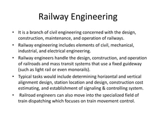
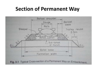


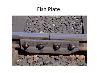


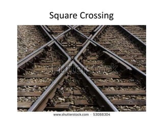
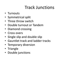
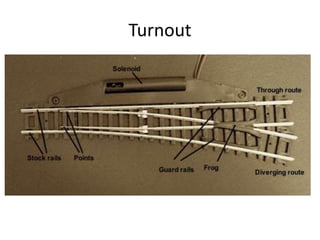
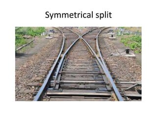

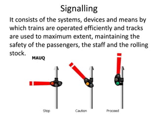
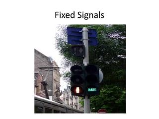


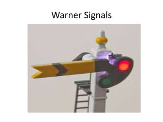
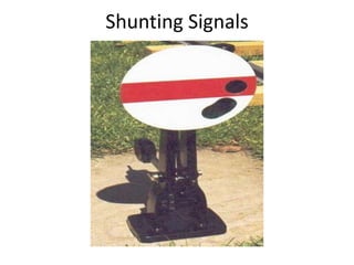
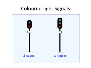


Railway engineering involves the design, construction, and operation of railroads and mass transit systems. It is a branch of civil engineering that deals with track design, station layout, signaling systems, and train movement control. Typical tasks for railway engineers include determining horizontal and vertical alignment, estimating construction costs, and establishing signaling and control systems. Railway tracks consist of rails laid on sleepers embedded in ballast. Points and crossings allow trains to switch tracks. A variety of signals are used to safely direct train movement.


