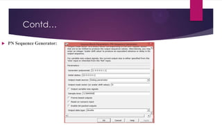
Downloaded 119 times

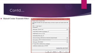
![Raised Cosine Filter
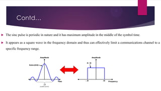
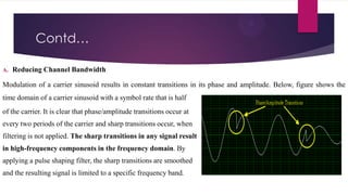
If the transmitted signal is restricted to a certain bandwidth, then infinite bandwidth associated with a rectangular
pulse is not acceptable. The bandwidth of the rectangular pulse can be limited, however, by forcing it to pass through
a low-pass filter. The act of filtering the pulse causes its shape to change from purely rectangular to a smooth contour
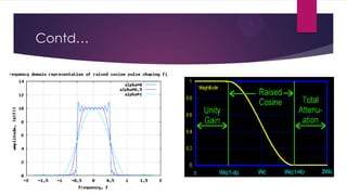
without sharp edges. This filter is the well-known raised cosine filter and its frequency response is given by
H(w)= τ…………………………….0≤w≤c
τ{cos2[τ(w-c)/4α]}…………c≤w≤d
0…………………………….w>d
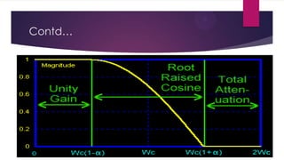
where w is the radian frequency 2πf, τ is the pulse period, α is roll off factor, c is equal to π(1-α)/τ , d is equal to
π(1+α)/τ.](https://image.slidesharecdn.com/pulseshapingfirfilterforwcdma-140216134232-phpapp02/85/Pulse-Shaping-FIR-Filter-for-WCDMA-11-320.jpg)
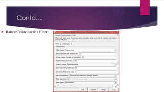
![Square Root Raised Cosine Filter
The frequency Response of the Square-Root Raised Cosine is given as below.
H(w)=√τ…………………………….0≤w≤c
√τ{cos[τ(w-c)/4α]}…………c≤w≤d
0…………………………….w>d
The consequence of pulse shaping is that it distorts the shape of the original time domain rectangular pulse into a
smoothly rounded pulse with damped oscillations (ripples) before and after the ½ To points. The ripples result from
the convolution of the rectangular pulse with the raised cosine impulse response (convolution is the process of
filtering in the time domain). Reduced bandwidth means larger ripple, which exacerbates ISI and increases the
likelihood of an incorrect decision (that is, error) at the receiver.](https://image.slidesharecdn.com/pulseshapingfirfilterforwcdma-140216134232-phpapp02/85/Pulse-Shaping-FIR-Filter-for-WCDMA-13-320.jpg)
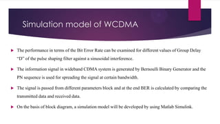
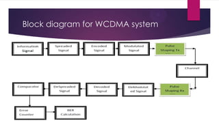


This document analyzes the simulation parameters of a pulse shaping FIR filter for WCDMA. It simulates a square root raised cosine pulse shaping filter in MATLAB Simulink with varying group delay parameters. The simulation measures the number of bits, number of errors, and bit error rate at different group delays. It finds that the bit error rate is minimized at a group delay of 6 symbol periods. The optimal values found are a group delay of 6 and a roll off factor of 0.22.


![Multiband Transceivers - [Chapter 4] Design Parameters of Wireless Radios](https://cdn.slidesharecdn.com/ss_thumbnails/ch4-150613070934-lva1-app6892-thumbnail.jpg?width=640&height=640&fit=bounds)