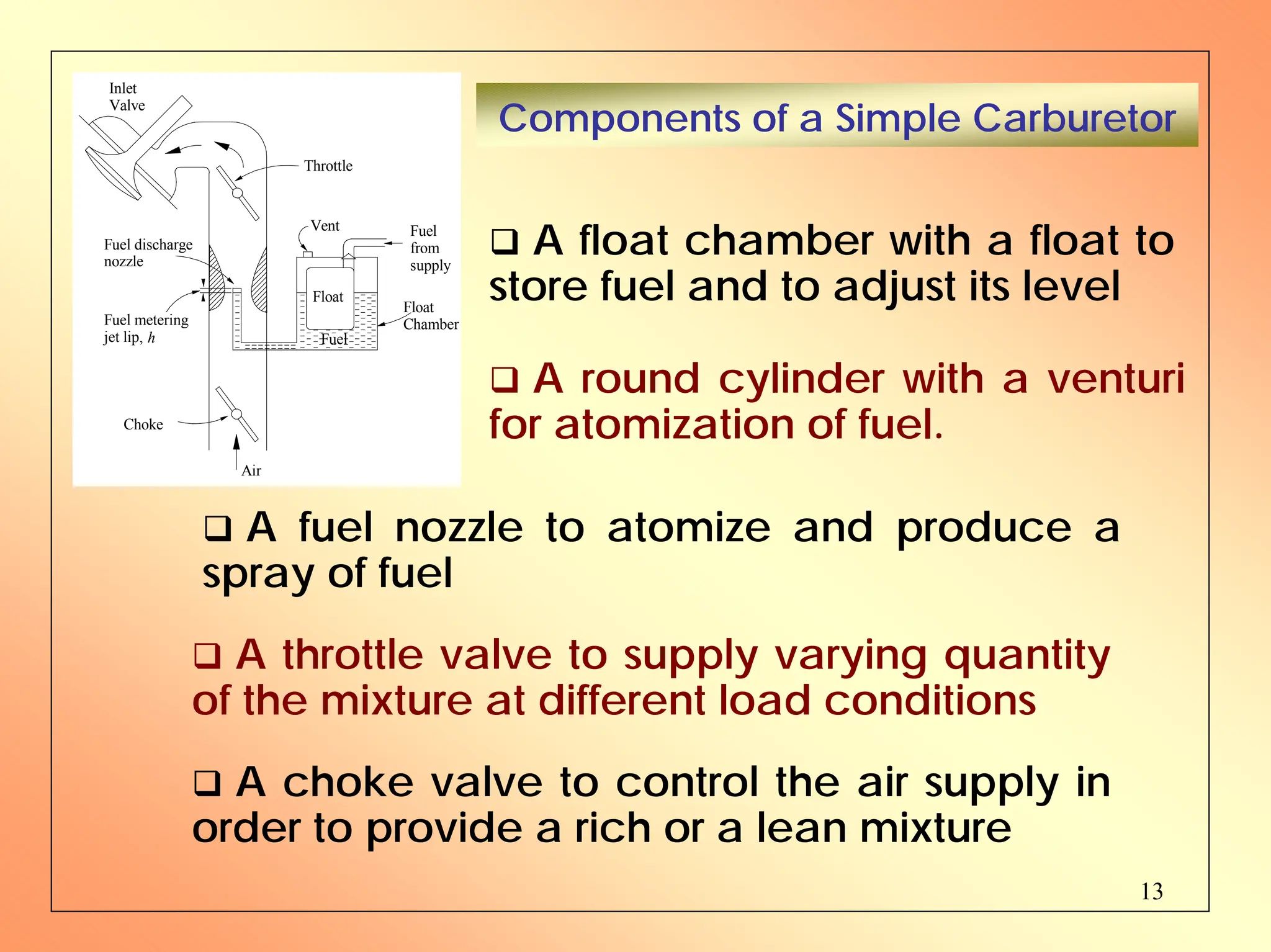
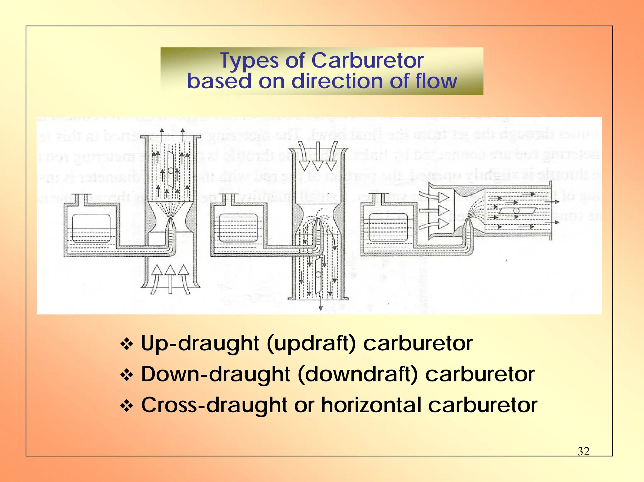
1. The document discusses internal combustion engines and carburetion. It describes the basic components and functions of a carburetor, including the float chamber, venturi, fuel nozzle, choke, and throttle.
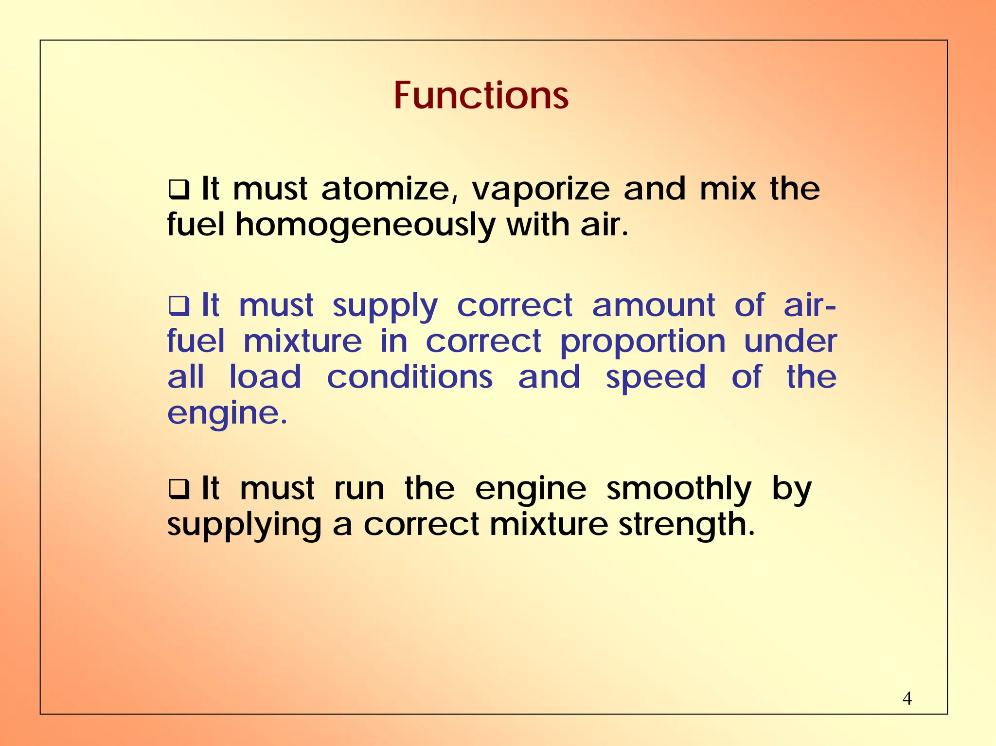
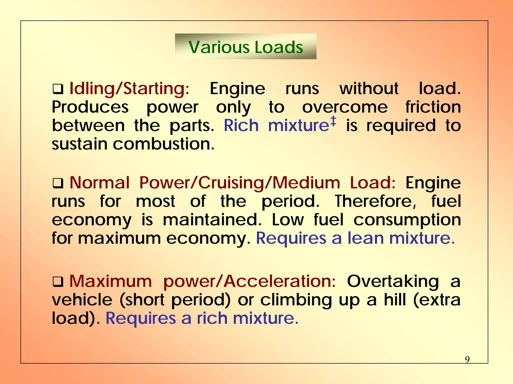
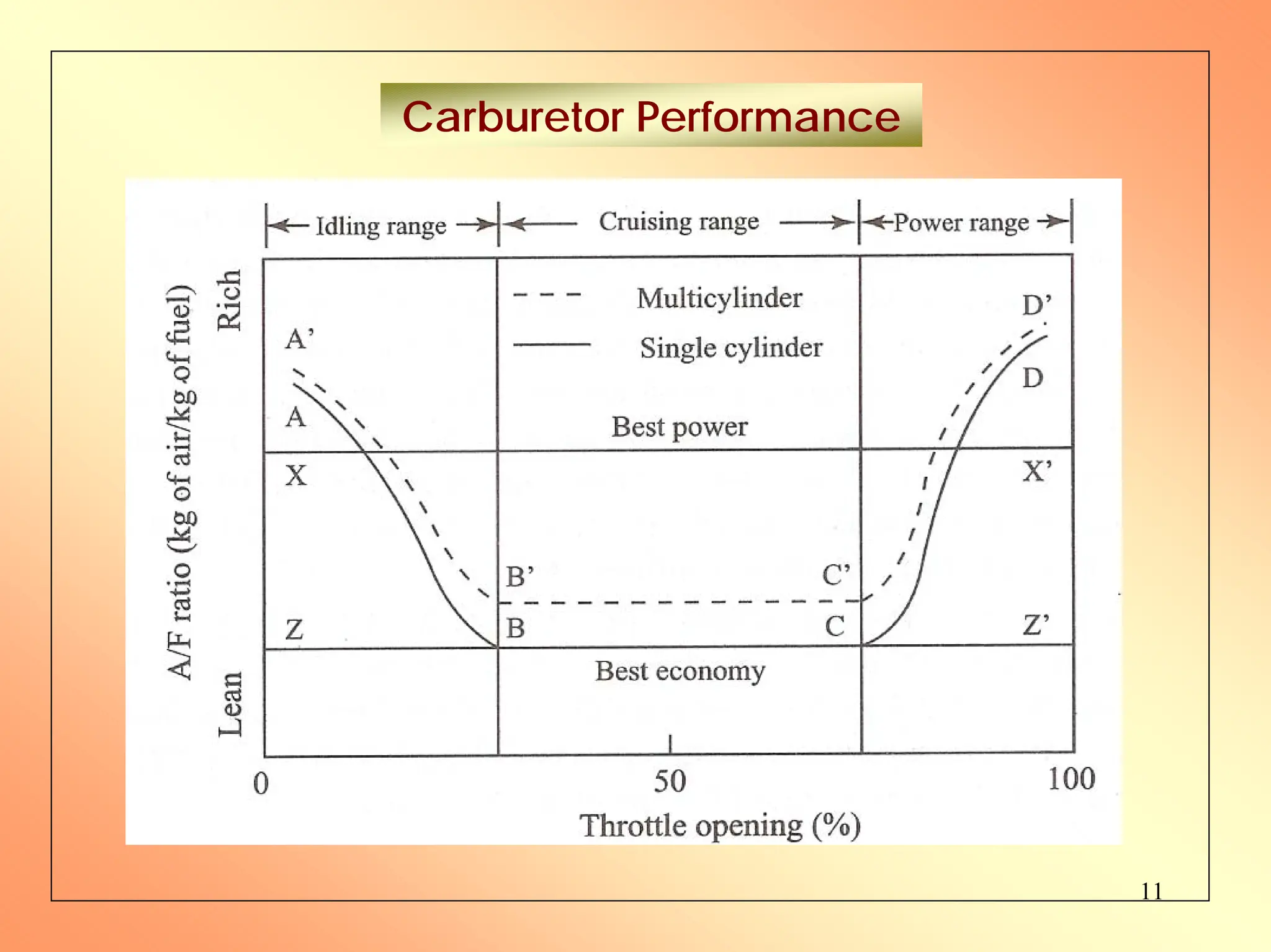
2. It explains factors that affect carburetion like fuel quality, temperature, and engine speed. It also discusses air-fuel mixtures for different engine loads and the need for rich mixtures during idling/starting and acceleration.
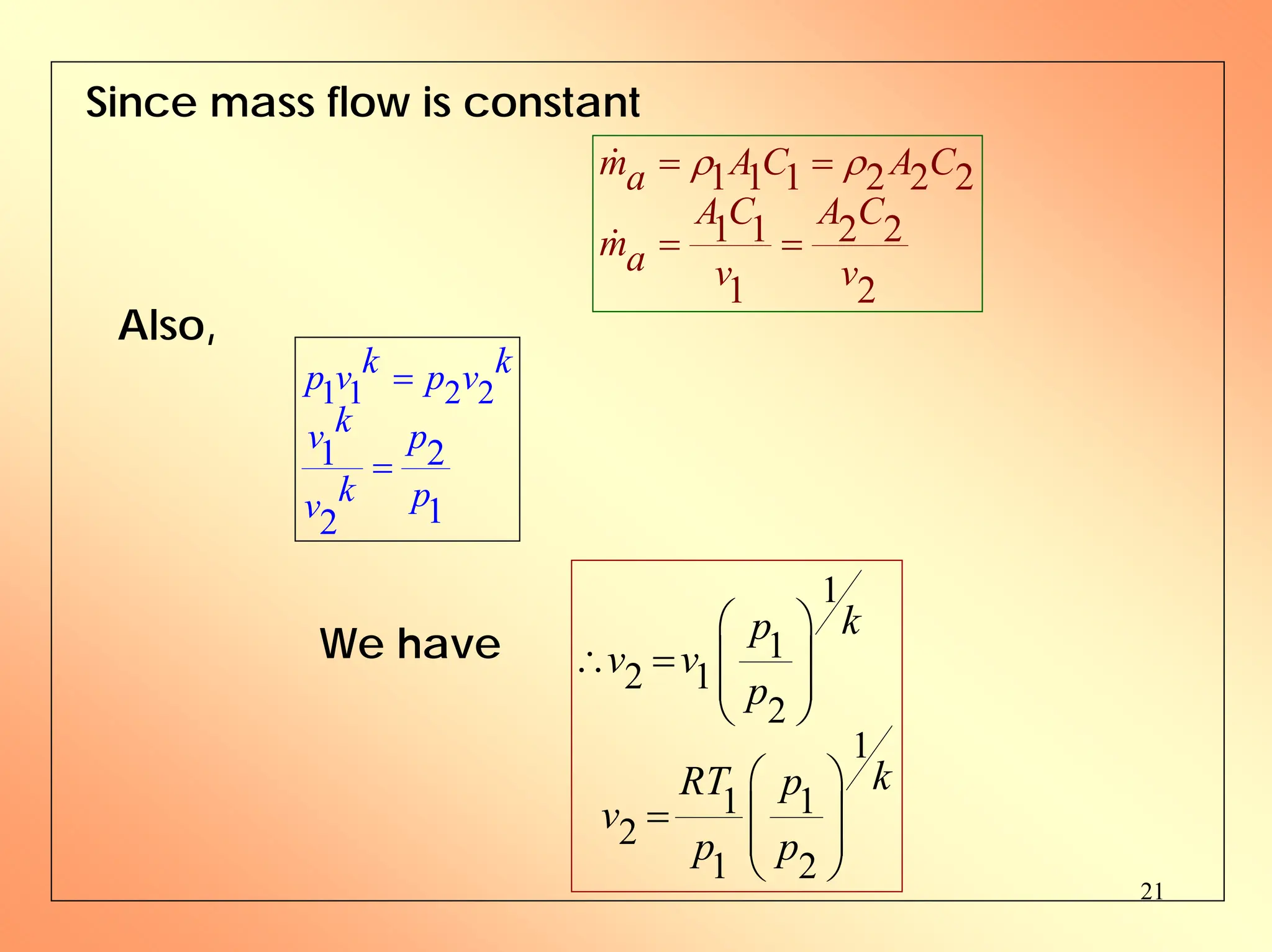
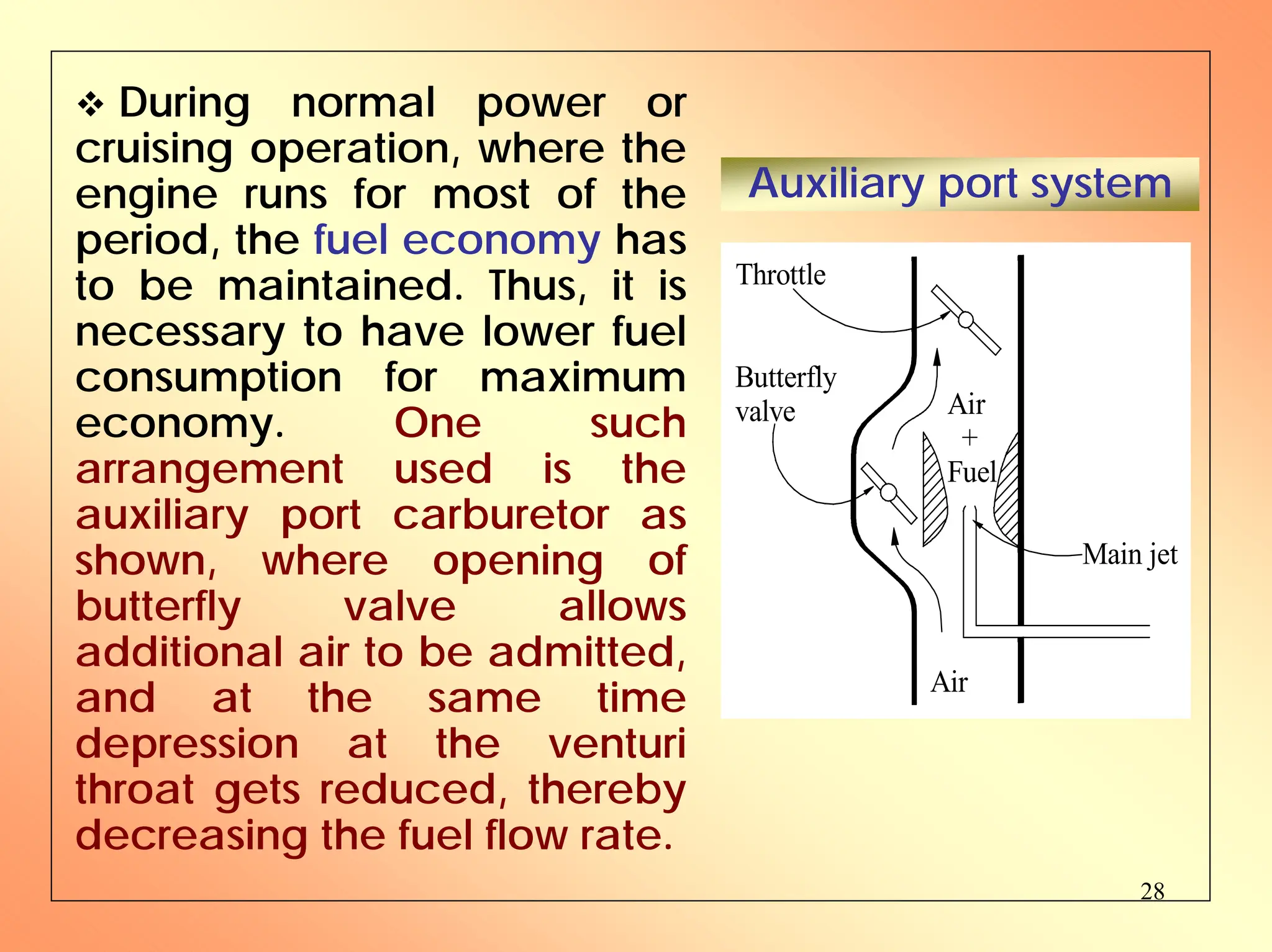
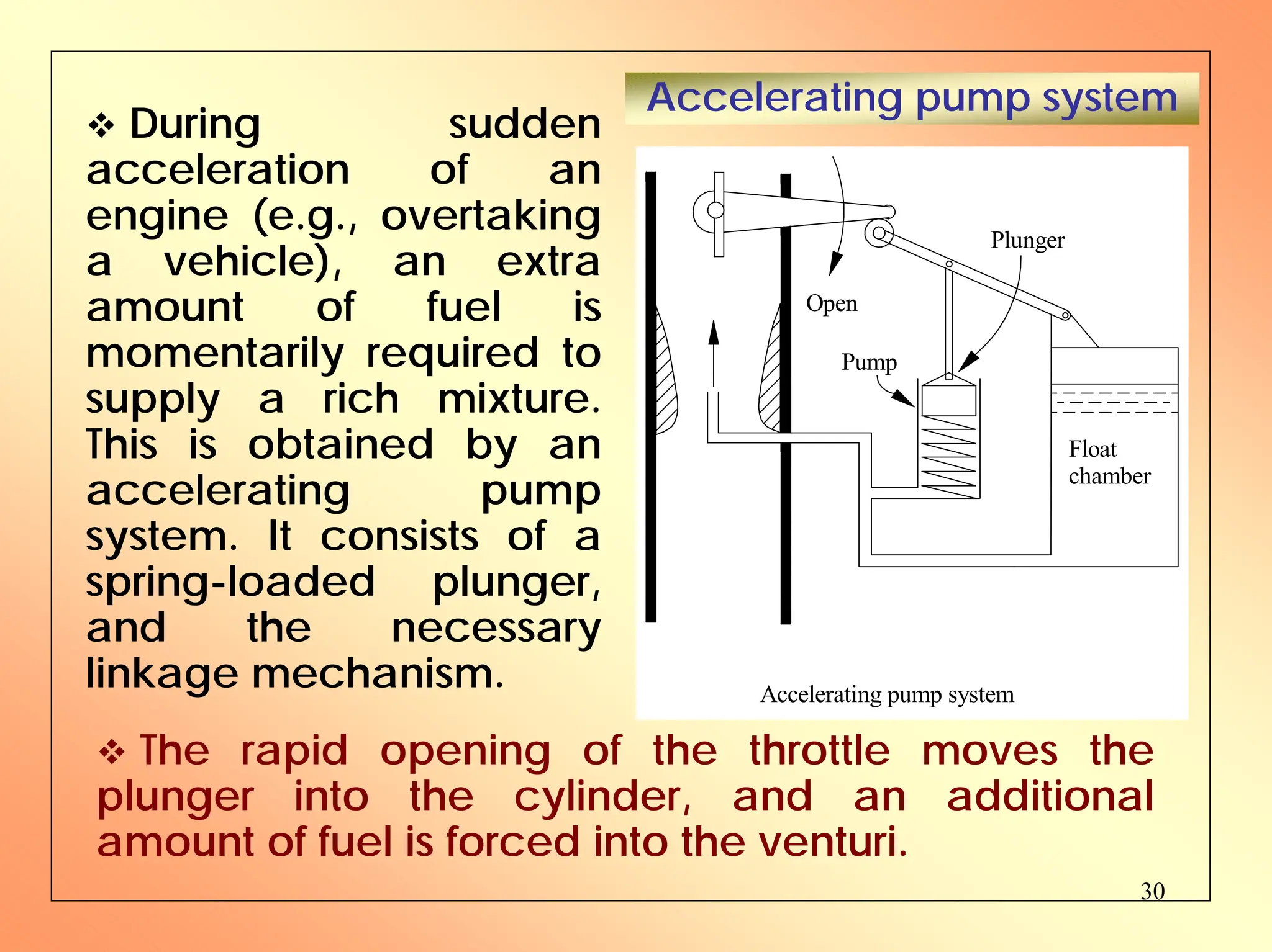
3. The document provides details on the design and operation of simple and advanced carburetors. It describes systems added to basic carburetors like idling, auxiliary ports, power enrichment, and accelerating pumps to provide the proper air-fuel mixture under varying operating