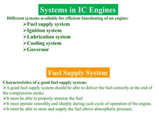
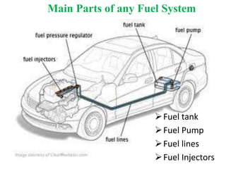
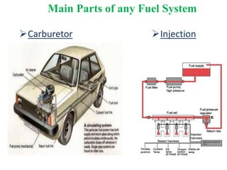
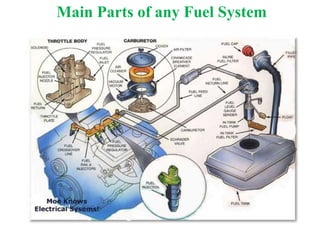
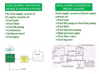
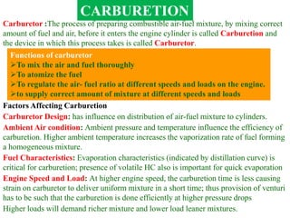
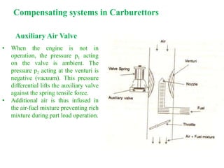
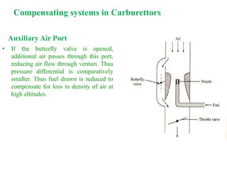
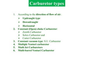
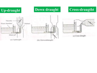
IC Engines
Fuel Supply Systems
Systems in IC Engines
Different systems available for efficient functioning of an engine:
Fuel supply system
Ignition system
Lubrication system
Cooling system
Governor
Fuel Supply System
Characteristics of a good fuel supply system:
A good fuel supply system should be able to deliver the fuel correctly at the end of
the compression stroke.
It must be able to properly atomize the fuel.
It must operate smoothly and sharply during each cycle of operation of the engine.
It must be able to store and supply the fuel above atmospheric pressure.
Fuel tank
Fuel Pump
Fuel lines
Fuel Injectors
Main Parts of any Fuel System
Carburetor Injection
Main Parts of any Fuel System
Fuel Heating value,
QR (J/kg)
Gasoline 43 x 106
Methane 50 x 106
Methanol 20 x 106
Ethanol 27 x 106
Coal 34 x 106
Paper 17 x 106
Fruit Loops 16 x 106
Hydrogen 120 x 106
U235 fission 82,000,000 x 106
S. No Name of fuel Calorific value, kcal/kg
1 Light Diesel Oil (L.D.O) 10300
2 High speed diesel oil (HSD) 10550
3 Power kerosene 10850
4 Petrol 11100
FUEL SUPPLY SYSTEM IN
SPARK IGNITION ENGINE
FUEL SUPPLY SYSTEM IN
DIESEL ENGINE
The fuel supply system of
SI engine consists of:
Fuel tank
Fuel Filter
Fuel lift pump
Carburetor
Sediment bowl
Fuel pipes
Fuel supply system of diesel engine
consists of:
Fuel tank
Fuel lift pump or fuel feed pump
Fuel filter
Fuel injection pump
High pressure pipe
Over flow valve
Fuel injector
CARBURETION
Carburetor :The process of preparing combustible air-fuel mixture, by mixing correct
amount of fuel and air, before it enters the engine cylinder is called Carburetion and
the device in which this process takes is called Carburetor.
Functions of carburetor
To mix the air and fuel thoroughly
To atomize the fuel
To regulate the air- fuel ratio at different speeds and loads on the engine.
to supply correct amount of mixture at different speeds and loads
Factors Affecting Carburetion
Carburetor Design: has influence on distribution of air-fuel mixture to cylinders.
Ambient Air condition: Ambient pressure and temperature influence the efficiency of
carburetion. Higher ambient temperature increases the vaporization rate of fuel forming
a homogeneous mixture.
Fuel Characteristics: Evaporation characteristics (indicated by distillation curve) is
critical for carburetion; presence of volatile HC also is important for quick evaporation
Engine Speed and Load: At higher engine speed, the carburetion time is less causing
strain on carburetor to deliver uniform mixture in a short time; thus provision of venturi
has to be such that the carburetion is done efficiently at higher pressure drops
Higher loads will demand richer mixture and lower load leaner mixtures.
Chemically Correct Mixture: Stoichiometric or balanced chemical mixture in
which air is provided to completely burn the fuel; the excess air factor is unity
Rich Mixture: Fuel is in excess of what is required to burn the fuel completely.
Lean Mixture: Air is in excess of what is required to burn the fuel completely.
Range of Air-Fuel Ratio for Gasoline in SI Engines:
9:1 (rich) to 19:1(lean)
The stoichiometric value for gasoline is 14:1
The SI engine will not run for too rich or too lean mixtures.
Types of Air-Fuel Mixtures
The air-fuel ratio affects the power output and brake specific fuel consumption of
the engine as shown in the Figure.
The mixture corresponding to maximum output on the curve is called best
power A/F mixture, which is richer than the stoichiometric mixture.
Best power air fuel ratio is 12:1
The mixture corresponding to maximum BSFC on the curve is called best
economy A/F mixture, which is leaner than the stoichiometric mixture.
Best economy air fuel ratio is 16:1
Mixture Requirements
at Different Engine Conditions
The actual A/F ratio
requirement for an automotive
carburetor falls in 3 ranges:
Idling (rich)
Cruising (lean)
High Power (rich)
Idling Range (1-2): During idling, engine
operates at no load and closed throttle.
The engine requires rich mixture for starting at
idling.
Rich mixture is required to compensate for the
charge dilution due to exhaust gases from the
combustion chamber.
Also, the amount of fresh charge admitted is
less due to smaller throttle opening.
Exhaust gas dilution prevents efficient
combustion by reducing the contact between
the fuel and air particles.
Rich mixture improves the contact of fuel and
air by providing efficient combustion at idling
conditions.
As the throttle is opened further, the exhaust
gas dilution reduces and the mixture
requirement shifts to the leaner side.
Cruising Range (2-3
Focus is on fuel economy.
No exhaust gas dilution.
Carburetor has to give best economy mixture
i.e.. Lean mixture.
Mixture Requirements
at Different Engine Conditions
High Power Range (3-4)
As high power is required, additional fuel has
to be supplied to achieve rich mixture in this
range.
Rich mixture also prevents overheating by
reducing the flame temperature and cylinder
temperature.
Principle of Operation of Simple Carburettor
A simple carburetor consists of
Fuel Strainer
 A float chamber,
Fuel discharge nozzle,
A metering orifice,
A venturi
A throttle valve and
Choke.
Fuel movement inside Carburetor
Fuel strainer is used to trap debris from the fuel and prevent choking of the
fuel nozzle. It is removed periodically for cleaning.
( If the amount of fuel in the
float chamber falls below the
designed level, the float goes
down, thereby opening the fuel
supply valve and admitting
fuel. When the designed level
has been reached, the float
closes the fuel supply valve
thus stopping the additional
fuel.)
The float chamber is vented to the atmosphere.
Fuel is fed to the fuel discharge jet, the tip of which is located at the throat of the venturi
Float Chamber: The float and needle valve maintain the fuel level as constant.
In carburetor, the air passing
through the venturi, picks up the
fuel discharged from a discharge
jet/nozzle.
During suction stroke air is
drawn through the venturi.
Venturi accelerates the air
causing a pressure drop.
Venturi: Venturi is a tube of decreasing cross section with a minimum area at
the throat. As the air passes through the venturi, the velocity increases reaching
maximum at the venture throat. Correspondingly the pressure decreases
reaching a minimum.
This pressure drop provides vacuum necessary to meter the air-fuel mixture to the
engine manifold.
Pressure drop is proportional to the throttle opening or load on the engine.
Throttle Valve: Throttle valve achieves governing of SI engine by varying the
A/F ratio. It is a butterfly valve located after the venturi tube. When the load is
less, the throttle is in near closed position and less air-fuel mixture is delivered.
If the load is high, throttle is fully opened and more quantity of air-fuel mixture
is delivered and the power output is high.
Choke: The choke valve is located between the entrance to the carburetor and
venturi throat. It is also of butterfly type.
When choke is partly closed, a large pressure drop occurs at the venturi
throat, which provides a rich mixture by induction of large amount of fuel.
Choke valves are spring loaded to prevent excessive choking and are sometimes
automatically controlled by thermostat.
For providing rich mixture during idling, an idling adjustment is provided. It has an idling
passage and idling port.
Rich mixture is required
during cold starting period,
at low cranking speed (
idiling) and before the
engine warmed up
condition. Then the choke
is operated.
The following compensating systems
are used to achieve this:
Air Bleed Jet
Compensating Jet
Emulsion Tube
Back Suction Control Mechanism
Auxiliary Air Valve
Auxiliary Air Port
Altitude Compensating Device
For part load conditions, the carburetor must supply economic air-fuel ratio
mixture. The main metering system will not satisfy this requirement.
Compensating systems in Carburettors
Air Bleed Jet
• It contains an air bleed to the main
nozzle.
• Air flow through the bleed passage is
restricted by orifice.
• When engine is not operating the bleed
passage is filled with fuel.
• When the engine starts the fuel from the
bleed passage is displaced by air flow
from the orifice.
• The air and fuel form an emulsion at the
tip of the bleed passage.
• This causes faster delivery of fuel due
to low viscosity and fuel discharged
rises.
• Thus uniform mixture ratio is supplied.
Compensating Jet
• The purpose of this is to make the
mixture leaner as the throttle opens
progressively.
• An additional jet called compensating
jet is provided with the main jet.
• This jet is also connected to the fuel
well and the fuel is metered through
compensating orifice.
• As the throttle opening increases the
main jet makes the mixture richer by
adding more fuel.
• The compensating jet makes the
mixture leaner proportionately. The
total mixture will make A/F ratio
constant.
• When the main jet is lean,
compensating jet is rich.
Compensating systems in Carburettors
Emulsion Tube
• It is also known as submerged jet
device.
• Here, the main metering jet is kept at a
level 25 mm below the fuel level in
float chamber.
• The jet is called submerged jet. The jet
is placed in a well that has holes
exposed to atmosphere.
• When the throttle opening increases, the
holes in the well are uncovered causing
additional fuel and air to enter the air-
fuel stream, causing the faster A/F
mixture delivery during part load
operation.
Compensating systems in Carburettors
Back Suction Control Mechanism
• In this device, the top of the fuel
chamber is connected to air entry by
means of a large vent line fitted with a
control valve.
• The second line connects the fuel float
chamber to venturi throat via a metering
orifice.
• When the control valve is opened, the
pressure in float chamber is p1 and the
throat pressure is p2 which is lower than
p1. This causes the fuel to flow. When
the valve is closed, there is no
difference in pressure and hence no fuel
flow.
• Thus the control valve achieves the
desired air fuel ratio during part load
operation.
Compensating systems in Carburettors
Auxiliary Air Valve
• When the engine is not in
operation, the pressure p1 acting
on the valve is ambient. The
pressure p2 acting at the venturi is
negative (vacuum). This pressure
differential lifts the auxiliary valve
against the spring tensile force.
• Additional air is thus infused in
the air-fuel mixture preventing rich
mixture during part load operation.
Compensating systems in Carburettors
Auxiliary Air Port
• If the butterfly valve is opened,
additional air passes through this port,
reducing air flow through venturi. Thus
pressure differential is comparatively
smaller. Thus fuel drawn is reduced to
compensate for loss in density of air at
high altitudes.
Compensating systems in Carburettors
1. According to the direction of flow of air:
 Updraught type
 Downdraught
 Horizontal
2. Constant (Open) choke Carburetor:
 Zenith Carburetor
 Solex Carburetor and
 Carter Carburetor
3. Constant vacuum type: S.U. Carburetor
4. Multiple Venturi carburetor
5. Multi Jet Carburetors
6. Multi-barrel Venturi Carburetor
Carburetor types
Up-draught Down draught Cross-draugtht
Constant Choke Carburetor
In the constant choke carburetor, the air and fuel flow areas are always
maintained to be constant. But the pressure difference or depression
which causes the flow of fuel and air are being varied as per the demand
on the engine.
e.g. Solex and Zenith carburetors
Constant Vacuum Carburetor
In the constant vacuum carburetor, (Sometimes called variable choke
carburetor) air and fuel flow areas are being varied as per the demand
on the engine, while the vacuum is maintained to be always same.
e.g. S.U. and Carter carburetors
Multiple Venturi Carburetor
Multiple venturi system uses double or triple venturi.
The boost venturi is located concentrically within the main venturi,
The discharge edge of the boost venturi is located at the throat of the main
venture.
 The boost venturi is positioned upstream of the throat of the larger main
venturi.
Only a fraction of the total air
flows though the boost venturi.
Now the pressure at the boost
venture exit equals the pressure
at the main venturi throat.
 The fuel nozzle is located at
the throat of the boost venturi.
This arrangement results in the following:
High depression is created in the region of the fuel nozzle. Hence, better
control over the fuel flow and improved atomization are possible. At the boost
venture throat, velocity of air is a high as 200 m/s.
An annular blanket of air is formed. This blanket keeps the fuel (droplets of
fuel) off the alls of the induction tract.
Excellent low speed full throttle
operation is possible.
More efficient mixing of the air
and fuel is obtained without
incurring an acceptable reduction
in volumetric efficiency.
Volumetric efficiency reduces
only slightly since only the
portion of the incoming air is
subjected to the increased
pressure drop.
Multi Jet Carburetors
A single barrel carburetor has only one barrel, whereas a duel carburetor has
two barrel. Each of these two barrels in a duel carburetor contains a fuel jet, a
venture tube, and idling system, a choke and a throttle. The float chamber and
the accelerating pump are common to both the barrels.
Multi-barrel Venturi Carburetor
Most of the automotive engines are fitted with single barrel carburetors. A single barrel
carburetor has one outlet connected to the intake manifold of the engine. This type of
carburetor is used extensively on engine of six less number of cylinders.
Carburetor with tow outlets connected to two intake manifolds are known as two
barrel or tow throat carburetors
FUEL PUMPS
Mechanical (Petrol) Pump
Electric Pump
Electric Pump
Mechanical (Petrol) Pump
Gasoline Injection System
Some of the recent automotive engines are equipped with gasoline injection
system, instead of carburetion for one or more of the following reasons:
To have uniform distribution of fuel in a multi cylinder engine
To improve breathing capacity i.e., volumetric efficiency.
To reduce or eliminate detonation
To prevent fuel loss during scavenging in case of two-stroke engines.
The fuel injection system can be classified as:
Gasoline direct injection into the cylinder (GDI)
Port injection
Timed, and (b) Continuous
Multi Point Injection
Port Injection and (b) Throttle body injection
Types of Injection Systems
Gasoline Direct Injection
Major Objectives Of The GDI Engine
• Ultra-low fuel consumption, which betters that of diesel engines.
• Superior power to conventional MPI engines
PORT INJECTION or
MULTI POINT INJECTION
THROTTLE BODY INJECTION SYSTEM
( SINGLE POINT INJECTION)
MULTI-POINT FUEL INJECTION
(MPFI) SYSTEM
The main purpose of the Multi-Point Fuel
Injection (MPFI) system is to supply a
proper ratio of gasoline and air to the
cylinders. These systems function under
two basic arrangements, namely
Port injection
Throttle body injection
Thank you

IC Engines Fuel Systems PRINCIPLE AND WORKING

  • 1.
  • 2.
    Systems in ICEngines Different systems available for efficient functioning of an engine: Fuel supply system Ignition system Lubrication system Cooling system Governor Fuel Supply System Characteristics of a good fuel supply system: A good fuel supply system should be able to deliver the fuel correctly at the end of the compression stroke. It must be able to properly atomize the fuel. It must operate smoothly and sharply during each cycle of operation of the engine. It must be able to store and supply the fuel above atmospheric pressure.
  • 3.
    Fuel tank Fuel Pump Fuellines Fuel Injectors Main Parts of any Fuel System
  • 4.
  • 5.
    Main Parts ofany Fuel System
  • 6.
    Fuel Heating value, QR(J/kg) Gasoline 43 x 106 Methane 50 x 106 Methanol 20 x 106 Ethanol 27 x 106 Coal 34 x 106 Paper 17 x 106 Fruit Loops 16 x 106 Hydrogen 120 x 106 U235 fission 82,000,000 x 106 S. No Name of fuel Calorific value, kcal/kg 1 Light Diesel Oil (L.D.O) 10300 2 High speed diesel oil (HSD) 10550 3 Power kerosene 10850 4 Petrol 11100
  • 7.
    FUEL SUPPLY SYSTEMIN SPARK IGNITION ENGINE FUEL SUPPLY SYSTEM IN DIESEL ENGINE The fuel supply system of SI engine consists of: Fuel tank Fuel Filter Fuel lift pump Carburetor Sediment bowl Fuel pipes Fuel supply system of diesel engine consists of: Fuel tank Fuel lift pump or fuel feed pump Fuel filter Fuel injection pump High pressure pipe Over flow valve Fuel injector
  • 8.
    CARBURETION Carburetor :The processof preparing combustible air-fuel mixture, by mixing correct amount of fuel and air, before it enters the engine cylinder is called Carburetion and the device in which this process takes is called Carburetor. Functions of carburetor To mix the air and fuel thoroughly To atomize the fuel To regulate the air- fuel ratio at different speeds and loads on the engine. to supply correct amount of mixture at different speeds and loads Factors Affecting Carburetion Carburetor Design: has influence on distribution of air-fuel mixture to cylinders. Ambient Air condition: Ambient pressure and temperature influence the efficiency of carburetion. Higher ambient temperature increases the vaporization rate of fuel forming a homogeneous mixture. Fuel Characteristics: Evaporation characteristics (indicated by distillation curve) is critical for carburetion; presence of volatile HC also is important for quick evaporation Engine Speed and Load: At higher engine speed, the carburetion time is less causing strain on carburetor to deliver uniform mixture in a short time; thus provision of venturi has to be such that the carburetion is done efficiently at higher pressure drops Higher loads will demand richer mixture and lower load leaner mixtures.
  • 9.
    Chemically Correct Mixture:Stoichiometric or balanced chemical mixture in which air is provided to completely burn the fuel; the excess air factor is unity Rich Mixture: Fuel is in excess of what is required to burn the fuel completely. Lean Mixture: Air is in excess of what is required to burn the fuel completely. Range of Air-Fuel Ratio for Gasoline in SI Engines: 9:1 (rich) to 19:1(lean) The stoichiometric value for gasoline is 14:1 The SI engine will not run for too rich or too lean mixtures. Types of Air-Fuel Mixtures
  • 10.
    The air-fuel ratioaffects the power output and brake specific fuel consumption of the engine as shown in the Figure. The mixture corresponding to maximum output on the curve is called best power A/F mixture, which is richer than the stoichiometric mixture. Best power air fuel ratio is 12:1 The mixture corresponding to maximum BSFC on the curve is called best economy A/F mixture, which is leaner than the stoichiometric mixture. Best economy air fuel ratio is 16:1 Mixture Requirements at Different Engine Conditions The actual A/F ratio requirement for an automotive carburetor falls in 3 ranges: Idling (rich) Cruising (lean) High Power (rich)
  • 11.
    Idling Range (1-2):During idling, engine operates at no load and closed throttle. The engine requires rich mixture for starting at idling. Rich mixture is required to compensate for the charge dilution due to exhaust gases from the combustion chamber. Also, the amount of fresh charge admitted is less due to smaller throttle opening. Exhaust gas dilution prevents efficient combustion by reducing the contact between the fuel and air particles. Rich mixture improves the contact of fuel and air by providing efficient combustion at idling conditions. As the throttle is opened further, the exhaust gas dilution reduces and the mixture requirement shifts to the leaner side. Cruising Range (2-3 Focus is on fuel economy. No exhaust gas dilution. Carburetor has to give best economy mixture i.e.. Lean mixture. Mixture Requirements at Different Engine Conditions High Power Range (3-4) As high power is required, additional fuel has to be supplied to achieve rich mixture in this range. Rich mixture also prevents overheating by reducing the flame temperature and cylinder temperature.
  • 12.
    Principle of Operationof Simple Carburettor A simple carburetor consists of Fuel Strainer  A float chamber, Fuel discharge nozzle, A metering orifice, A venturi A throttle valve and Choke.
  • 15.
  • 16.
    Fuel strainer isused to trap debris from the fuel and prevent choking of the fuel nozzle. It is removed periodically for cleaning. ( If the amount of fuel in the float chamber falls below the designed level, the float goes down, thereby opening the fuel supply valve and admitting fuel. When the designed level has been reached, the float closes the fuel supply valve thus stopping the additional fuel.) The float chamber is vented to the atmosphere. Fuel is fed to the fuel discharge jet, the tip of which is located at the throat of the venturi Float Chamber: The float and needle valve maintain the fuel level as constant.
  • 17.
    In carburetor, theair passing through the venturi, picks up the fuel discharged from a discharge jet/nozzle. During suction stroke air is drawn through the venturi. Venturi accelerates the air causing a pressure drop. Venturi: Venturi is a tube of decreasing cross section with a minimum area at the throat. As the air passes through the venturi, the velocity increases reaching maximum at the venture throat. Correspondingly the pressure decreases reaching a minimum. This pressure drop provides vacuum necessary to meter the air-fuel mixture to the engine manifold. Pressure drop is proportional to the throttle opening or load on the engine.
  • 18.
    Throttle Valve: Throttlevalve achieves governing of SI engine by varying the A/F ratio. It is a butterfly valve located after the venturi tube. When the load is less, the throttle is in near closed position and less air-fuel mixture is delivered. If the load is high, throttle is fully opened and more quantity of air-fuel mixture is delivered and the power output is high.
  • 19.
    Choke: The chokevalve is located between the entrance to the carburetor and venturi throat. It is also of butterfly type. When choke is partly closed, a large pressure drop occurs at the venturi throat, which provides a rich mixture by induction of large amount of fuel. Choke valves are spring loaded to prevent excessive choking and are sometimes automatically controlled by thermostat. For providing rich mixture during idling, an idling adjustment is provided. It has an idling passage and idling port. Rich mixture is required during cold starting period, at low cranking speed ( idiling) and before the engine warmed up condition. Then the choke is operated.
  • 20.
    The following compensatingsystems are used to achieve this: Air Bleed Jet Compensating Jet Emulsion Tube Back Suction Control Mechanism Auxiliary Air Valve Auxiliary Air Port Altitude Compensating Device For part load conditions, the carburetor must supply economic air-fuel ratio mixture. The main metering system will not satisfy this requirement. Compensating systems in Carburettors
  • 21.
    Compensating systems inCarburettors Air Bleed Jet • It contains an air bleed to the main nozzle. • Air flow through the bleed passage is restricted by orifice. • When engine is not operating the bleed passage is filled with fuel. • When the engine starts the fuel from the bleed passage is displaced by air flow from the orifice. • The air and fuel form an emulsion at the tip of the bleed passage. • This causes faster delivery of fuel due to low viscosity and fuel discharged rises. • Thus uniform mixture ratio is supplied.
  • 22.
    Compensating Jet • Thepurpose of this is to make the mixture leaner as the throttle opens progressively. • An additional jet called compensating jet is provided with the main jet. • This jet is also connected to the fuel well and the fuel is metered through compensating orifice. • As the throttle opening increases the main jet makes the mixture richer by adding more fuel. • The compensating jet makes the mixture leaner proportionately. The total mixture will make A/F ratio constant. • When the main jet is lean, compensating jet is rich. Compensating systems in Carburettors
  • 23.
    Emulsion Tube • Itis also known as submerged jet device. • Here, the main metering jet is kept at a level 25 mm below the fuel level in float chamber. • The jet is called submerged jet. The jet is placed in a well that has holes exposed to atmosphere. • When the throttle opening increases, the holes in the well are uncovered causing additional fuel and air to enter the air- fuel stream, causing the faster A/F mixture delivery during part load operation. Compensating systems in Carburettors
  • 24.
    Back Suction ControlMechanism • In this device, the top of the fuel chamber is connected to air entry by means of a large vent line fitted with a control valve. • The second line connects the fuel float chamber to venturi throat via a metering orifice. • When the control valve is opened, the pressure in float chamber is p1 and the throat pressure is p2 which is lower than p1. This causes the fuel to flow. When the valve is closed, there is no difference in pressure and hence no fuel flow. • Thus the control valve achieves the desired air fuel ratio during part load operation. Compensating systems in Carburettors
  • 25.
    Auxiliary Air Valve •When the engine is not in operation, the pressure p1 acting on the valve is ambient. The pressure p2 acting at the venturi is negative (vacuum). This pressure differential lifts the auxiliary valve against the spring tensile force. • Additional air is thus infused in the air-fuel mixture preventing rich mixture during part load operation. Compensating systems in Carburettors
  • 26.
    Auxiliary Air Port •If the butterfly valve is opened, additional air passes through this port, reducing air flow through venturi. Thus pressure differential is comparatively smaller. Thus fuel drawn is reduced to compensate for loss in density of air at high altitudes. Compensating systems in Carburettors
  • 27.
    1. According tothe direction of flow of air:  Updraught type  Downdraught  Horizontal 2. Constant (Open) choke Carburetor:  Zenith Carburetor  Solex Carburetor and  Carter Carburetor 3. Constant vacuum type: S.U. Carburetor 4. Multiple Venturi carburetor 5. Multi Jet Carburetors 6. Multi-barrel Venturi Carburetor Carburetor types
  • 28.
  • 29.
    Constant Choke Carburetor Inthe constant choke carburetor, the air and fuel flow areas are always maintained to be constant. But the pressure difference or depression which causes the flow of fuel and air are being varied as per the demand on the engine. e.g. Solex and Zenith carburetors Constant Vacuum Carburetor In the constant vacuum carburetor, (Sometimes called variable choke carburetor) air and fuel flow areas are being varied as per the demand on the engine, while the vacuum is maintained to be always same. e.g. S.U. and Carter carburetors
  • 30.
    Multiple Venturi Carburetor Multipleventuri system uses double or triple venturi. The boost venturi is located concentrically within the main venturi, The discharge edge of the boost venturi is located at the throat of the main venture.  The boost venturi is positioned upstream of the throat of the larger main venturi. Only a fraction of the total air flows though the boost venturi. Now the pressure at the boost venture exit equals the pressure at the main venturi throat.  The fuel nozzle is located at the throat of the boost venturi.
  • 31.
    This arrangement resultsin the following: High depression is created in the region of the fuel nozzle. Hence, better control over the fuel flow and improved atomization are possible. At the boost venture throat, velocity of air is a high as 200 m/s. An annular blanket of air is formed. This blanket keeps the fuel (droplets of fuel) off the alls of the induction tract. Excellent low speed full throttle operation is possible. More efficient mixing of the air and fuel is obtained without incurring an acceptable reduction in volumetric efficiency. Volumetric efficiency reduces only slightly since only the portion of the incoming air is subjected to the increased pressure drop.
  • 32.
    Multi Jet Carburetors Asingle barrel carburetor has only one barrel, whereas a duel carburetor has two barrel. Each of these two barrels in a duel carburetor contains a fuel jet, a venture tube, and idling system, a choke and a throttle. The float chamber and the accelerating pump are common to both the barrels. Multi-barrel Venturi Carburetor Most of the automotive engines are fitted with single barrel carburetors. A single barrel carburetor has one outlet connected to the intake manifold of the engine. This type of carburetor is used extensively on engine of six less number of cylinders. Carburetor with tow outlets connected to two intake manifolds are known as two barrel or tow throat carburetors
  • 33.
  • 34.
  • 35.
  • 36.
    Gasoline Injection System Someof the recent automotive engines are equipped with gasoline injection system, instead of carburetion for one or more of the following reasons: To have uniform distribution of fuel in a multi cylinder engine To improve breathing capacity i.e., volumetric efficiency. To reduce or eliminate detonation To prevent fuel loss during scavenging in case of two-stroke engines.
  • 38.
    The fuel injectionsystem can be classified as: Gasoline direct injection into the cylinder (GDI) Port injection Timed, and (b) Continuous Multi Point Injection Port Injection and (b) Throttle body injection Types of Injection Systems
  • 39.
    Gasoline Direct Injection MajorObjectives Of The GDI Engine • Ultra-low fuel consumption, which betters that of diesel engines. • Superior power to conventional MPI engines
  • 40.
    PORT INJECTION or MULTIPOINT INJECTION THROTTLE BODY INJECTION SYSTEM ( SINGLE POINT INJECTION) MULTI-POINT FUEL INJECTION (MPFI) SYSTEM The main purpose of the Multi-Point Fuel Injection (MPFI) system is to supply a proper ratio of gasoline and air to the cylinders. These systems function under two basic arrangements, namely Port injection Throttle body injection
  • 41.