Downloaded 10,974 times


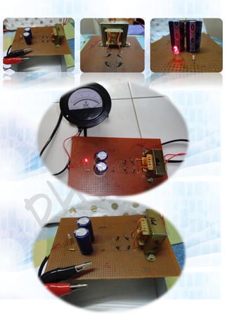
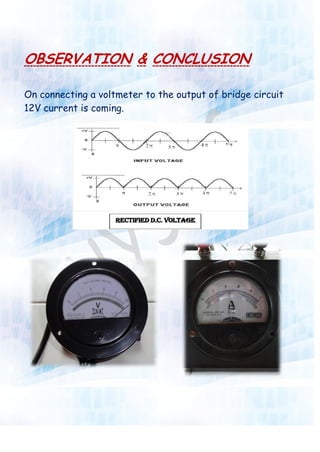


This document describes a student's physics investigatory project to construct a full wave bridge rectifier. The aim is to show that an alternating current (AC) is rectified into a direct current (DC). The materials, circuit diagram, procedure, and working of the rectifier are explained. When tested, the rectifier output 12V of direct current, demonstrating that the AC input was successfully rectified. Common uses of rectifiers are also listed.