The document discusses cable ampacity calculations to determine required cable sizes based on project standards and design criteria. It provides tables with ampacity values for different cable types, sizes, and installation methods based on temperature limits. It also includes correction factors to adjust ampacity values based on ambient temperature and conditions like cable grouping. The purpose is to calculate cable sizes that satisfy load requirements while maintaining safe operating temperatures.
![F:Elementscable programscable ampacity calculation IEC.docx Page 2
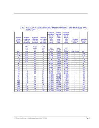
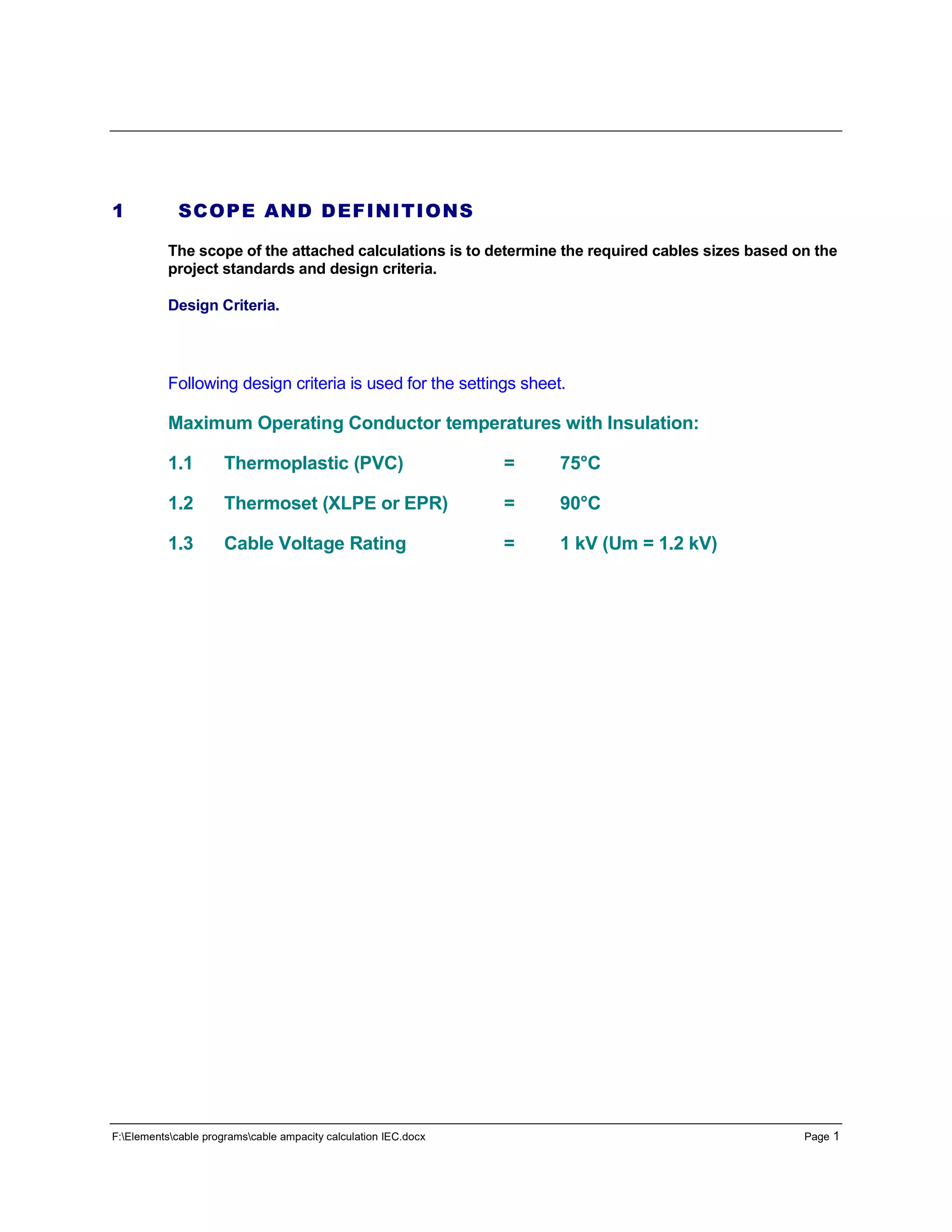
2 CABLE AMPACITY
2.1 Conductor Ampacity Selection
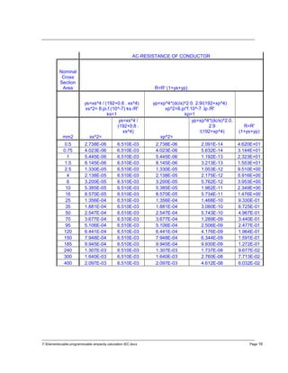
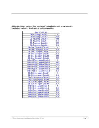
The cable ampacities are based as follows;
PVC insulation, copper conductors –Conductor temperature: 70 °C, reference ambient
temperature: 30 °C
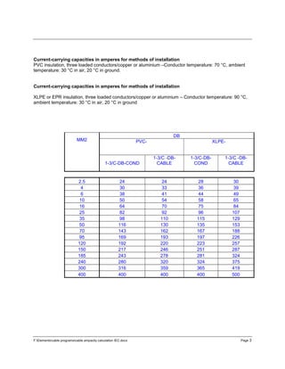
Current-carrying capacities in amperes
for installation methods–XLPE or EPR insulation, copper conductors –Conductor
temperature: 90 °C, reference ambient temperature: 30 °C
MM2
AIR
PVC
XLPE-)
3-1/C
(1.5-16MM2)
&
(25-400MM2)]
1-3/C
3-1/C
(1.5-16MM2)
&
(25-400MM2)]
1-3/C
2.5 25 25 32 32
4 34 34 42 42
6 43 43 54 54
10 60 60 75 75
16 80 80 100 100
25 110 101 135 127
35 137 126 169 158
50 167 153 207 192
70 216 196 268 246
95 264 238 328 298
120 308 276 383 346
150 356 319 444 399
185 409 364 510 456
240 485 430 607 538
300 561 497 703 621
400 600 600 823 823](https://image.slidesharecdn.com/cableampacitycalculations-iec-160611100557/85/Cable-ampacity-calculations-iec-2-320.jpg)
![F:Elementscable programscable ampacity calculation IEC.docx Page 11
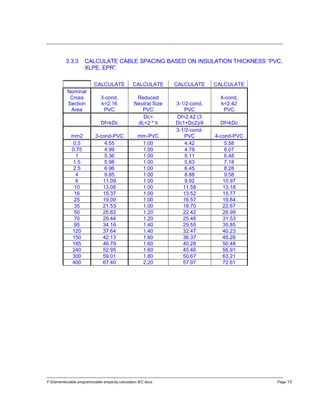
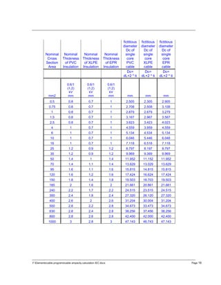
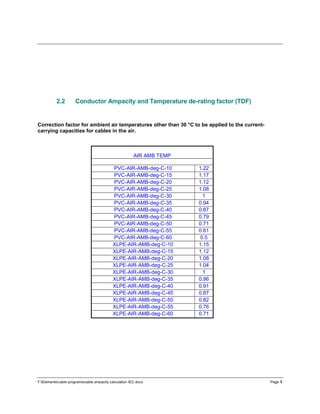
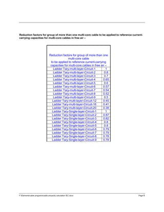
3.3 Resistance of stranded conductors Correction.
3.3.1 DC RESISTANCE @ 70 DEG C OR 90 DEG C
CALCULATE
CALCULATE
STRANDING
FACTOR
CALCULATE CALCULATE
Nominal
Cross
Section
Area
Nominal
CONDUCTOR
Diameter
Minimum
Number
of
Wires in
Conductor
Nominal
Stranded
CONDUCTOR
Diameter
Maximum
Resistance of
Conductor at
20 deg C
Annealed
Copper
Conductor Plain
Wires
Ώ / km
Resistance
at= t Deg C
temperature
IEC-60228-
Annex B
mm2
d=(4/pi*A)^.5
= mm
Circular
Cu
d x str-factor =
Mm
Rdc-t=
[1+0.00393
(t-20)]*
Rdc-20
Ώ/1000
meter =90
0.5 0.798 7 1.134 0.905 36 45.904
0.75 0.977 7 1.134 1.108 24.5 31.240
1 1.128 7 1.134 1.279 18.1 23.079
1.5 1.382 7 1.134 1.567 12.1 15.429
2.5 1.784 7 1.134 2.023 7.41 9.448
4 2.257 7 1.134 2.559 4.61 5.878
6 2.764 7 1.134 3.134 3.08 3.927
10 3.568 7 1.134 4.046 1.83 2.333
16 4.513 7 1.134 5.118 1.15 1.466
25 5.642 7 1.134 6.397 0.727 0.927
35 6.675 7 1.134 7.569 0.524 0.668
50 7.978 19 1.147 9.152 0.387 0.493
70 9.440 19 1.147 10.829 0.268 0.342
95 10.997 19 1.147 12.615 0.193 0.246
120 12.360 37 1.151 14.224 0.153 0.195
150 13.819 37 1.151 15.903 0.124 0.158
185 15.347 37 1.151 17.661 0.0991 0.126
240 17.480 37 1.151 20.115 0.0754 0.096
300 19.543 61 1.152 22.520 0.0601 0.077
400 22.566 61 1.152 26.004 0.047 0.060
500 25.230 61 1.152 29.073 0.0366 0.047
630 28.320 91 1.153 32.656 0.0283 0.036
800 31.913 91 1.153 36.800 0.0221 0.028
1000 35.680 91 1.153 41.143 0.0176 0.022](https://image.slidesharecdn.com/cableampacitycalculations-iec-160611100557/85/Cable-ampacity-calculations-iec-11-320.jpg)