This technical presentation provides an overview of float cum boost battery chargers used for standby applications. It discusses:
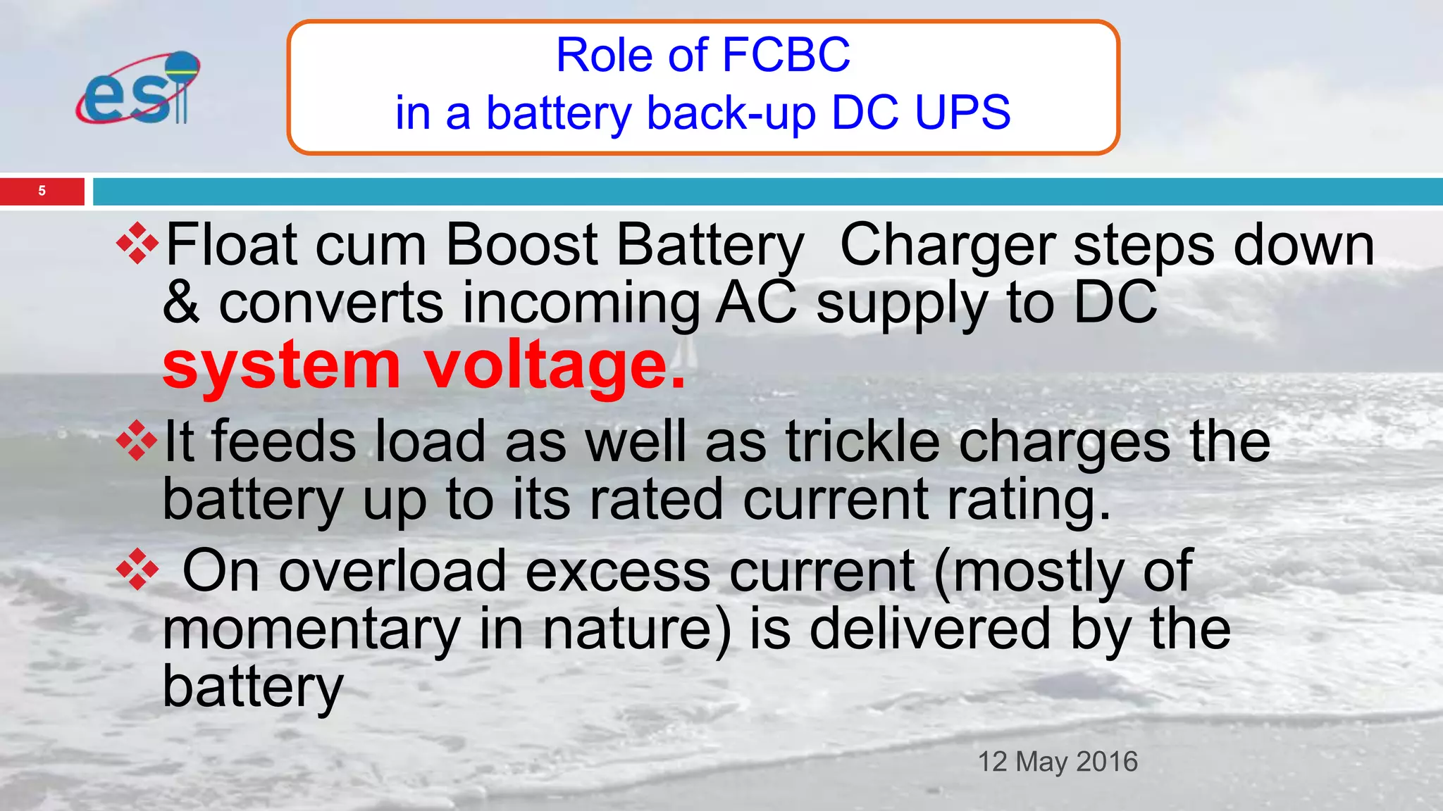
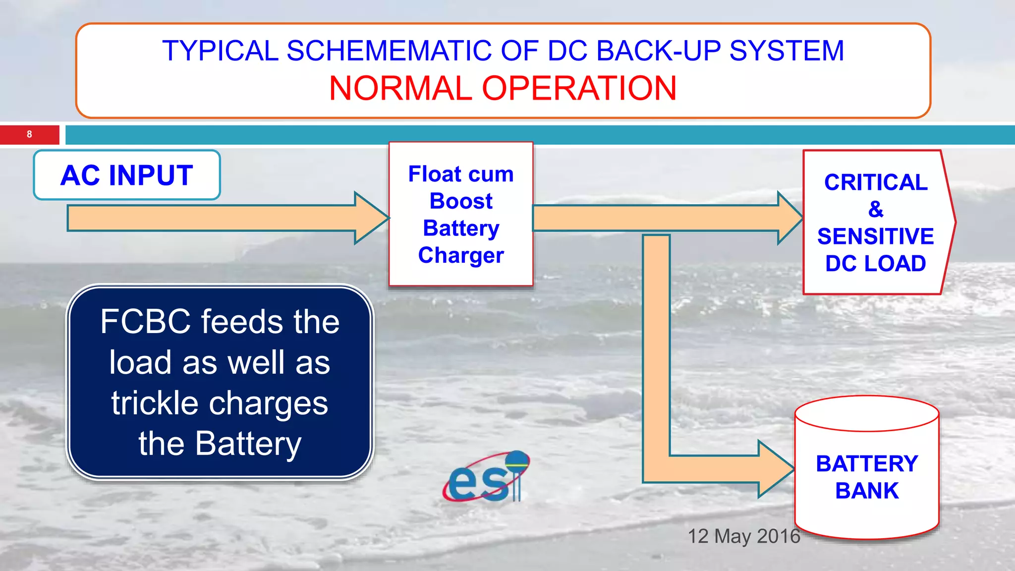
1) What a float cum boost battery charger is and its role in an uninterruptible DC power supply system.
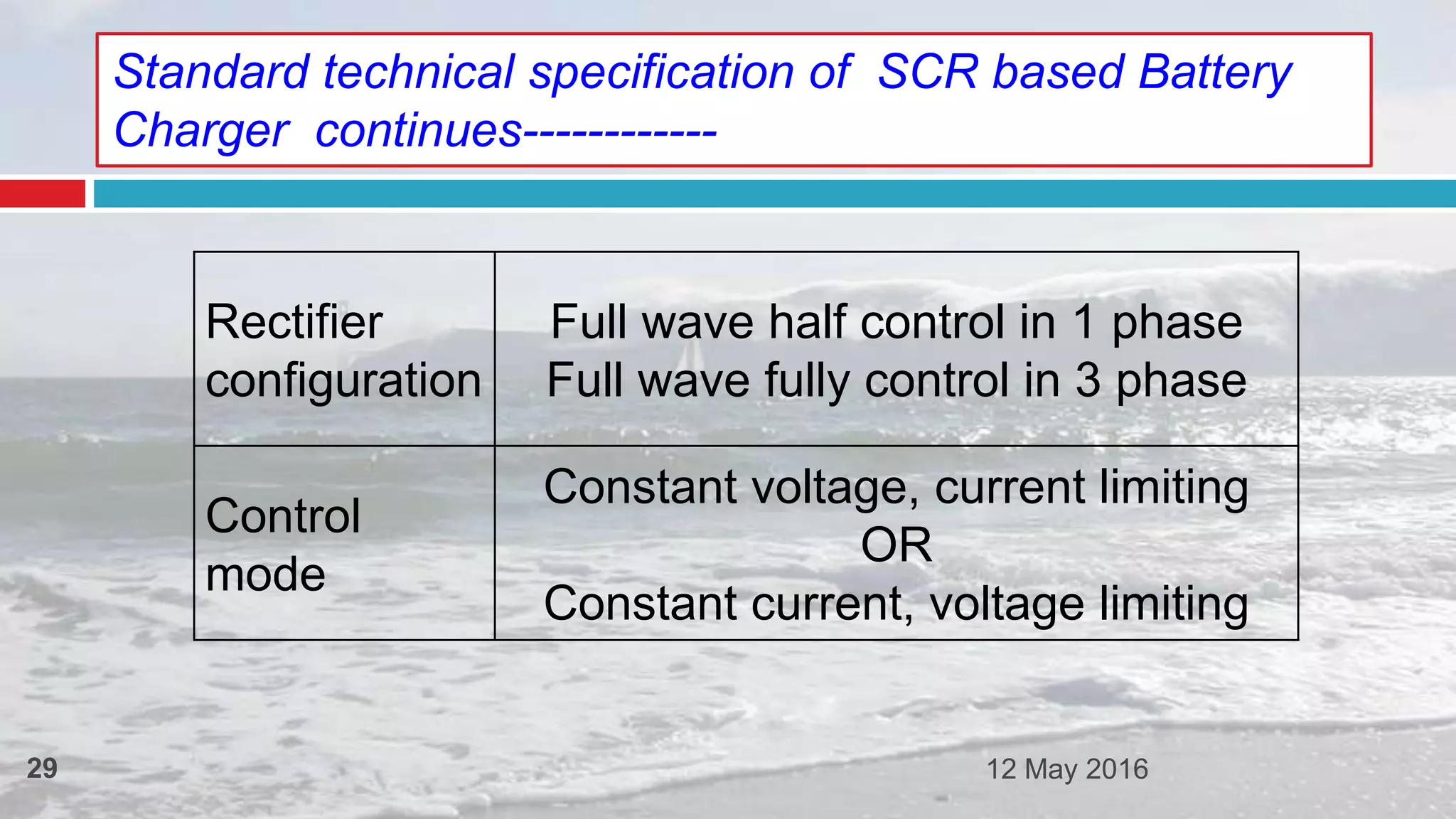
2) The topologies of float cum boost battery chargers, including single and dual rectifier designs.
3) The technical specifications of thyristor-controlled float chargers, including input/output voltages, regulation, protections, and construction.
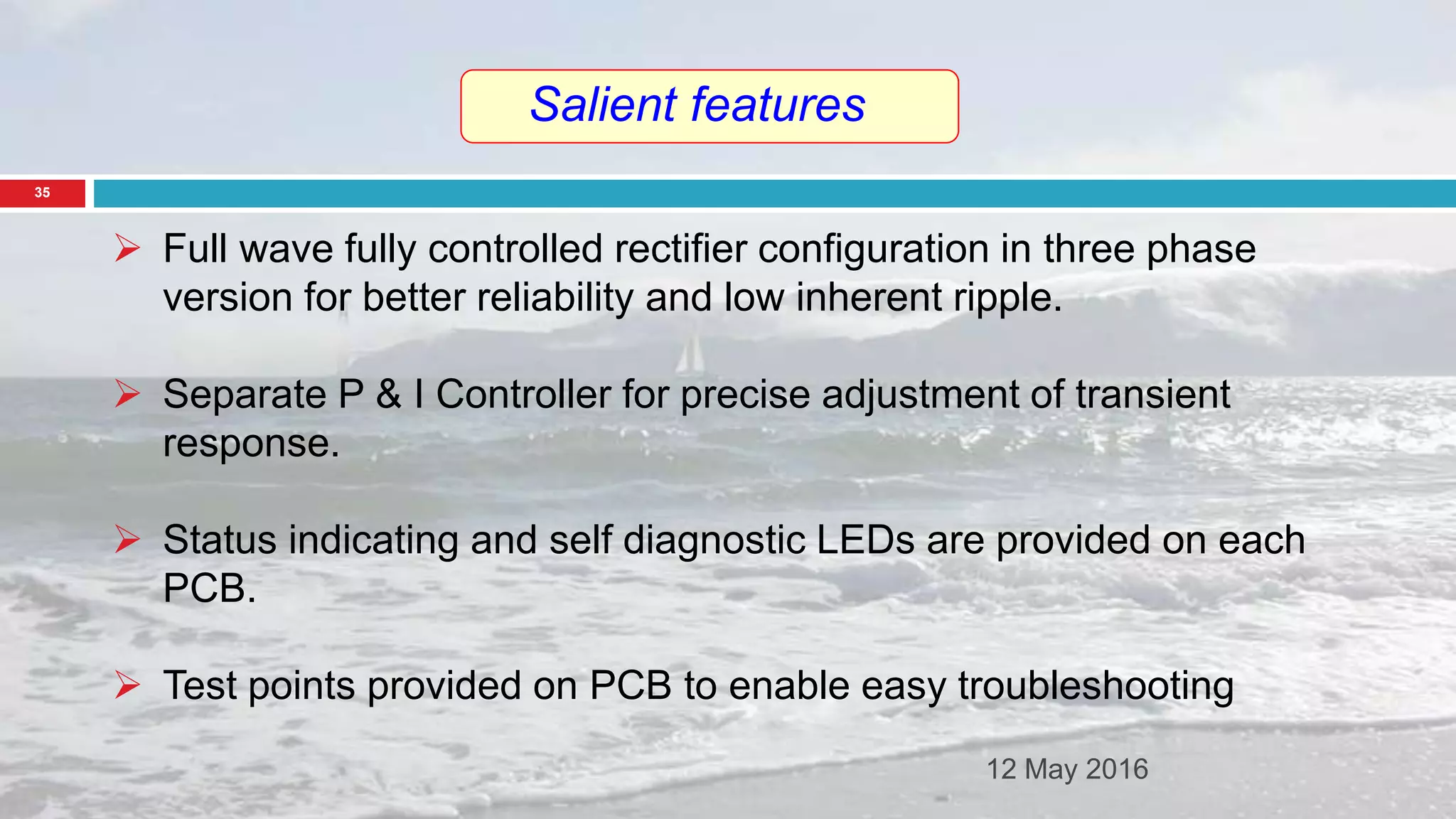
4) Salient features of thyristor-controlled float chargers like precise control, temperature compensation, automatic charging profiles, and modular design.
5) Present trends in converter technology moving from thyristor


![K1, DC1 -
CLOSED
K2-OPEN
FLOAT
RECTIFIER
[ON]
AC INPUT
BOOST
CHARGER
[OFF]
DC DISTRI-
-BUTION
BOARD
BATTERY
BANK
DC1
K1
K2
STAGE-1 :
NORMAL
OPERATION
Float rectifier feeds the load and trickle charges the Battery.
Boost charger remains in stand by OFF position
12 May 2016
16](https://image.slidesharecdn.com/fcbcpptver1-160512071353/75/ESI-Electro-Service-India-Float-Cum-Battery-Charger-16-2048.jpg)
![DC1 -CLOSED
K1, K2-OPEN
FLOAT
RECTIFIER
[NO SUPPLY]
AC INPUT
BOOST
CHARGER
[NO SUPPLY]
DC DISTRI-
-BUTION
BOARD
BATTERY
BANK
DC1
K1
K2
STAGE-2 :
POWER
OUTAGE
BATTERY BACK UP PERIOD
Battery feeds the Load
12 May 2016
17](https://image.slidesharecdn.com/fcbcpptver1-160512071353/75/ESI-Electro-Service-India-Float-Cum-Battery-Charger-17-2048.jpg)
![K1, K2 -
CLOSED
DC1-OPEN
FLOAT
RECTIFIER
[ON]
AC INPUT
BOOST
CHARGER
[ON]
DC DISTRI-
-BUTION
BOARD
BATTERY
BANK
DC1
K1
K2
STAGE-3
POWER
RESTORATION
BOOST CHARGING OF BATTERY AFTER DEEP DISCHARGE
Boost charger charges Battery when Float rectifier feeds load
12 May 2016
18](https://image.slidesharecdn.com/fcbcpptver1-160512071353/75/ESI-Electro-Service-India-Float-Cum-Battery-Charger-18-2048.jpg)
![K1, DC1 -
CLOSED
K2-OPEN
FLOAT
RECTIFIER
[ON]
AC INPUT
BOOST
CHARGER
[OFF]
DC DISTRI-
-BUTION
BOARD
BATTERY
BANK
DC1
K1
K2
STAGE-4:
BATTERY
CHARGED
Back to NORMAL operation.
Float rectifier feeding the load and trickle charging the Battery.
Boost charger remains in stand by OFF position
12 May 2016
19](https://image.slidesharecdn.com/fcbcpptver1-160512071353/75/ESI-Electro-Service-India-Float-Cum-Battery-Charger-19-2048.jpg)
![K1, K2 -
CLOSED
DC1-OPEN
AC INPUT
BOOST
CHARGER
[ON IN
FLOAT
MODE]
DC DISTRI--
BUTION
BOARD
BATTERY
BANK
DC1
K1
K2
STAGE-5
FLOAT RECT.
FAILED
EMERGENCY FLOAT MODE
Boost charger acts as Float rectifier feeding the load and
charging the Battery
12 May 2016
20](https://image.slidesharecdn.com/fcbcpptver1-160512071353/75/ESI-Electro-Service-India-Float-Cum-Battery-Charger-20-2048.jpg)


![SIX
PULSE
TRIGGER
CUM
CONTRO
L
PCB
[MOTHER
BOARD]
OUTPUT TO
6-PULSE
TRAFO
USER CONTROL POTS
12 May 2016
26](https://image.slidesharecdn.com/fcbcpptver1-160512071353/75/ESI-Electro-Service-India-Float-Cum-Battery-Charger-26-2048.jpg)