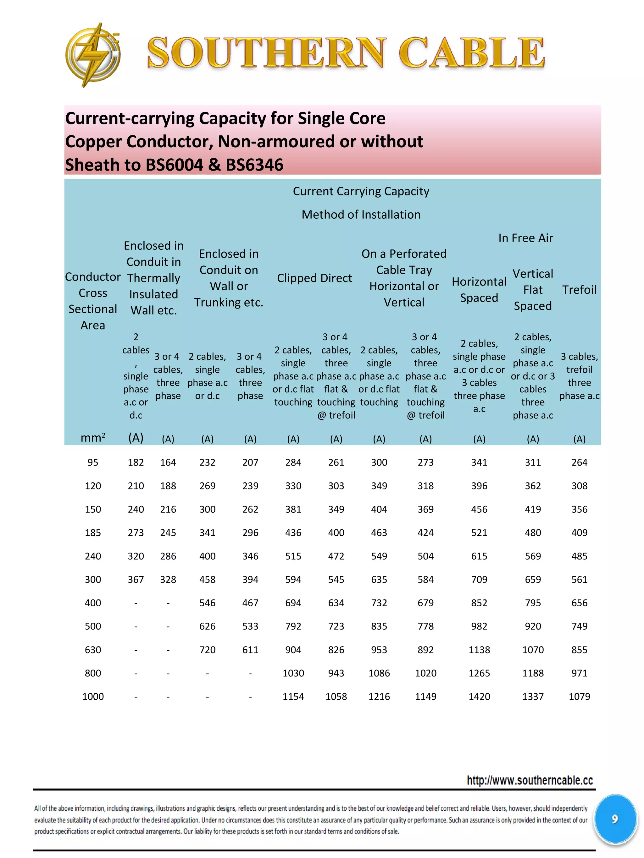
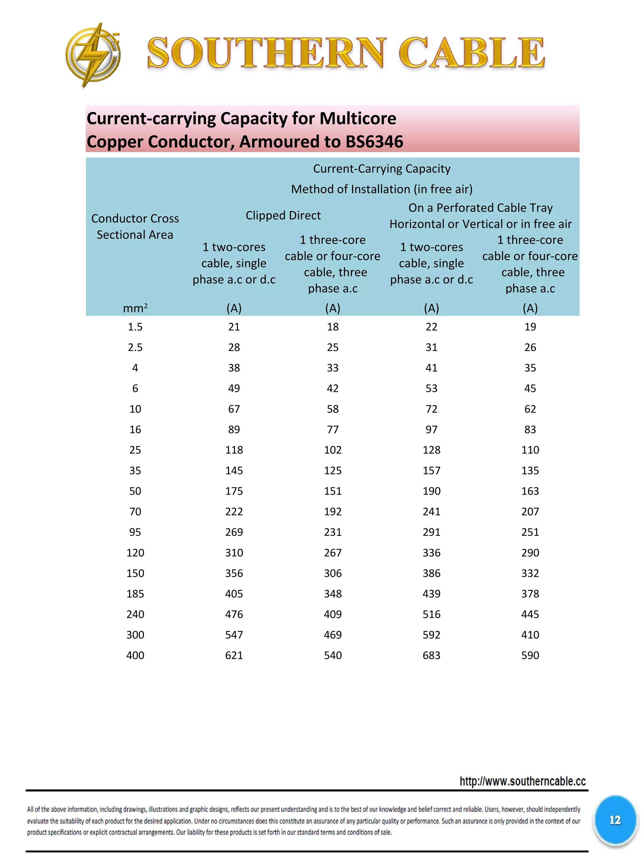
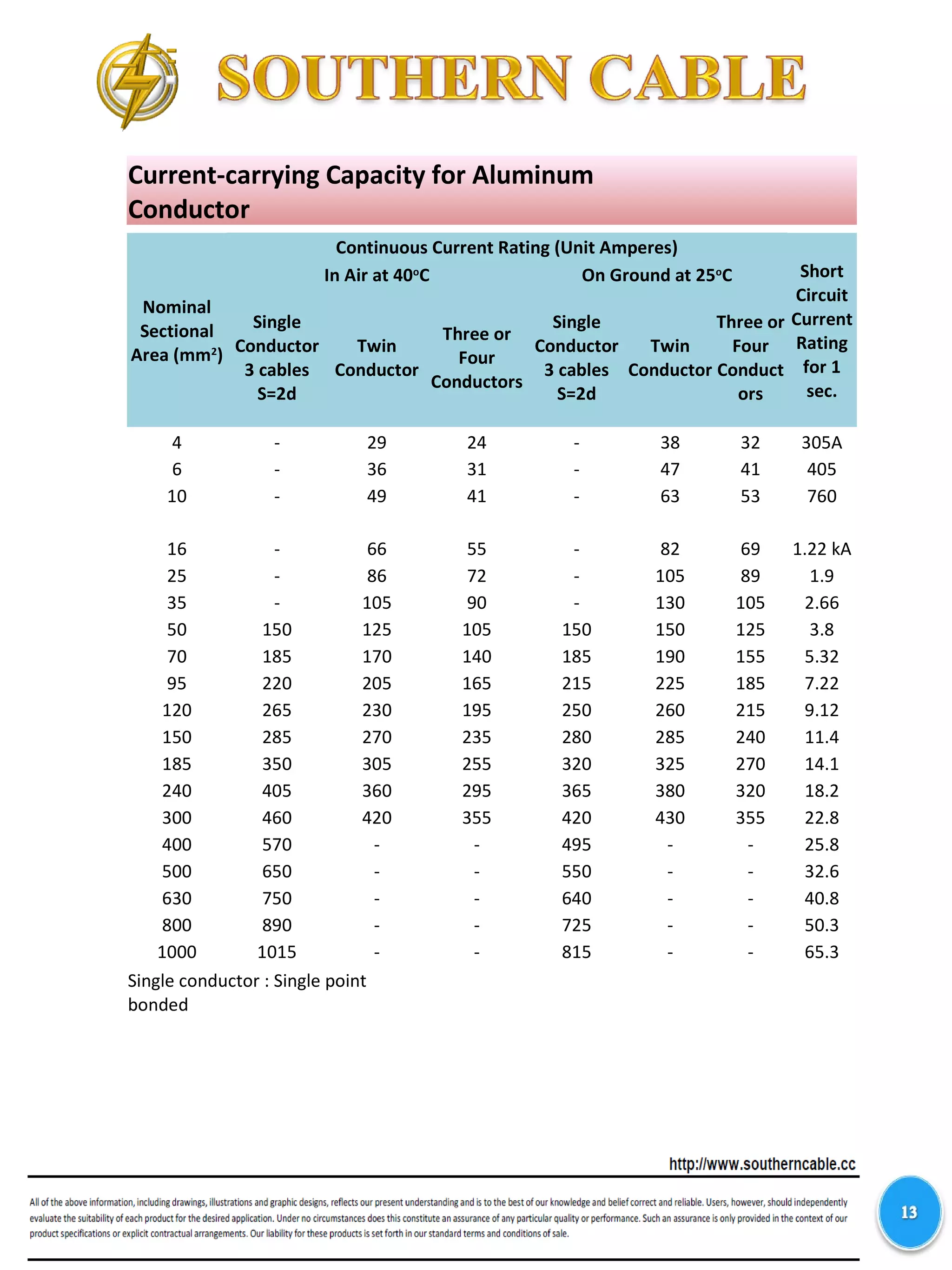
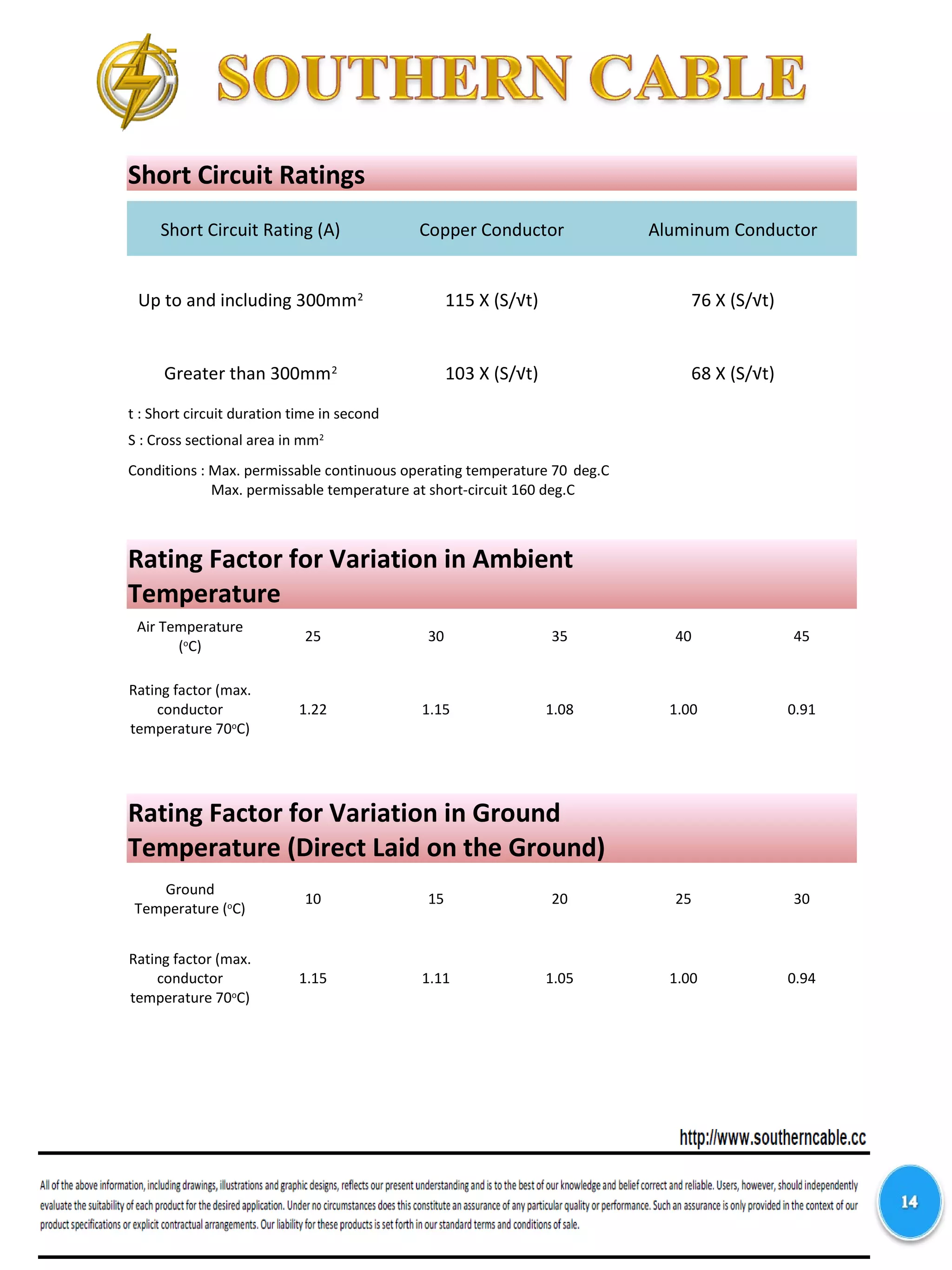
KL Office :
No.9-1 & 9-2, Jalan Puteri 5/20, Bandar Puteri,
47100 Puchong, Selangor
MALAYSIA
Tel : +603-80601222, +603-8061112, +80601100
Fax : +603-80601212
Website : www.southerncable.cc
Email : sc@southerncable.cc
Head Office & Factory :
Lot 42, Jalan Merbau Pulas,
Kawasan Perindustrian Kuala Ketil,
09300 Kuala Ketil, Baling, Kedah
MALAYSIA
Tel : +604-4161600 Fax : +604-4161599
Website : www.southerncable.cc
Email : sc@southerncable.cc
ISO9001 : 2000
Reg. No. : AR1757
Sheathed cables
clipped direct to
or lying on a non-
metallic surface
3 Reference to Table
Methods of Installation of Cables
Installation Method
Number Description
Installation Method Appropriate
Reference for
determining
Current-carrying
Capacity
Open and Clipped Direct
Sheathed cables
clipped direct to
or lying on a non-
metallic surface
1 Reference to Table
In Conduit
Single core non
sheathed cables
in metallic or
non-metallic
conduit on a wall
or ceiling
2 Reference to Table
Installation Method
Number Description
Installation Method Appropriate
Reference for
determining
Current-carrying
Capacity
In Trunking
Cables in trunking
on a wall or
suspended in air
8 Reference to Table
Cables in flush
floor trunking
9 Reference to Table
Single core cables
in skirting
trunking
10 Reference to Table
Methods of Installation of Cables
Installation Method
Number Description
Installation Method Appropriate
Reference for
determining
Current-carrying
Capacity
On Trays
Sheathed cables
on a perforated
cable tray,
bunched and
unenclosed. A
perforated cable
tray is considered
as a tray in which
the holes occupy
at least 30% of
the surface area.
11 Reference to Table
In Free Air
Sheathed single
core cables in
free air (any
supporting metal
work under the
cables occupying
less than 10% of
the plan area) :
2 or 3 cables
vertically one
above the other,
distance between
cables equal to
the overall
diameter (De);
distance from the
wall not less than
0.5 (De)
12 Reference to Table
Methods of Installation of Cables
Installation Method
Number Description
Installation Method Appropriate
Reference for
determining
Current-carrying
Capacity
In Free Air
Sheathed
Multicores cables
in free air
distance between
wall and cable
surface not less
than 0.3 De (any
supporting
metalwork
occupying less
than 10% of the
plan area)
13 Reference to Table
Methods of Installation of Cables
Nom. Cross
Sectional Area
for Cu.
Cu.
Conductor
Current
Rating
Voltage Drop
Cu. Conductor
Voltage Drop
Al. Conductor
Equivalent
Current Rating
of Al.
Conductor
Nom. Cross
Sectional
Area for Al.
mm2
(A) mV/A/m mV/A/m (A) mm2
1.5 18 25 11.82 28 6
2.5 25 15 11.82 28 6
4 33 9.5 7.91 39 10
6 43 6.4 4.2 57 16
10 59 3.8 4.2 57 16
16 79 2.4 2.7 79 25
25 104 1.5 1.35 123 35
35 129 1.1 1.35 123 50
50 167 0.84 0.94 159 70
70 214 0.6 0.58 226 120
95 261 0.47 0.48 261 150
120 303 0.4 0.41 299 185
150 349 0.34 0.35 354 240
185 400 0.31 0.31 410 300
240 472 0.27 0.28 472 400
300 545 0.25 0.26 546 500
400 634 0.24 0.24 626 630
500 723 0.23 0.23 709 800
630 826 0.22 0.22 823 1000
The continuos current carrying capacities are based on the following condition :
a) Ambient temperature 30oC
b) Maximum continuos loading temperature of conductor 70oC
c) Clipped direct 3 or 4 cable, 3 phase a.c
Cu and Al Equivalent Size Comparison
Nom. Cross
Sectional Area
for Cu.
Cu. Conductor
Current
Rating
Voltage Drop
Cu. Conductor
Voltage Drop
Al. Conductor
Equivalent
Current Rating
of Al.
Conductor
Nom. Cross
Sectional
Area for Al.
mm2
(A) mV/A/m mV/A/m (A) mm2
10 73 4 4.2 76 16
16 94 2.5 2.7 90 25
25 124 1.65 1.45 136 50
35 154 1.15 0.97 174 70
50 187 0.87 0.72 211 95
70 238 0.6 0.58 245 120
95 289 0.45 0.47 283 150
120 335 0.37 0.39 323 185
150 386 0.3 0.31 382 240
185 441 0.26 0.26 440 300
240 520 0.21 0.22 517 400
300 599 0.185 0.19 605 500
400 673 0.165 0.175 691 630
Cu and Al Equivalent Size Comparison
CU/XLPE/SWA/PVC/AL/XLPE/SCT/PE
The continuos current carrying capacities are based on the following condition :
a) Ambient temperature 30oC
b) Maximum continuos loading temperature of conductor 70oC
c) Clipped direct 3 or 4 cable, 3 phase a.c
Cu and Al Equivalent Size Comparison
XLPE/PVC
The continuos current carrying capacities are based on the following condition :
a) Ambient temperature 30 deg.C
b) Maximum continuos loading temperature of conductor 90 deg.C
c) Clipped direct 3 or 4 cable, 3 phase a.c
Nom. Cross
Sectional Area
for Cu.
Cu. Conductor
Current
Rating
Voltage Drop
Cu. Conductor
Voltage Drop
Al. Conductor
Equivalent
Current Rating
of Al.
Conductor
Nom. Cross
Sectional
Area for Al.
mm2
(A) mV/A/m mV/A/m (A) mm2
10 74 4 4.2 80 16
16 99 2.5 2.7 97 25
25 130 1.6 1.45 149 50
35 161 1.15 0.98 189 70
50 209 0.87 0.73 234 95
70 268 0.61 0.59 273 120
95 326 0.45 0.47 314 150
120 379 0.37 0.39 366 185
150 436 0.31 0.32 438 240
185 500 0.26 0.27 507 300
240 590 0.22 0.23 594 400
300 681 0.195 0.2 692 500
400 793 0.175 0.185 791 630
500 904 0.16 0.17 911 800
630 1033 0.15 0.16 1072 1000
800 1179 0.145 0.15 1217 1200
Current-carrying Capacity for Single Core
Copper Conductor, Non-armoured or without
Sheath to BS6004 & BS6346
Conductor
Cross
Sectional
Area
Current Carrying Capacity
Method of Installation
Enclosed in
Conduit in
Thermally
Insulated Wall
etc.
Enclosed in
Conduit on
Wall or
Trunking etc.
Clipped Direct
On a
Perforated
Cable Tray
Horizontal or
Vertical
In Free Air
Horizontal
Spaced
Vertical
Flat
Spaced
Trefoil
2
cables,
single
phase
a.c or
d.c
3 or 4
cables,
three
phase
2
cables,
single
phase
a.c or
d.c
3 or 4
cables,
three
phase
2 cables,
single
phase a.c
or d.c flat
touching
3 or 4
cables,
three
phase a.c
flat &
touching
@ trefoil
2 cables,
single
phase a.c
or d.c flat
touching
3 or 4
cables,
three
phase a.c
flat &
touching
@ trefoil
2 cables,
single phase
a.c or d.c or
3 cables
three phase
a.c
2 cables,
single
phase a.c
or d.c or 3
cables
three
phase a.c
3
cables,
trefoil
three
phase
a.c
mm2
(A) (A) (A) (A) (A) (A) (A) (A) (A) (A) (A)
1.25 13 12 16 14 19 17 - - - - -
1.5 14.5 13.5 17.5 15.5 20 18 - - - - -
2.5 19.5 18 24 21 27 25 - - - - -
4 26 24 32 28 37 33 - - - - -
6 34 31 41 36 47 43 - - - - -
10 46 42 57 50 65 59 - - - - -
16 61 56 76 68 87 79 - - - - -
25 80 73 101 89 114 104 126 112 146 130 110
35 99 89 125 110 141 129 156 141 181 162 137
50 119 108 151 134 182 167 191 172 219 197 167
70 151 136 192 171 234 214 246 223 281 254 216
Current-carrying Capacity for Single Core
Copper Conductor, Non-armoured or without
Sheath to BS6004 & BS6346
Conductor
Cross
Sectional
Area
Current Carrying Capacity
Method of Installation
Enclosed in
Conduit in
Thermally
Insulated
Wall etc.
Enclosed in
Conduit on
Wall or
Trunking etc.
Clipped Direct
On a Perforated
Cable Tray
Horizontal or
Vertical
In Free Air
Horizontal
Spaced
Vertical
Flat
Spaced
Trefoil
2
cables
,
single
phase
a.c or
d.c
3 or 4
cables,
three
phase
2 cables,
single
phase a.c
or d.c
3 or 4
cables,
three
phase
2 cables,
single
phase a.c
or d.c flat
touching
3 or 4
cables,
three
phase a.c
flat &
touching
@ trefoil
2 cables,
single
phase a.c
or d.c flat
touching
3 or 4
cables,
three
phase a.c
flat &
touching
@ trefoil
2 cables,
single phase
a.c or d.c or
3 cables
three phase
a.c
2 cables,
single
phase a.c
or d.c or 3
cables
three
phase a.c
3 cables,
trefoil
three
phase a.c
mm2
(A) (A) (A) (A) (A) (A) (A) (A) (A) (A) (A)
95 182 164 232 207 284 261 300 273 341 311 264
120 210 188 269 239 330 303 349 318 396 362 308
150 240 216 300 262 381 349 404 369 456 419 356
185 273 245 341 296 436 400 463 424 521 480 409
240 320 286 400 346 515 472 549 504 615 569 485
300 367 328 458 394 594 545 635 584 709 659 561
400 - - 546 467 694 634 732 679 852 795 656
500 - - 626 533 792 723 835 778 982 920 749
630 - - 720 611 904 826 953 892 1138 1070 855
800 - - - - 1030 943 1086 1020 1265 1188 971
1000 - - - - 1154 1058 1216 1149 1420 1337 1079
Current-carrying Capacity for Multicore
Copper Conductor, Non-armoured to BS6004
& BS6346
Conductor
Cross
Sectional
Area
Current Carrying Capacity
Method of Installation
Enclosed in
Conduit in
Thermally
Insulated Wall etc.
Enclosed in Conduit on
Wall or Trunking etc.
Clipped Direct
On a Perforated
Cable Tray
Horizontal or
Vertical
1 two-
cores
cable,
single
phase
a.c or
d.c
1 three-
core cable
or four-
core
cable,
three
phase a.c
1 two-
cores
cable,
single
phase a.c
or d.c
1 three-
core cable
or four-
core
cable,
three
phase a.c
1 two-
cores
cable,
single
phase a.c
or d.c
1 three-
core cable
or four-
core
cable,
three
phase a.c
1 two-
cores
cable,
single
phase
a.c or d.c
1 three-
core cable
or four-
core
cable,
three
phase a.c
mm2
(A) (A) (A) (A) (A) (A) (A) (A)
1.5 14 13 16.5 15 19.5 17.5 22 18.5
2.5 18.5 17.5 23 20 27 24 30 25
4 25 23 30 27 36 32 40 34
6 32 29 38 34 46 41 51 43
10 43 39 52 46 63 57 70 60
16 57 52 69 62 85 76 94 80
25 75 68 90 80 112 96 119 101
35 92 83 111 99 138 119 148 126
50 110 99 133 118 168 144 180 153
70 139 125 168 149 213 184 232 196
95 167 150 201 179 258 223 282 238
120 192 172 232 206 299 259 328 276
150 219 196 258 225 344 299 378 319
185 248 223 294 255 392 341 434 364
240 291 261 344 297 461 403 514 430
300 334 298 394 339 530 464 593 497
400 - - 470 402 634 557 715 597
Current-carrying Capacity for Single Core
Copper Conductor, Armoured to BS6346
Conductor
Cross
Sectional
Area
Current-Carrying Capacity
Method of Installation (in free air)
Clipped Direct
On a Perforated Cable
Tray Horizontal or
Vertical
2 cables, single
phase a.c
2 cables, single
phase d.c
3 or 4 cables, three
phase a.c
2 cables,
single phase
a.c or d.c
flat &
touching
3 or 4
cables,
three phase
a.c, flat &
touching
2 cables,
single phase
a.c or d.c
flat &
touching
3 or 4
cables,
three phase
a.c, flat &
touching
Horizontal
Spaced
Vertical
Flat
Spaced
Horizont
al
Spaced
Vertical
Flat
Spaced
Horizon
tal
Spaced
Vertical
Flat
Spaced
3 cables
Trefoil
mm2
(A) (A) (A) (A) (A) (A) (A) (A) (A) (A) (A)
50 193 179 205 189 229 217 229 216 230 212 181
70 245 225 259 238 287 272 294 279 286 263 231
95 296 269 313 285 349 332 357 340 338 313 280
120 342 309 360 327 401 383 415 396 385 357 324
150 395 354 413 373 456 436 479 461 438 407 373
185 447 399 469 422 511 489 548 525 490 456 425
240 525 465 550 492 593 568 648 622 566 528 501
300 594 515 624 547 668 640 748 719 616 578 567
400 687 575 723 618 737 707 885 851 674 632 657
500 763 622 805 673 810 777 1035 997 721 676 731
630 843 669 891 728 893 856 1218 1174 771 723 809
800 919 710 976 777 943 905 1441 1390 824 772 866
1000 975 737 1041 808 1008 967 1685 1627 872 816 945
Current-carrying Capacity for Multicore
Copper Conductor, Armoured to BS6346
Conductor Cross
Sectional Area
Current-Carrying Capacity
Method of Installation (in free air)
Clipped Direct
On a Perforated Cable Tray
Horizontal or Vertical or in free air
1 two-cores
cable, single
phase a.c or d.c
1 three-core
cable or four-core
cable, three
phase a.c
1 two-cores
cable, single
phase a.c or d.c
1 three-core
cable or four-core
cable, three
phase a.c
mm2
(A) (A) (A) (A)
1.5 21 18 22 19
2.5 28 25 31 26
4 38 33 41 35
6 49 42 53 45
10 67 58 72 62
16 89 77 97 83
25 118 102 128 110
35 145 125 157 135
50 175 151 190 163
70 222 192 241 207
95 269 231 291 251
120 310 267 336 290
150 356 306 386 332
185 405 348 439 378
240 476 409 516 445
300 547 469 592 410
400 621 540 683 590
Current-carrying Capacity for Aluminum
Conductor
Nominal
Sectional
Area (mm2
)
Continuous Current Rating (Unit Amperes)
Short
Circuit
Current
Rating
for 1
sec.
In Air at 40o
C On Ground at 25o
C
Single
Conductor
3 cables
S=2d
Twin
Conductor
Three or
Four
Conductors
Single
Conductor
3 cables
S=2d
Twin
Conductor
Three or
Four
Conduct
ors
4 - 29 24 - 38 32 305A
6 - 36 31 - 47 41 405
10 - 49 41 - 63 53 760
16 - 66 55 - 82 69 1.22 kA
25 - 86 72 - 105 89 1.9
35 - 105 90 - 130 105 2.66
50 150 125 105 150 150 125 3.8
70 185 170 140 185 190 155 5.32
95 220 205 165 215 225 185 7.22
120 265 230 195 250 260 215 9.12
150 285 270 235 280 285 240 11.4
185 350 305 255 320 325 270 14.1
240 405 360 295 365 380 320 18.2
300 460 420 355 420 430 355 22.8
400 570 - - 495 - - 25.8
500 650 - - 550 - - 32.6
630 750 - - 640 - - 40.8
800 890 - - 725 - - 50.3
1000 1015 - - 815 - - 65.3
Single conductor : Single point
bonded
Short Circuit Ratings
Short Circuit Rating (A) Copper Conductor Aluminum Conductor
Up to and including 300mm2
115 X (S/√t) 76 X (S/√t)
Greater than 300mm2
103 X (S/√t) 68 X (S/√t)
t : Short circuit duration time in second
S : Cross sectional area in mm2
Conditions : Max. permissable continuous operating temperature 70 deg.C
Max. permissable temperature at short-circuit 160 deg.C
Air Temperature
(o
C)
25 30 35 40 45
Rating factor (max.
conductor
temperature 70o
C)
1.22 1.15 1.08 1.00 0.91
Rating Factor for Variation in Ambient
Temperature
Ground
Temperature (o
C)
10 15 20 25 30
Rating factor (max.
conductor
temperature 70o
C)
1.15 1.11 1.05 1.00 0.94
Rating Factor for Variation in Ground
Temperature (Direct Laid on the Ground)
Rating Factors for Depth Laying for Cables
Laid Direct on the Ground
Depth of Laying
(meter)
600/1000V Cables
Up to 50 mm2
70 mm2 to 300 mm2
Above 300 mm2
0.5 1.03 1.04 1.06
0.6 1.02 1.02 1.03
0.8 1.00 1.00 1.00
1 0.98 0.97 0.98
1.25 0.97 0.96 0.95
1.5 0.96 0.94 0.93
1.75 0.95 0.93 0.91
2 0.94 0.92 0.90
2.5 0.93 0.91 0.89
3.0 and above 0.92 0.89 0.87
HANDLING AND INSTALLATION OF CABLE
1.Minimum bending radius and permissable pulling tension
- to prevent damage on electrical and physical properties of the cable
Lifting by crane Drum rolling direction Do not lay on flanges
Lifting drum by forklift correctly
Drums secure adequately during transportation
HANDLING AND INSTALLATION OF CABLE
DO NOT attempt “coiling” on the ground
On the ground cable can be FLAKED in a figure of eight formation
HANDLING AND INSTALLATION OF CABLE

21 handling & installation of cables

  • 1.
    KL Office : No.9-1& 9-2, Jalan Puteri 5/20, Bandar Puteri, 47100 Puchong, Selangor MALAYSIA Tel : +603-80601222, +603-8061112, +80601100 Fax : +603-80601212 Website : www.southerncable.cc Email : sc@southerncable.cc Head Office & Factory : Lot 42, Jalan Merbau Pulas, Kawasan Perindustrian Kuala Ketil, 09300 Kuala Ketil, Baling, Kedah MALAYSIA Tel : +604-4161600 Fax : +604-4161599 Website : www.southerncable.cc Email : sc@southerncable.cc ISO9001 : 2000 Reg. No. : AR1757
  • 2.
    Sheathed cables clipped directto or lying on a non- metallic surface 3 Reference to Table Methods of Installation of Cables Installation Method Number Description Installation Method Appropriate Reference for determining Current-carrying Capacity Open and Clipped Direct Sheathed cables clipped direct to or lying on a non- metallic surface 1 Reference to Table In Conduit Single core non sheathed cables in metallic or non-metallic conduit on a wall or ceiling 2 Reference to Table
  • 3.
    Installation Method Number Description InstallationMethod Appropriate Reference for determining Current-carrying Capacity In Trunking Cables in trunking on a wall or suspended in air 8 Reference to Table Cables in flush floor trunking 9 Reference to Table Single core cables in skirting trunking 10 Reference to Table Methods of Installation of Cables
  • 4.
    Installation Method Number Description InstallationMethod Appropriate Reference for determining Current-carrying Capacity On Trays Sheathed cables on a perforated cable tray, bunched and unenclosed. A perforated cable tray is considered as a tray in which the holes occupy at least 30% of the surface area. 11 Reference to Table In Free Air Sheathed single core cables in free air (any supporting metal work under the cables occupying less than 10% of the plan area) : 2 or 3 cables vertically one above the other, distance between cables equal to the overall diameter (De); distance from the wall not less than 0.5 (De) 12 Reference to Table Methods of Installation of Cables
  • 5.
    Installation Method Number Description InstallationMethod Appropriate Reference for determining Current-carrying Capacity In Free Air Sheathed Multicores cables in free air distance between wall and cable surface not less than 0.3 De (any supporting metalwork occupying less than 10% of the plan area) 13 Reference to Table Methods of Installation of Cables
  • 6.
    Nom. Cross Sectional Area forCu. Cu. Conductor Current Rating Voltage Drop Cu. Conductor Voltage Drop Al. Conductor Equivalent Current Rating of Al. Conductor Nom. Cross Sectional Area for Al. mm2 (A) mV/A/m mV/A/m (A) mm2 1.5 18 25 11.82 28 6 2.5 25 15 11.82 28 6 4 33 9.5 7.91 39 10 6 43 6.4 4.2 57 16 10 59 3.8 4.2 57 16 16 79 2.4 2.7 79 25 25 104 1.5 1.35 123 35 35 129 1.1 1.35 123 50 50 167 0.84 0.94 159 70 70 214 0.6 0.58 226 120 95 261 0.47 0.48 261 150 120 303 0.4 0.41 299 185 150 349 0.34 0.35 354 240 185 400 0.31 0.31 410 300 240 472 0.27 0.28 472 400 300 545 0.25 0.26 546 500 400 634 0.24 0.24 626 630 500 723 0.23 0.23 709 800 630 826 0.22 0.22 823 1000 The continuos current carrying capacities are based on the following condition : a) Ambient temperature 30oC b) Maximum continuos loading temperature of conductor 70oC c) Clipped direct 3 or 4 cable, 3 phase a.c Cu and Al Equivalent Size Comparison
  • 7.
    Nom. Cross Sectional Area forCu. Cu. Conductor Current Rating Voltage Drop Cu. Conductor Voltage Drop Al. Conductor Equivalent Current Rating of Al. Conductor Nom. Cross Sectional Area for Al. mm2 (A) mV/A/m mV/A/m (A) mm2 10 73 4 4.2 76 16 16 94 2.5 2.7 90 25 25 124 1.65 1.45 136 50 35 154 1.15 0.97 174 70 50 187 0.87 0.72 211 95 70 238 0.6 0.58 245 120 95 289 0.45 0.47 283 150 120 335 0.37 0.39 323 185 150 386 0.3 0.31 382 240 185 441 0.26 0.26 440 300 240 520 0.21 0.22 517 400 300 599 0.185 0.19 605 500 400 673 0.165 0.175 691 630 Cu and Al Equivalent Size Comparison CU/XLPE/SWA/PVC/AL/XLPE/SCT/PE The continuos current carrying capacities are based on the following condition : a) Ambient temperature 30oC b) Maximum continuos loading temperature of conductor 70oC c) Clipped direct 3 or 4 cable, 3 phase a.c
  • 8.
    Cu and AlEquivalent Size Comparison XLPE/PVC The continuos current carrying capacities are based on the following condition : a) Ambient temperature 30 deg.C b) Maximum continuos loading temperature of conductor 90 deg.C c) Clipped direct 3 or 4 cable, 3 phase a.c Nom. Cross Sectional Area for Cu. Cu. Conductor Current Rating Voltage Drop Cu. Conductor Voltage Drop Al. Conductor Equivalent Current Rating of Al. Conductor Nom. Cross Sectional Area for Al. mm2 (A) mV/A/m mV/A/m (A) mm2 10 74 4 4.2 80 16 16 99 2.5 2.7 97 25 25 130 1.6 1.45 149 50 35 161 1.15 0.98 189 70 50 209 0.87 0.73 234 95 70 268 0.61 0.59 273 120 95 326 0.45 0.47 314 150 120 379 0.37 0.39 366 185 150 436 0.31 0.32 438 240 185 500 0.26 0.27 507 300 240 590 0.22 0.23 594 400 300 681 0.195 0.2 692 500 400 793 0.175 0.185 791 630 500 904 0.16 0.17 911 800 630 1033 0.15 0.16 1072 1000 800 1179 0.145 0.15 1217 1200
  • 9.
    Current-carrying Capacity forSingle Core Copper Conductor, Non-armoured or without Sheath to BS6004 & BS6346 Conductor Cross Sectional Area Current Carrying Capacity Method of Installation Enclosed in Conduit in Thermally Insulated Wall etc. Enclosed in Conduit on Wall or Trunking etc. Clipped Direct On a Perforated Cable Tray Horizontal or Vertical In Free Air Horizontal Spaced Vertical Flat Spaced Trefoil 2 cables, single phase a.c or d.c 3 or 4 cables, three phase 2 cables, single phase a.c or d.c 3 or 4 cables, three phase 2 cables, single phase a.c or d.c flat touching 3 or 4 cables, three phase a.c flat & touching @ trefoil 2 cables, single phase a.c or d.c flat touching 3 or 4 cables, three phase a.c flat & touching @ trefoil 2 cables, single phase a.c or d.c or 3 cables three phase a.c 2 cables, single phase a.c or d.c or 3 cables three phase a.c 3 cables, trefoil three phase a.c mm2 (A) (A) (A) (A) (A) (A) (A) (A) (A) (A) (A) 1.25 13 12 16 14 19 17 - - - - - 1.5 14.5 13.5 17.5 15.5 20 18 - - - - - 2.5 19.5 18 24 21 27 25 - - - - - 4 26 24 32 28 37 33 - - - - - 6 34 31 41 36 47 43 - - - - - 10 46 42 57 50 65 59 - - - - - 16 61 56 76 68 87 79 - - - - - 25 80 73 101 89 114 104 126 112 146 130 110 35 99 89 125 110 141 129 156 141 181 162 137 50 119 108 151 134 182 167 191 172 219 197 167 70 151 136 192 171 234 214 246 223 281 254 216
  • 10.
    Current-carrying Capacity forSingle Core Copper Conductor, Non-armoured or without Sheath to BS6004 & BS6346 Conductor Cross Sectional Area Current Carrying Capacity Method of Installation Enclosed in Conduit in Thermally Insulated Wall etc. Enclosed in Conduit on Wall or Trunking etc. Clipped Direct On a Perforated Cable Tray Horizontal or Vertical In Free Air Horizontal Spaced Vertical Flat Spaced Trefoil 2 cables , single phase a.c or d.c 3 or 4 cables, three phase 2 cables, single phase a.c or d.c 3 or 4 cables, three phase 2 cables, single phase a.c or d.c flat touching 3 or 4 cables, three phase a.c flat & touching @ trefoil 2 cables, single phase a.c or d.c flat touching 3 or 4 cables, three phase a.c flat & touching @ trefoil 2 cables, single phase a.c or d.c or 3 cables three phase a.c 2 cables, single phase a.c or d.c or 3 cables three phase a.c 3 cables, trefoil three phase a.c mm2 (A) (A) (A) (A) (A) (A) (A) (A) (A) (A) (A) 95 182 164 232 207 284 261 300 273 341 311 264 120 210 188 269 239 330 303 349 318 396 362 308 150 240 216 300 262 381 349 404 369 456 419 356 185 273 245 341 296 436 400 463 424 521 480 409 240 320 286 400 346 515 472 549 504 615 569 485 300 367 328 458 394 594 545 635 584 709 659 561 400 - - 546 467 694 634 732 679 852 795 656 500 - - 626 533 792 723 835 778 982 920 749 630 - - 720 611 904 826 953 892 1138 1070 855 800 - - - - 1030 943 1086 1020 1265 1188 971 1000 - - - - 1154 1058 1216 1149 1420 1337 1079
  • 11.
    Current-carrying Capacity forMulticore Copper Conductor, Non-armoured to BS6004 & BS6346 Conductor Cross Sectional Area Current Carrying Capacity Method of Installation Enclosed in Conduit in Thermally Insulated Wall etc. Enclosed in Conduit on Wall or Trunking etc. Clipped Direct On a Perforated Cable Tray Horizontal or Vertical 1 two- cores cable, single phase a.c or d.c 1 three- core cable or four- core cable, three phase a.c 1 two- cores cable, single phase a.c or d.c 1 three- core cable or four- core cable, three phase a.c 1 two- cores cable, single phase a.c or d.c 1 three- core cable or four- core cable, three phase a.c 1 two- cores cable, single phase a.c or d.c 1 three- core cable or four- core cable, three phase a.c mm2 (A) (A) (A) (A) (A) (A) (A) (A) 1.5 14 13 16.5 15 19.5 17.5 22 18.5 2.5 18.5 17.5 23 20 27 24 30 25 4 25 23 30 27 36 32 40 34 6 32 29 38 34 46 41 51 43 10 43 39 52 46 63 57 70 60 16 57 52 69 62 85 76 94 80 25 75 68 90 80 112 96 119 101 35 92 83 111 99 138 119 148 126 50 110 99 133 118 168 144 180 153 70 139 125 168 149 213 184 232 196 95 167 150 201 179 258 223 282 238 120 192 172 232 206 299 259 328 276 150 219 196 258 225 344 299 378 319 185 248 223 294 255 392 341 434 364 240 291 261 344 297 461 403 514 430 300 334 298 394 339 530 464 593 497 400 - - 470 402 634 557 715 597
  • 12.
    Current-carrying Capacity forSingle Core Copper Conductor, Armoured to BS6346 Conductor Cross Sectional Area Current-Carrying Capacity Method of Installation (in free air) Clipped Direct On a Perforated Cable Tray Horizontal or Vertical 2 cables, single phase a.c 2 cables, single phase d.c 3 or 4 cables, three phase a.c 2 cables, single phase a.c or d.c flat & touching 3 or 4 cables, three phase a.c, flat & touching 2 cables, single phase a.c or d.c flat & touching 3 or 4 cables, three phase a.c, flat & touching Horizontal Spaced Vertical Flat Spaced Horizont al Spaced Vertical Flat Spaced Horizon tal Spaced Vertical Flat Spaced 3 cables Trefoil mm2 (A) (A) (A) (A) (A) (A) (A) (A) (A) (A) (A) 50 193 179 205 189 229 217 229 216 230 212 181 70 245 225 259 238 287 272 294 279 286 263 231 95 296 269 313 285 349 332 357 340 338 313 280 120 342 309 360 327 401 383 415 396 385 357 324 150 395 354 413 373 456 436 479 461 438 407 373 185 447 399 469 422 511 489 548 525 490 456 425 240 525 465 550 492 593 568 648 622 566 528 501 300 594 515 624 547 668 640 748 719 616 578 567 400 687 575 723 618 737 707 885 851 674 632 657 500 763 622 805 673 810 777 1035 997 721 676 731 630 843 669 891 728 893 856 1218 1174 771 723 809 800 919 710 976 777 943 905 1441 1390 824 772 866 1000 975 737 1041 808 1008 967 1685 1627 872 816 945
  • 13.
    Current-carrying Capacity forMulticore Copper Conductor, Armoured to BS6346 Conductor Cross Sectional Area Current-Carrying Capacity Method of Installation (in free air) Clipped Direct On a Perforated Cable Tray Horizontal or Vertical or in free air 1 two-cores cable, single phase a.c or d.c 1 three-core cable or four-core cable, three phase a.c 1 two-cores cable, single phase a.c or d.c 1 three-core cable or four-core cable, three phase a.c mm2 (A) (A) (A) (A) 1.5 21 18 22 19 2.5 28 25 31 26 4 38 33 41 35 6 49 42 53 45 10 67 58 72 62 16 89 77 97 83 25 118 102 128 110 35 145 125 157 135 50 175 151 190 163 70 222 192 241 207 95 269 231 291 251 120 310 267 336 290 150 356 306 386 332 185 405 348 439 378 240 476 409 516 445 300 547 469 592 410 400 621 540 683 590
  • 14.
    Current-carrying Capacity forAluminum Conductor Nominal Sectional Area (mm2 ) Continuous Current Rating (Unit Amperes) Short Circuit Current Rating for 1 sec. In Air at 40o C On Ground at 25o C Single Conductor 3 cables S=2d Twin Conductor Three or Four Conductors Single Conductor 3 cables S=2d Twin Conductor Three or Four Conduct ors 4 - 29 24 - 38 32 305A 6 - 36 31 - 47 41 405 10 - 49 41 - 63 53 760 16 - 66 55 - 82 69 1.22 kA 25 - 86 72 - 105 89 1.9 35 - 105 90 - 130 105 2.66 50 150 125 105 150 150 125 3.8 70 185 170 140 185 190 155 5.32 95 220 205 165 215 225 185 7.22 120 265 230 195 250 260 215 9.12 150 285 270 235 280 285 240 11.4 185 350 305 255 320 325 270 14.1 240 405 360 295 365 380 320 18.2 300 460 420 355 420 430 355 22.8 400 570 - - 495 - - 25.8 500 650 - - 550 - - 32.6 630 750 - - 640 - - 40.8 800 890 - - 725 - - 50.3 1000 1015 - - 815 - - 65.3 Single conductor : Single point bonded
  • 15.
    Short Circuit Ratings ShortCircuit Rating (A) Copper Conductor Aluminum Conductor Up to and including 300mm2 115 X (S/√t) 76 X (S/√t) Greater than 300mm2 103 X (S/√t) 68 X (S/√t) t : Short circuit duration time in second S : Cross sectional area in mm2 Conditions : Max. permissable continuous operating temperature 70 deg.C Max. permissable temperature at short-circuit 160 deg.C Air Temperature (o C) 25 30 35 40 45 Rating factor (max. conductor temperature 70o C) 1.22 1.15 1.08 1.00 0.91 Rating Factor for Variation in Ambient Temperature Ground Temperature (o C) 10 15 20 25 30 Rating factor (max. conductor temperature 70o C) 1.15 1.11 1.05 1.00 0.94 Rating Factor for Variation in Ground Temperature (Direct Laid on the Ground)
  • 16.
    Rating Factors forDepth Laying for Cables Laid Direct on the Ground Depth of Laying (meter) 600/1000V Cables Up to 50 mm2 70 mm2 to 300 mm2 Above 300 mm2 0.5 1.03 1.04 1.06 0.6 1.02 1.02 1.03 0.8 1.00 1.00 1.00 1 0.98 0.97 0.98 1.25 0.97 0.96 0.95 1.5 0.96 0.94 0.93 1.75 0.95 0.93 0.91 2 0.94 0.92 0.90 2.5 0.93 0.91 0.89 3.0 and above 0.92 0.89 0.87
  • 17.
    HANDLING AND INSTALLATIONOF CABLE 1.Minimum bending radius and permissable pulling tension - to prevent damage on electrical and physical properties of the cable
  • 18.
    Lifting by craneDrum rolling direction Do not lay on flanges Lifting drum by forklift correctly Drums secure adequately during transportation HANDLING AND INSTALLATION OF CABLE
  • 19.
    DO NOT attempt“coiling” on the ground On the ground cable can be FLAKED in a figure of eight formation HANDLING AND INSTALLATION OF CABLE