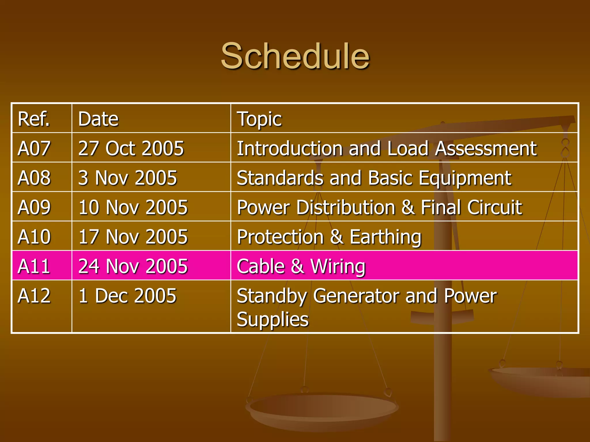
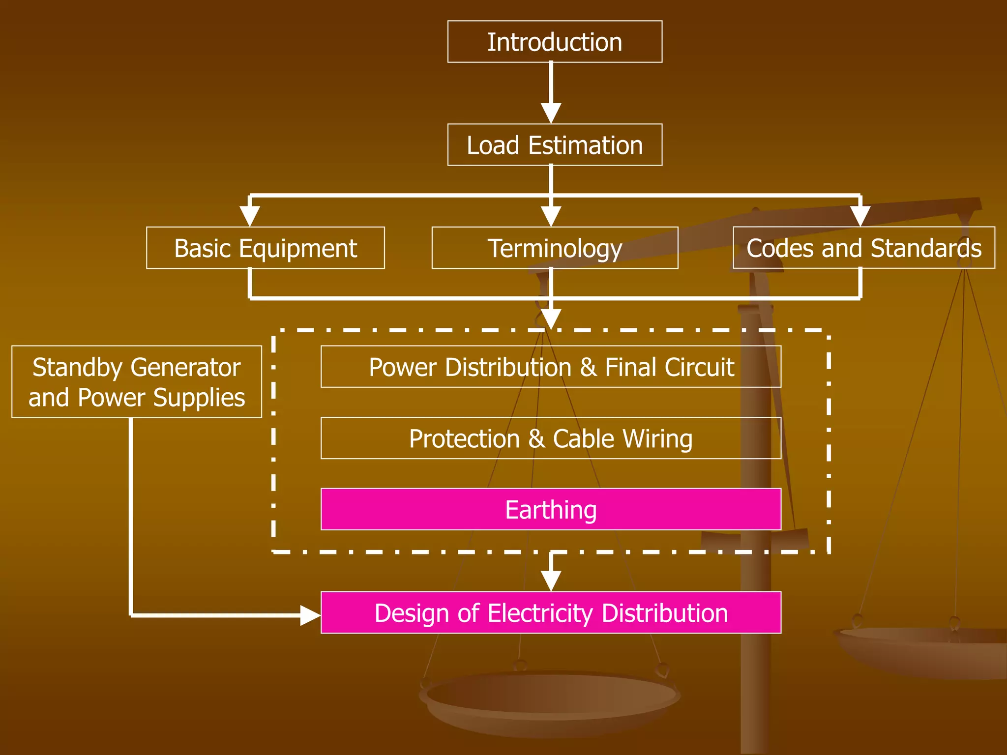
(PRIYA) Rajgurunagar Call Girls Just Call 7001035870 [ Cash on Delivery ] Pun...
cable sizing.ppt
1. Schedule
Ref. Date Topic
A07 27 Oct 2005 Introduction and Load Assessment
A08 3 Nov 2005 Standards and Basic Equipment
A09 10 Nov 2005 Power Distribution & Final Circuit
A10 17 Nov 2005 Protection & Earthing
A11 24 Nov 2005 Cable & Wiring
A12 1 Dec 2005 Standby Generator and Power
Supplies
3. Earthing and Design of
Electricity Distribution
Date : 24 November 2005
Module Code : A11
Ir. KF Cheung
4. Earthed Equipotential Bonding and
Automatic Disconnection
C) Determination of Disconnection Time
1) Maximum values of earth loop impedance for various
overcurrent protective devices are shown in table 41B1,
Table 41B2 & Table 41D
2) Actual earth loop impedance can be calculated as follows:
Zs = Ze + Z1 + Z2
Ze : Earth loop impedance at the source
Z1 : Impedance of phase conductor
Z2 : Impedance of circuit protective conductor (cpc)
5. Earthed Equipotential Bonding and
Automatic Disconnection
C) Determination of Disconnection Time
3) Compare the actual Zs with the tabulated Zs(max):
The actual Zs value measured from the installation should be
smaller than the Zs(max) value from IEE Tables in order to achieve
safe disconnection time. Attention is drawn on that the Zs (max)
form IEE Tables shall be converted to nominal supply voltage
system in Hong Kong before comparison.
Zs (max :220) = Zs (max : 240) in IEE Tables X 220/240
6. Earthed Equipotential Bonding and
Automatic Disconnection
C) Determination of Disconnection Time
4) The earth fault current can be calculated using the
following formula:
If = Uo /Zs
Uo = Phase to earth voltage
If = earth fault current
5) By putting the calculated fault current against the
characteristic curves of the protective device given in IEE,
the actual disconnection time can be found.
7. Example
A 220V circuit is protected by a 30A Type 2 MCB, the
cable used is 2.5/1.5 twin with cpc PVC copper conductor,
if the circuit length is 15m and Ze up to the MCB board
is 0.5Ω, what is the actual disconnection time?
From table 17, R1+R2 /m = 19.51mΩ x 1.38
= 0.269 Ω/m
9. A) Cable Selection
Factors to be considered in sizing of cable conductors
Conductor material
Insulating material
Method of installation
Installed environment
Ambient temperature
Thermal insulating enclosure
Adjacent cables
Type of protective device
Voltage drop
Minimum cross-sectional area
10. Comparison between Copper
Conductor and Aluminum Conductor
A) Copper Conductor
High degree of electrical conductivity
Tough, slow to tarnish
Can be jointed without any special provision to prevent electrolytic
action
B) Aluminum Conductor
Lower price & light in weight
Pliable, it can be used in solid-core cables
Excellent resistance to corrosion
12. Bends of Non-flexible Cable
The minimum internal radius bend in cables for fixing
wiring are shown in the following table
13. Correction Factor for Conductors
Factors which affect the ability of a cable to lose heat are:
Grouping (Cg or C1)
Ambient temperature (Ca or C2)
Thermal insulation (Ci or C3)
Semi-enclosed fuse to BS 3036 (0.725 or C4)
Type of installation (Table 4A)
14. Correction Factor for Conductors
A) Grouping factor (Cg) - 1
IEE Table 4B1 gives correction factors to be applied to te tabulated
current-carrying capacities where cables or circuits are grouped.
Where the horizontal clearance s between adjacent cables exceed
two cable diameter (2D2), no correction factor need be applied.
15. Correction Factor for Conductors
A) Grouping factor (Cg) - 2
If a cable is expected to carry not more than 30% of its grouped
rating, it may be ignored from the rest of the group.
16. Correction Factor for Conductors
B) Correction Factor for Ambient Temperature (Ca)
Correction factor for ambient temperature is shown in IEE Table
4C1. Where for semi-enclosed fuses are being used, see IEE Table
4C2.
It ≥ In / Ca
Typical data are shown in the following table for quick reference.
17. Correction Factor for Conductors
C) Correction Factor for thermal Insulation (Ci)
The value of current-carrying-capacity for various sizes of
conductors shown in Tables of Appendix 4 have been taken into
account of cables installed in a thermally insulated wall or ceiling
where one side of the cable is in contact with a thermally
conductive surface.
Where the cable is totally enclosed in thermal insulation, Ci=0.5
shall be used in absence of more precise information.
It ≥ In / Ci
Ci shall only be applied to the ‘open and clipped direct’ column of
respective IEE Tables.
18. Correction Factor for Conductors
D) factor for Semi-enlosed fuse to BS3036 (C4)
When semi-enclosed fuse is used for protecting the conductor, a
derating factor of 0.726 shall be applied.
19. Correction Factor for Conductors
E) General Formula for Correction Factors Applied to Cable
Sizing
It ≥ In / Cg x Ca x Ci x C4
21. Example
Protective device : BS 3036 fuses
Ambient temperature: 30oC
Cable use :PVC twin with cpc cable
Cabling conditions at:
1) Bunched and clipped direct
2) Passed through totally enclosed thermal insulation area
3) One side in contact with thermally insulated ceiling
4) Passed through a boiler house where ambient temperature of
45oC
5) Clipped direct
Ignore voltage drop
What cable sizes are required?
22. Voltage Drop
The overall voltage drop shall not exceed the value
appropriate to the safe functioning of the equipment in
normal service.
The voltage drop in any circuit from the origin of
installation to the current-using equipment should not
exceed 4% of the nominal voltage.
Volt drop pre unit value in from of mv/A/m are shown on
IEE tables of Appendix 4. The values are based on the
circuit conductor working at the maximum permitted
operating temperature and at unity power factor.
26. Voltage Drop
Voltage drop (V.D.) can be calculated as follows:
V.D. = design current (Ib) x circuit length (L) x volt drop
per unit (mv/A/m)
27. Example
A PVC/SWA/PVC armoured cable is to be installed from an
HRC 100A fuse in a distribution board to a 3-phase 380V
motor, along with 5 other cables fixed to a perforated
metal cable tray where the cable sheaths will be touching,
if the cable length is 100 meters and the power factor of
the load is 0.866, what size of cable would be required to
satisfy voltage drop if the ambient temperature is 30oC
and the voltage drop in the 3 phase feeder cable up to the
distribution board is 7.7V and the total voltage drop
allowed is 4%?
28. Sizing Circuit Protective Conductors
If the conductor ≤ 35mm2 : Zs = Ze + R1 + R2
>35mm2 : Zs = Ze + Z1 + Z2
Use the formula : S ≥ √{(I2t)} / K
Value of K : from IEE Tables 54B to 54F
If = Uo / Zs
Value of t from IEE Fig. 1 to 8 of Appendix 3
Use Table 54G to size the minimum size of protective
conductors.
29. Thermal Constraint
To protect conductor insulation against thermal damage
during short circuit conditions.
I2 t = K2 S2
t = K2 S2/ I2
t = duration in second
S = cross-sectional area in mm2
I = effective short-circuit current in A
K = 115 for copper conductor insulated with PVC
30. Thermal Constraint
Procedure
To check the prospective short-circuit current at the
farthest point of the circuit from the point where the
device is installed
To check the operation time of the device according to the
short-circuit current from the time/ current characteristic
of the device
To check the adiabatic line of the conductor by
superimposing onto the characteristics of protective
devices.
31. Cable Selection Procedure
Select wiring system to be installed and type of cable
Calculate the equipment current demand using Table 4A
(15 Edition)
Calculate the circuit design current (Ib) and using diversity
allowance.
Determine the overcueent protective device (In) : type;
rating
Check Ib ≤ In
Determine correction factors for installation
Grouping (Cg)
Ambient temperature (Ca)
Thermal insulation (Ci)
Semi-enclosed fuse (C4)
32. Cable Selection Procedure
Calculate the tabulated current carrying capacity of
conductor:
It (min) ≥ In x (1/ Cg) x (1/ Ca) x (1/ Ci) x (1/ C4)
Select cable size from Appendix 4
Check Ib ≤ In ≤ Iz
Calculate volt drop at the farthest point of circuit
33. Cable Selection Procedure
Dose device offer shock protection in accordance with
table 41B1, 41B2 & 41D for Zs (max)?
Check Zs ≤ Zs (max) from the tables
If No :
Re-select device or re-select phase conductor size
Re-select cpc size
Use alternative method as stated in Reg. 413-02-12
Checked by calculation
Obtain Ze form supply authority
Calculate R1 + R2 using Table 17A & B
Determine actual Zs = Ze + (R1 + R2)
34. Cable Selection Procedure
Dose the type and size of cpc offer protection?
Check : S ≥ √{(I2t)} / K
If No : re-select type and/ or size of cpc
Check the adiabatic line of conductor against the
characteristic of overcurrent protective device.
35. B1) Type of Conduit
B2) Sizing of Conduit
B3) Type of Trunking
B4) Sizing of Trunking
B5) Ducting
B6) Segregation of Circuit
B) Conduit & Trunking
36. Steel Conduit to BS 4568 : Part 1
A) Light duty type: plain and conduits
Limited to use in dry situation;
Unsuitable for bending
Low degree of mechanical protection
B) Heavy duty type: screwed-end conduits
Back enamel for internal use in dry situation;
Hot-dip galvanized for external use in situation
subject to dampness or water condensation;
Good mechanical strength and electrical continuity.
B1) Type of Conduit
37. B1) Type of Conduit
Steel Conduit to BS 4568 : Part 1
C) Classification for protection:
Class Protection Applied Example
1 Light protection both inside & outside Priming paint
2 Medium protection both inside &
outside
Stoved enamel;
Air-drying paint
3 Medium heavy protection : inside as
Class 2;
Outside as Class 4
Stoved enamel inside;
Sherardized outside
4 Heavy protection both inside &
outside
Hot-dip zinc coating,
sherardizing
38. Steel Conduit to BS 4568 : Part 1
D) Heavy duty hot-dip galvanized steel
conduit system is the most common use
system for surface conduit wiring and
concealed conduit wiring. Conduit is
supplied in standard lengths of 4 meters
and is manufactured in accordance with
BS4568.
B1) Type of Conduit
39. Plastic conduits
To BS4607 Part 1 and 2;
Characteristics : light, easily bend, less
installation time, no water condensation,
lower cost;
Heavy duty PVC conduits can be
concealed but CPC are required.
B1) Type of Conduit
40. Copper Conduits
High resistance to corrosion;
Last for long time;
Higher cost;
Act as excellent circuit protective
conductor (CPC)
B1) Type of Conduit
41. Aluminum Conduits
Light weight and lower cost;
Not so good in mechanical protection
Flexible Conduits
To BS731 : Part 1
Used for final connection to machinery;
CPC are required.
B1) Type of Conduit
42. B2) Sizing of Conduit
IEE Regulation (15th Edition) provide the
following tables for ease of conduit sizing:
Table A, B for 1/C PVC cables in a straight run ≤ 3m;
Table C, D for 1/C PVC cable in conduit run > 3m.
The conduit size is considered satisfactory if the
conduit factor is equal to or exceeds the sum of
the cable factors
43. B2) Sizing of Conduit
Type of Conductor C.S.A. of Conductor (mm2) Factor
Solid 1
1.5
2.5
22
27
39
Stranded 1.5
2.5
4
6
10
31
43
58
68
146
Table A – Cable factors for short straight runs
44. B2) Sizing of Conduit
Conduit Diameter (mm) Factor
16 290
20 460
25 800
32 1400
Table B – Conduit factors for short straight runs
45. B2) Sizing of Conduit
Type of Conductor C.S.A. of Conductor
(mm2)
Factor
Solid or Stranded 1 16
1.5 22
2.5 30
4 41
6 58
10 105
Table C – Cable factors for long straight runs, or runs incorporating bends
46. B2) Sizing of Conduit
Table D – Conduit factors for runs incorporating bends
Refer to
Table A and B
47. B2)Sizing of Conduit
Example
In a conduit installation the length of run is 10m,
assuming 2 right-angle bend. What is the
conduit size to enclose four 2.5 mm2 PVC cables?
From Table C, factor for one 2.5mm2 cable = 30
Therefore, four 2.5mm2 cables = 4 x 30 = 120
From Table D, suitable conduit size with a factor of
141(>120) is 20mm.
[10m Vs 2 bends, cable factor : 141]
48. B3)Type of Trunking
Use in conditions where a considerable no. of
cables are required in an installation or where
cables are too large for drawing into conduits.
Erection time is reduced (wiring is easier and
quicker)
Multi-compartment trunking provides circuit
segregation.
49. B3)Type of Trunking
Typical types of trunking
A) Steel trunking for busbar rising mains.
B) PVC skirting 3-compartment trunking for fitting-out
wiring works where different category circuits such as
Telephone cable, CABDS cable & power supply cable are
to be installed in same run.
C) Floor trunking to BS 4678 : Part 2 provides cabling to
service boxes flushed with floor level (e.g. in open-plan
office or dental room)
D) Tap-on trunking in factory for internal power supply
to machinery by plugging into the overhead trunking.
E) Steel surface trunking for cable to BS 4678 : Part 1
50. B3)Type of Trunking
Classification for protection against corrosion:
Class 1 Electroplated zinc having a minimum thickness
of zinc coating of 0.0012mm, inside and outside.
Class 2 As Class 1 but additional coating of stoved or air
drying paint, applied at least to the external
surface.
Class 3 Hot dip zinc coated steel.
51. B4) Sizing of Trunking
Type of Conductor C.S.A of Conductor (mm2) Factor
Solid 1.5
2.5
7.1
10.2
Stranded 1.5
2.5
4
6
10
8.1
11.4
15.2
22.9
36.3
Table E – Cable factors for trunking
52. B4) Sizing of Trunking
Dimension of Trunking (mm x mm) Factor
50 x 37.5 767
50 x 50 1037
75 x 25 738
75 x 37.5 1145
75 x 50 1555
75 x 75 2371
100 x 25 993
100 x 37.5 1542
100 x 50 2091
100 x 75 3189
100 x 100 4252
Table F –Factors for trunking
53. B4) Sizing of Trunking
Example
What is the maximum no. of 10mm2 PVC cables
permitted in 50mm x 50mm trunking?
From Table E, factor of 10mm2 conductor = 36.3
From Table F, factor of 50 x 50mm trunking = 1037
Maximum no. of cable= 1037 ÷ 36.3
= 28.56 (say 28)
54. B5) Ducting
It provided mechanical protection for cable run
in the ground or under concreted floor.
Types of ducting:
Concrete ducts
Steel underfloor ducts
Fibre underfloor ducts
Maximum spacing factor is 35%.
It should be securely fixed and protected against
corrosion and mechanical damage.
55. B5) Ducting
Entries to duct must be protected against the
inflow of water.
Cables installed in underground ducts shall have
a metal sheath.
Underfloor trunking should be fabricated with
sheet steel of not less than 12mm thickness for
compartment width up to 100mm, but at least
1.6mm thickness for compartment width over
100mm. The minimum thickness of 1mm shall
be used for the partitions and connector
material.
56. B6) Segregation of Circuits
1) Suitable segregation between enclosed circuits with different
categories shall be provided in wiring. For example, a low voltage
circuit shall be separated from an extra-low voltage circuit.
2) Types of Circuit:
Category 1 Circuit A circuit (other than a fire alarm or emergency
lighting circuit) operation at low voltage and
supplied directly from a main supply system
Category 2 Circuit With the exception of firm alarm and emergency
lighting circuits, ant circuit for telecommunication
(e.g. radio, telephone…) which is supplied form a
safety source.
Category 3 Circuit A fire alarm circuit or an emergency lighting
circuit.
Category 4 Circuit A high voltage circuit.
57. B6) Segregation of Circuits
3) Low Voltage circuit shall be segregated form extra-low voltage
circuit. Extra-low voltage cables shall not be drawn into the same
conduit or duct, or terminated in the same box or block as low
voltage cables unless the former are insulated for the highest
voltage present in the low voltage circuit.
4) Cables of fire alarm and emergency lighting circuits shall not in
any circumstances be drawn into the same conduit duct or ducting
of other cables.
58. B6) Segregation of Circuits
5) Electrical services shall not be installed with pipes or tubes of
non-electrical services (e.g. air, gas, oil, or water) in the same
conduit, ducting or trunking. This requirement does not apply where
the various services are under common supervision and it is
confirmed that no mutual detrimental influence can occur.
6) For cables of category 1,2,3 circuits that are installed without
enclosure or underground, a minimum separation of 50mm should
be provided between different category circuits or alternatively at
least 25mm separation with slabs of concrete inserted between the
circuits and the shortest path round the concrete should exceed
75mm.
59. B6) Segregation of Circuits
7) Insulated bridge of at least 6mm thick should be used for
separation of surface wiring of Category 1,2,3 circuit running across
each other. The bridge should overlap the cables by at least 25mm
on either side of point of crossing.
8) For cables of Category 4 circuit that are installed without
enclosure or underground, a minimum separation of 300mm should
be provided between Categories or alternatively a reduced
separation with 50mm thick slabs of concrete inserted between the
circuits and the shortest path round the concrete should exceed
180mm.
60. Example
Descriptions:
A flat of about 90m2 (useable area), with three bedrooms, (the master
bedroom with en-suite bathroom), a guest bathroom, a kitchen, a
dining room, lounge (living room) and a store room.
An air-conditioner (<1.5 h.p., i.e. < 15A input current) is expected to be
in each bedroom.
An large air-conditioner (may be >2 h.p., i.e. >=15A input current) is
expected to be in the dining room, and it also for the lounge.
An electric cooker of about 14A rating is expected to be installed in the
kitchen.
Hot water is provided by gas heaters in bathrooms and the kitchen
Battery operated door bell and clocks are expected.
63. Example
To provision here is more than that of the
minimum recommended requirements in the CP
for WR.
No socket outlet is provided in the bathrooms,
and the switches for lighting and the ventilation
fan should be installed outside the bathrooms.
66. Typical Earthing Systems - 1
TT system
A system having one point of the source of energy
directly earthed, the exposed-conductive parts of the
installation being connected to earth electrodes
electrically independent of the earth electrodes of the
source.
67. Typical Earthing Systems - 2
TN-S system
A system having one point of the source of energy directly
earthed and having separate neutral and protective conductors
throughout the system.
68. Typical Earthing Systems - 3
TNC-S system
A system having one point of the source of energy directly
earthed, the neutral and protective functions are combined in a
single conductor in part of the system.
69. Type of Earth Electrode
The following Earth Electrode
Deep driven earth rods and/ or parallel driven earth
rods
Buried tapes/ plated
Welded metal reinforcement of concrete