Download as PDF, PPTX


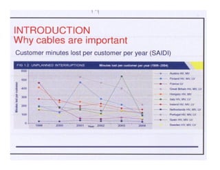
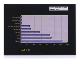

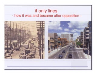

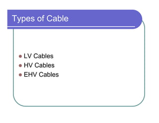

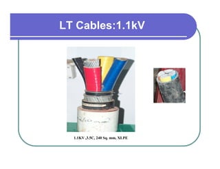
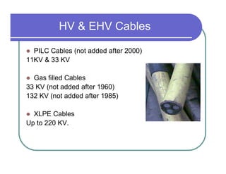


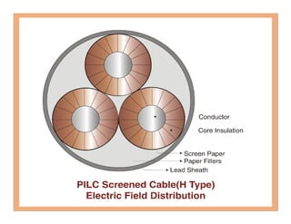
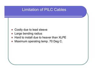

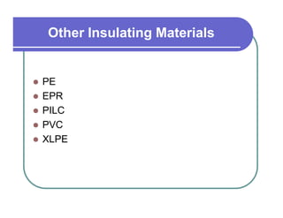

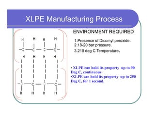
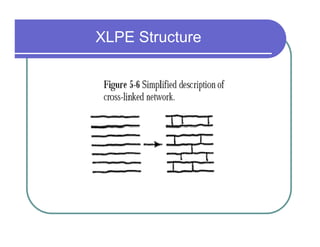
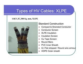


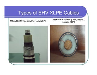


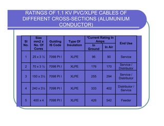
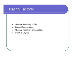


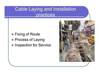


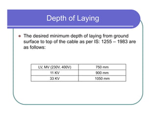


The document discusses power cable technology, including: 1) The importance of cables for reliable power distribution and aesthetic reasons with growing load density. 2) The construction of different voltage cables, from LV to EHV, using materials like XLPE, PILC, and gas insulation. 3) Factors that determine cable ratings like soil conditions, depth of laying, and allowable operating temperature. 4) Best practices for cable laying including fixing routes, trenching, laying procedures, and post-laying inspections.


