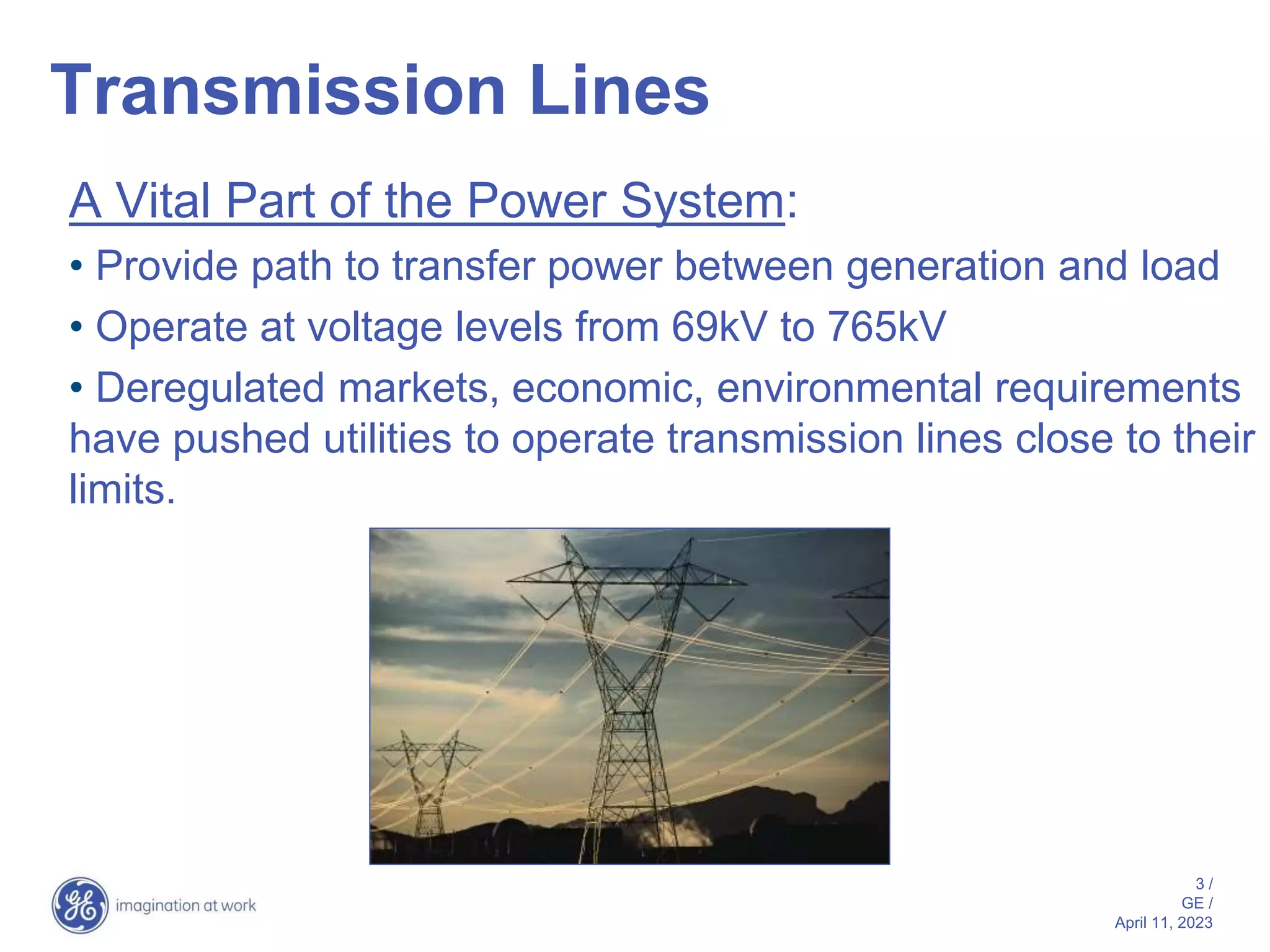
This document provides an overview of fundamentals of distance protection for transmission lines. It discusses types of transmission lines and typical protection schemes used based on line length. It then describes what distance protection is and challenges in relay design related to transients. The document outlines considerations for distance relay characteristics, polarization, and schemes including non-pilot and pilot schemes. It discusses redundancy, security, out-of-step relaying and series compensation.
Tutorial on Distance and Over Current ProtectionSARAVANAN A
Contents
• Protection Philosophy of ERPC
• Computation of Distance Relay Setting
• System Study to Understand Distance Relay
Behaviour
• DOC and DEF for EHV system
Tutorial on Distance and Over Current ProtectionSARAVANAN A
Contents
• Protection Philosophy of ERPC
• Computation of Distance Relay Setting
• System Study to Understand Distance Relay
Behaviour
• DOC and DEF for EHV system
How is power transformer protected??? This provides a basic understanding of power transformer. Furthermore, the protective relay application on power transformer is included.
Bus Bar protection Schemes,Simple Current differential scheme,Need for bus bar protection,requirement of bus bar protection,recommendations for providing bus bar protection,basics of busbar protection,Types of bus-bar protections,High speed differential protection
To sense/detect the fault occurrence and other abnormal conditions at the protected equipment/area/section.
To operate the correct circuit breakers so as to disconnect only the faulty equipment/area/section as quickly as possible, thus minimizing the damage caused by the faults.
To operate the correct circuit breakers to isolate the faulty equipment/area/section from the healthy system in the case of abnormalities like overloads, unbalance, undervoltage, etc.
To clear the fault before the system becomes unstable.
To identify distinctly where the fault has occurred.
Protection of transmission lines (distance)Rohini Haridas
This gives idea about necessity of protection of transmission line and protection based on time grading as well as on current grading. Also includes three step distance protection of transmission line
Practical handbook-for-relay-protection-engineersSARAVANAN A
The ‘Hand Book’ covers the Code of Practice in Protection Circuitry including standard lead and device numbers, mode of connections at terminal strips, colour codes in multicore cables, Dos and Donts in execution. Also, principles of various protective relays and schemes including special protection schemes like differential,
restricted, directional and distance relays are explained with sketches. The norms of protection of generators, transformers, lines & Capacitor Banks are also given.
�The sample calculations shown here illustrate steps involved in calculating the relay settings for generator protection.
�Other methodologies and techniques may be applied to calculate relay settings based on specific applications.
Performance of quadrilateral relay on EHV transmission line protection during...IDES Editor
Distance relays have many characteristics
such as Impedance, lenticular, Offset Mho, Mho and
Quadrilateral characteristics. Quadrilateral
characteristics provide highly suitable protection for
Transmission line as compared to other characteristics.
Quadrilateral relay provides flexible protection during
high fault resistance of ground and phase faults. This is
advantageous for protection of phase-to-earth faults on
short lines, lines without earth wires, non-effectively
earthed systems and feeders with extremely high tower
footing resistance. This also provides fault impedance
coverage for both phase to phase and phase to ground
faults without effecting load encroachment. I explained
factors impacting performance of Quadrilateral relay
focusing on accuracy and speed of operation. In this
paper Quadrilateral relay system and Bergeron model
type transmission line are designed and simulated using
PSCAD/EMTDC analysis software to study the different
type of fault at various fault resistances. A Fast Fourier
technique is used to generate apparent impedance. The
simulation result shows Quadrilateral relay are highly
suitable for protection of extra high voltage transmission
line during resistance faults. This scheme improves the
sensitivity, and reliability.
Need for protection
Nature and causes of faults
Types of faults
Fault current calculation using symmetrical components
Zones of protection
Primary and back up protection
Essential qualities of protection
Typical protection schemes.
Power Swing Phenomena and Comparative Study of Its Detection on Transmission ...ijsrd.com
Power systems are subject to a wide range of small or large disturbances during operating conditions. Small changes in loading conditions occur continually. The power system must adjust to these changing conditions and continue to operate satisfactorily and within the desired limits of voltage and frequency. The power system should be designed to survive larger types of disturbances, such as faults, loss of a large generator, or line switching. Certain system disturbances may cause loss of synchronism between a generator and rest of the utility system, or between interconnected power systems of neighboring utilities. If such a loss of synchronism occurs, it is imperative that the generator or system areas operating asynchronously are separated immediately to avoid widespread outages and equipment damage. Here it is described to distinguish between power swing and real fault. It is also discussed recent enhancements in the design of out of step tripping and blocking protection functions that improve the security and reliability of the power system. In addition to that the behavior of distance relay element during power swing and during fault is simulated using MATLAB and SIMULINK simulations.
Water scarcity is the lack of fresh water resources to meet the standard water demand. There are two type of water scarcity. One is physical. The other is economic water scarcity.
Sachpazis:Terzaghi Bearing Capacity Estimation in simple terms with Calculati...Dr.Costas Sachpazis
Terzaghi's soil bearing capacity theory, developed by Karl Terzaghi, is a fundamental principle in geotechnical engineering used to determine the bearing capacity of shallow foundations. This theory provides a method to calculate the ultimate bearing capacity of soil, which is the maximum load per unit area that the soil can support without undergoing shear failure. The Calculation HTML Code included.
TECHNICAL TRAINING MANUAL GENERAL FAMILIARIZATION COURSEDuvanRamosGarzon1
AIRCRAFT GENERAL
The Single Aisle is the most advanced family aircraft in service today, with fly-by-wire flight controls.
The A318, A319, A320 and A321 are twin-engine subsonic medium range aircraft.
The family offers a choice of engines
Hybrid optimization of pumped hydro system and solar- Engr. Abdul-Azeez.pdffxintegritypublishin
Advancements in technology unveil a myriad of electrical and electronic breakthroughs geared towards efficiently harnessing limited resources to meet human energy demands. The optimization of hybrid solar PV panels and pumped hydro energy supply systems plays a pivotal role in utilizing natural resources effectively. This initiative not only benefits humanity but also fosters environmental sustainability. The study investigated the design optimization of these hybrid systems, focusing on understanding solar radiation patterns, identifying geographical influences on solar radiation, formulating a mathematical model for system optimization, and determining the optimal configuration of PV panels and pumped hydro storage. Through a comparative analysis approach and eight weeks of data collection, the study addressed key research questions related to solar radiation patterns and optimal system design. The findings highlighted regions with heightened solar radiation levels, showcasing substantial potential for power generation and emphasizing the system's efficiency. Optimizing system design significantly boosted power generation, promoted renewable energy utilization, and enhanced energy storage capacity. The study underscored the benefits of optimizing hybrid solar PV panels and pumped hydro energy supply systems for sustainable energy usage. Optimizing the design of solar PV panels and pumped hydro energy supply systems as examined across diverse climatic conditions in a developing country, not only enhances power generation but also improves the integration of renewable energy sources and boosts energy storage capacities, particularly beneficial for less economically prosperous regions. Additionally, the study provides valuable insights for advancing energy research in economically viable areas. Recommendations included conducting site-specific assessments, utilizing advanced modeling tools, implementing regular maintenance protocols, and enhancing communication among system components.
NO1 Uk best vashikaran specialist in delhi vashikaran baba near me online vas...Amil Baba Dawood bangali
Contact with Dawood Bhai Just call on +92322-6382012 and we'll help you. We'll solve all your problems within 12 to 24 hours and with 101% guarantee and with astrology systematic. If you want to take any personal or professional advice then also you can call us on +92322-6382012 , ONLINE LOVE PROBLEM & Other all types of Daily Life Problem's.Then CALL or WHATSAPP us on +92322-6382012 and Get all these problems solutions here by Amil Baba DAWOOD BANGALI
#vashikaranspecialist #astrologer #palmistry #amliyaat #taweez #manpasandshadi #horoscope #spiritual #lovelife #lovespell #marriagespell#aamilbabainpakistan #amilbabainkarachi #powerfullblackmagicspell #kalajadumantarspecialist #realamilbaba #AmilbabainPakistan #astrologerincanada #astrologerindubai #lovespellsmaster #kalajaduspecialist #lovespellsthatwork #aamilbabainlahore#blackmagicformarriage #aamilbaba #kalajadu #kalailam #taweez #wazifaexpert #jadumantar #vashikaranspecialist #astrologer #palmistry #amliyaat #taweez #manpasandshadi #horoscope #spiritual #lovelife #lovespell #marriagespell#aamilbabainpakistan #amilbabainkarachi #powerfullblackmagicspell #kalajadumantarspecialist #realamilbaba #AmilbabainPakistan #astrologerincanada #astrologerindubai #lovespellsmaster #kalajaduspecialist #lovespellsthatwork #aamilbabainlahore #blackmagicforlove #blackmagicformarriage #aamilbaba #kalajadu #kalailam #taweez #wazifaexpert #jadumantar #vashikaranspecialist #astrologer #palmistry #amliyaat #taweez #manpasandshadi #horoscope #spiritual #lovelife #lovespell #marriagespell#aamilbabainpakistan #amilbabainkarachi #powerfullblackmagicspell #kalajadumantarspecialist #realamilbaba #AmilbabainPakistan #astrologerincanada #astrologerindubai #lovespellsmaster #kalajaduspecialist #lovespellsthatwork #aamilbabainlahore #Amilbabainuk #amilbabainspain #amilbabaindubai #Amilbabainnorway #amilbabainkrachi #amilbabainlahore #amilbabaingujranwalan #amilbabainislamabad
Democratizing Fuzzing at Scale by Abhishek Aryaabh.arya
Presented at NUS: Fuzzing and Software Security Summer School 2024
This keynote talks about the democratization of fuzzing at scale, highlighting the collaboration between open source communities, academia, and industry to advance the field of fuzzing. It delves into the history of fuzzing, the development of scalable fuzzing platforms, and the empowerment of community-driven research. The talk will further discuss recent advancements leveraging AI/ML and offer insights into the future evolution of the fuzzing landscape.
Saudi Arabia stands as a titan in the global energy landscape, renowned for its abundant oil and gas resources. It's the largest exporter of petroleum and holds some of the world's most significant reserves. Let's delve into the top 10 oil and gas projects shaping Saudi Arabia's energy future in 2024.
Automobile Management System Project Report.pdfKamal Acharya
The proposed project is developed to manage the automobile in the automobile dealer company. The main module in this project is login, automobile management, customer management, sales, complaints and reports. The first module is the login. The automobile showroom owner should login to the project for usage. The username and password are verified and if it is correct, next form opens. If the username and password are not correct, it shows the error message.
When a customer search for a automobile, if the automobile is available, they will be taken to a page that shows the details of the automobile including automobile name, automobile ID, quantity, price etc. “Automobile Management System” is useful for maintaining automobiles, customers effectively and hence helps for establishing good relation between customer and automobile organization. It contains various customized modules for effectively maintaining automobiles and stock information accurately and safely.
When the automobile is sold to the customer, stock will be reduced automatically. When a new purchase is made, stock will be increased automatically. While selecting automobiles for sale, the proposed software will automatically check for total number of available stock of that particular item, if the total stock of that particular item is less than 5, software will notify the user to purchase the particular item.
Also when the user tries to sale items which are not in stock, the system will prompt the user that the stock is not enough. Customers of this system can search for a automobile; can purchase a automobile easily by selecting fast. On the other hand the stock of automobiles can be maintained perfectly by the automobile shop manager overcoming the drawbacks of existing system.
About
Indigenized remote control interface card suitable for MAFI system CCR equipment. Compatible for IDM8000 CCR. Backplane mounted serial and TCP/Ethernet communication module for CCR remote access. IDM 8000 CCR remote control on serial and TCP protocol.
• Remote control: Parallel or serial interface.
• Compatible with MAFI CCR system.
• Compatible with IDM8000 CCR.
• Compatible with Backplane mount serial communication.
• Compatible with commercial and Defence aviation CCR system.
• Remote control system for accessing CCR and allied system over serial or TCP.
• Indigenized local Support/presence in India.
• Easy in configuration using DIP switches.
Technical Specifications
Indigenized remote control interface card suitable for MAFI system CCR equipment. Compatible for IDM8000 CCR. Backplane mounted serial and TCP/Ethernet communication module for CCR remote access. IDM 8000 CCR remote control on serial and TCP protocol.
Key Features
Indigenized remote control interface card suitable for MAFI system CCR equipment. Compatible for IDM8000 CCR. Backplane mounted serial and TCP/Ethernet communication module for CCR remote access. IDM 8000 CCR remote control on serial and TCP protocol.
• Remote control: Parallel or serial interface
• Compatible with MAFI CCR system
• Copatiable with IDM8000 CCR
• Compatible with Backplane mount serial communication.
• Compatible with commercial and Defence aviation CCR system.
• Remote control system for accessing CCR and allied system over serial or TCP.
• Indigenized local Support/presence in India.
Application
• Remote control: Parallel or serial interface.
• Compatible with MAFI CCR system.
• Compatible with IDM8000 CCR.
• Compatible with Backplane mount serial communication.
• Compatible with commercial and Defence aviation CCR system.
• Remote control system for accessing CCR and allied system over serial or TCP.
• Indigenized local Support/presence in India.
• Easy in configuration using DIP switches.
COLLEGE BUS MANAGEMENT SYSTEM PROJECT REPORT.pdfKamal Acharya
The College Bus Management system is completely developed by Visual Basic .NET Version. The application is connect with most secured database language MS SQL Server. The application is develop by using best combination of front-end and back-end languages. The application is totally design like flat user interface. This flat user interface is more attractive user interface in 2017. The application is gives more important to the system functionality. The application is to manage the student’s details, driver’s details, bus details, bus route details, bus fees details and more. The application has only one unit for admin. The admin can manage the entire application. The admin can login into the application by using username and password of the admin. The application is develop for big and small colleges. It is more user friendly for non-computer person. Even they can easily learn how to manage the application within hours. The application is more secure by the admin. The system will give an effective output for the VB.Net and SQL Server given as input to the system. The compiled java program given as input to the system, after scanning the program will generate different reports. The application generates the report for users. The admin can view and download the report of the data. The application deliver the excel format reports. Because, excel formatted reports is very easy to understand the income and expense of the college bus. This application is mainly develop for windows operating system users. In 2017, 73% of people enterprises are using windows operating system. So the application will easily install for all the windows operating system users. The application-developed size is very low. The application consumes very low space in disk. Therefore, the user can allocate very minimum local disk space for this application.
2. 2 /
GE /
April 11, 2023
Outline
• Transmission line introduction
• What is distance protection?
• Non-pilot and pilot schemes
• Redundancy considerations
• Security for dual-breaker terminals
• Out-of-step relaying
• Single-pole tripping
• Series-compensated lines
3. 3 /
GE /
April 11, 2023
Transmission Lines
A Vital Part of the Power System:
• Provide path to transfer power between generation and load
• Operate at voltage levels from 69kV to 765kV
• Deregulated markets, economic, environmental requirements
have pushed utilities to operate transmission lines close to their
limits.
4. 4 /
GE /
April 11, 2023
Transmission Lines
Classification of line length depends on:
Source-to-line Impedance Ratio (SIR),
and
Nominal voltage
Length considerations:
Short Lines: SIR > 4
Medium Lines: 0.5 < SIR < 4
Long Lines: SIR < 0.5
5. 5 /
GE /
April 11, 2023
Typical Protection Schemes
Short Lines
• Current differential
• Phase comparison
• Permissive Overreach Transfer Trip (POTT)
• Directional Comparison Blocking (DCB)
6. 6 /
GE /
April 11, 2023
Typical Protection Schemes
Medium Lines
• Phase comparison
• Directional Comparison Blocking (DCB)
• Permissive Underreach Transfer Trip (PUTT)
• Permissive Overreach Transfer Trip (POTT)
• Unblocking
• Step Distance
• Step or coordinated overcurrent
• Inverse time overcurrent
• Current Differential
7. 7 /
GE /
April 11, 2023
Typical Protection Schemes
Long Lines
• Phase comparison
• Directional Comparison Blocking (DCB)
• Permissive Underreach Transfer Trip (PUTT)
• Permissive Overreach Transfer Trip (POTT)
• Unblocking
• Step Distance
• Step or coordinated overcurrent
• Current Differential
8. 8 /
GE /
April 11, 2023
What is distance protection?
For internal faults:
> IZ – V and V approximately
in phase (mho)
> IZ – V and IZ
approximately in phase
(reactance)
RELAY (V,I)
Intended
REACH point
Z
F1
I*Z
V=I*ZF
I*Z - V
9. 9 /
GE /
April 11, 2023
What is distance protection?
For external faults:
> IZ – V and V approximately
out of phase (mho)
> IZ – V and IZ
approximately out of phase
(reactance)
RELAY (V,I)
Intended
REACH point
Z I*Z
V=I*ZF
I*Z - V
F2
10. 10 /
GE /
April 11, 2023
What is distance protection?
RELAY
Intended
REACH point
Z
11. 11 /
GE /
April 11, 2023
Source Impedance Ratio,
Accuracy & Speed
Lin
e
System
Relay
Voltage at the relay:
SIR
f
f
V
V
PU
LOC
PU
LOC
N
R
]
[
]
[
Consider SIR = 0.1
Fault location Voltage
(%)
Voltage change
(%)
75% 88.24 2.76
90% 90.00 0.91
100% 90.91 N/A
110% 91.67 0.76
12. 12 /
GE /
April 11, 2023
Source Impedance Ratio,
Accuracy & Speed
Lin
e
System
Relay
Voltage at the relay:
SIR
f
f
V
V
PU
LOC
PU
LOC
N
R
]
[
]
[
Consider SIR = 30
Fault location Voltage
(%)
Voltage change
(%)
75% 2.4390 0.7868
90% 2.9126 0.3132
100% 3.2258 N/A
110% 3.5370 0.3112
13. 13 /
GE /
April 11, 2023
Challenges in relay design
> Transients:
– High frequency
– DC offset in currents
– CVT transients in
voltages
CVT output
0 1 2 3 4
steady-state
output
power cycles
-30
-20
-10
0
10
20
30
voltage,
V
C1
C2
2
3 5
6
1
4
7
High Voltage Line
Secondary
Voltage
Output
8
14. 14 /
GE /
April 11, 2023
Challenges in relay design
> Transients:
– High frequency
– DC offset in currents
– CVT transients in
voltages
C1
C2
2
3 5
6
1
4
7
High Voltage Line
Secondary
Voltage
Output
8
CVT
output
0 1 2 3 4
steady-state
output
-60
-40
-20
0
20
40
power cycles
voltage,
V
60
16. 16 /
GE /
April 11, 2023
Transient Overreach
• Fault current generally contains dc offset in
addition to ac power frequency component
• Ratio of dc to ac component of current
depends on instant in the cycle at which fault
occurred
• Rate of decay of dc offset depends on
system X/R
17. 17 /
GE /
April 11, 2023
Zone 1 and CVT Transients
Capacitive Voltage Transformers (CVTs) create certain
problems for fast distance relays applied to systems with
high Source Impedance Ratios (SIRs):
> CVT-induced transient voltage components may
assume large magnitudes (up to 30-40%) and last for
a comparatively long time (up to about 2 cycles)
> 60Hz voltage for faults at the relay reach point may be
as low as 3% for a SIR of 30
> the signal may be buried under noise
18. 18 /
GE /
April 11, 2023
CVT transients can cause distance relays to overreach.
Generally, transient overreach may be caused by:
> overestimation of the current (the magnitude of the
current as measured is larger than its actual value,
and consequently, the fault appears closer than it is
actually located),
> underestimation of the voltage (the magnitude of the
voltage as measured is lower than its actual value)
> combination of the above
Zone 1 and CVT Transients
20. 20 /
GE /
April 11, 2023
-10 -5 0 5 10
-5
0
5
10
15
Reactance
[ohm]
Resistance [ohm]
18
22
26
30
34
42
44 Actual Fault
Location
Line
Impedance
Trajectory
(msec)
dynamic mho
zone extended
for high SIRs
Impedance locus may pass
below the origin of the Z-plane -
this would call for a time delay
to obtain stability
21. 21 /
GE /
April 11, 2023
> apply delay (fixed or adaptable)
> reduce the reach
> adaptive techniques and better filtering
algorithms
CVT Transient Overreach
Solutions
22. 22 /
GE /
April 11, 2023
> Optimize signal filtering:
– currents - max 3% error due to the dc component
– voltages - max 0.6% error due to CVT transients
> Adaptive double-reach approach
– filtering alone ensures maximum transient
overreach at the level of 1% (for SIRs up to 5) and
20% (for SIRs up to 30)
– to reduce the transient overreach even further an
adaptive double-reach zone 1 has been
implemented
CVT Transients – Adaptive
Solution
23. 23 /
GE /
April 11, 2023
The outer zone 1:
> is fixed at the actual reach
> applies certain security delay to cope with CVT transients
Delayed
Trip
Instantaneous
Trip
R
X
The inner zone 1:
> has its reach dynamically
controlled by the voltage
magnitude
> is instantaneous
CVT Transients – Adaptive
Solution
24. 24 /
GE /
April 11, 2023
Desirable Distance Relay
Attributes
Filters:
> Prefiltering of currents to remove dc decaying transients
– Limit maximum transient overshoot (below 2%)
> Prefiltering of voltages to remove low frequency transients
caused by CVTs
– Limit transient overreach to less than 5% for an SIR of
30
> Accurate and fast frequency tracking algorithm
> Adaptive reach control for faults at reach points
26. 26 /
GE /
April 11, 2023
Distance Relay Operating Times
20ms
15ms
25ms 30ms
35ms
27. 27 /
GE /
April 11, 2023
Distance Relay Operating Times
SLG faults LL faults
3P faults
28. 28 /
GE /
April 11, 2023
0 5 10 15 20 25 30
0
10
20
30
40
50
60
70
80
90
100
Maximum
Rach
[%]
SIR
Actual maximum reach curves
Relay 1
Relay 3
Relay 2
Relay 4
29. 29 /
GE /
April 11, 2023
Maximum Torque Angle
• Angle at which mho element has maximum
reach
• Characteristics with smaller MTA will
accommodate larger amount of arc resistance
30. 30 /
GE /
April 11, 2023
Traditional
Directional
angle lowered
and “slammed”
Directional angle
“slammed”
Both MHO and
directional angles
“slammed” (lens)
Mho Characteristics
31. 31 /
GE /
April 11, 2023
Typical load characteristic
impedance
+R
Operate
area
No Operate area
+XL
+ = LOOKING INTO LINE
normally considered
forward
Load
Trajectory
Load Swings
32. 32 /
GE /
April 11, 2023
Load swing
“Lenticular”
Characteristic
Load Swings
33. 33 /
GE /
April 11, 2023
Load Encroachment Characteristic
The load encroachment element responds to positive
sequence voltage and current and can be used to
block phase distance and phase overcurrent
elements.
34. 34 /
GE /
April 11, 2023
Blinders
• Blinders limit the operation of distance relays
(quad or mho) to a narrow region that parallels
and encompasses the protected line
• Applied to long transmission lines, where
mho settings are large enough to pick up on
maximum load or minor system swings
36. 36 /
GE /
April 11, 2023
Ground Resistance
(Conductor falls on ground)
R Resultant impedance outside of
the mho operating region
Quadrilateral Characteristics
37. 37 /
GE /
April 11, 2023
Mho Quadrilatera
l
Better coverage for
ground faults due
to resistance added
to return path
Lenticular
Used for phase elements
with long heavily loaded
lines heavily loaded
Standard for phase
elements
JX
R
Distance Characteristics -
Summary
38. 38 /
GE /
April 11, 2023
Distance Element Polarization
The following polarization quantities are commonly
used in distance relays for determining directionality:
• Self-polarized
• Memory voltage
• Positive sequence voltage
• Quadrature voltage
• Leading phase voltage
39. 39 /
GE /
April 11, 2023
Memory Polarization
> Positive-sequence memorized voltage is used for
polarizing:
– Mho comparator (dynamic, expanding Mho)
– Negative-sequence directional comparator (Ground
Distance Mho and Quad)
– Zero-sequence directional comparator (Ground
Distance MHO and QUAD)
– Directional comparator (Phase Distance MHO and
QUAD)
> Memory duration is a common distance settings (all zones,
phase and ground, MHO and QUAD)
40. 40 /
GE /
April 11, 2023
Memory Polarization
jX
R
Dynamic MHO characteristic for a reverse fault
Dynamic MHO characteristic for a forward fau
Impedance During Close-up Faults
Static MHO characteristic (memory not established or
expired)
ZL
ZS
41. 41 /
GE /
April 11, 2023
Memory Polarization
Memory Polarization…Improved Resistive
Coverage
Dynamic MHO characteristic for a forward fault
Static MHO characteristic (memory not established or
expired)
jX
R
ZL
ZS
RL
42. 42 /
GE /
April 11, 2023
Choice of Polarization
• In order to provide flexibility modern distance
relays offer a choice with respect to
polarization of ground overcurrent direction
functions:
–Voltage polarization
–Current polarization
–Dual polarization
43. 43 /
GE /
April 11, 2023
Ground Directional Elements
> Pilot-aided schemes using ground mho distance relays
have inherently limited fault resistance coverage
> Ground directional over current protection using either
negative or zero sequence can be a useful supplement to
give more coverage for high resistance faults
> Directional discrimination based on the ground quantities is
fast:
– Accurate angular relations between the zero and
negative sequence quantities establish very quickly
because:
During faults zero and negative-sequence
currents and voltages build up from very low
values (practically from zero)
The pre-fault values do not bias the developing
fault components in any direction
44. 44 /
GE /
April 11, 2023
Distance Schemes
Pilot Aided
Schemes
No Communication
between Distance
Relays
Communication
between Distance
relays
Non-Pilot Aided
Schemes
(Step Distance)
45. 45 /
GE /
April 11, 2023
Step Distance Schemes
• Zone 1:
– Trips with no intentional time delay
– Underreaches to avoid unnecessary operation for faults
beyond remote terminal
– Typical reach setting range 80-90% of ZL
• Zone 2:
– Set to protect remainder of line
– Overreaches into adjacent line/equipment
– Minimum reach setting 120% of ZL
– Typically time delayed by 15-30 cycles
• Zone 3:
– Remote backup for relay/station failures at remote
terminal
– Reaches beyond Z2, load encroachment a consideration
46. 46 /
GE /
April 11, 2023
Z1
Z1
Local
Remote
Step Distance Schemes
47. 47 /
GE /
April 11, 2023
Z1
Z1
End
Zone
End
Zone
Local
Remote
Step Distance Schemes
48. 48 /
GE /
April 11, 2023
Z1
Z1
Breaker
Tripped
Breaker
Closed
Local
Remote
Step Distance Schemes
49. 49 /
GE /
April 11, 2023
Z1
Z1
Z2 (time delayed)
Remote
Local
Step Distance Schemes
Z2 (time delayed)
50. 50 /
GE /
April 11, 2023
Z1
Z2 (time delayed)
Step Distance Schemes
Z3 (remote backup) …
52. 52 /
GE /
April 11, 2023
Local Relay – Z2
Zone 2 PKP
Local Relay Remote Relay
Remote Relay – Z4
Zone 4 PKP
Over Lap
Distance Relay Coordination
53. 53 /
GE /
April 11, 2023
Communication
Channel
Local
Relay
Remote Relay
Need For Pilot Aided Schemes
54. 54 /
GE /
April 11, 2023
Pilot Communications Channels
• Distance-based pilot schemes traditionally utilize
simple on/off communications between relays, but
can also utilize peer-to-peer communications and
GOOSE messaging over digital channels
• Typical communications media include:
– Pilot-wire (50Hz, 60Hz, AT)
– Power line carrier
– Microwave
– Radio
– Optic fiber (directly connected or multiplexed
channels)
56. 56 /
GE /
April 11, 2023
Pilot-Aided Distance-Based Schemes
DUTT – Direct Under-reaching Transfer Trip
PUTT – Permissive Under-reaching Transfer
Trip
POTT – Permissive Over-reaching Transfer Trip
Hybrid POTT – Hybrid Permissive Over-
reaching Transfer Trip
DCB – Directional Comparison Blocking
Scheme
DCUB – Directional Comparison Unblocking
Scheme
57. 57 /
GE /
April 11, 2023
Direct Underreaching Transfer Trip
(DUTT)
• Requires only underreaching (RU) functions which
overlap in reach (Zone 1).
•Applied with FSK channel
– GUARD frequency transmitted during normal
conditions
– TRIP frequency when one RU function operates
• Scheme does not provide tripping for faults beyond
RU reach if remote breaker is open or channel is
inoperative.
• Dual pilot channels improve security
58. 58 /
GE /
April 11, 2023
Bus
Line
Bus
Zone 1
Zone 1
DUTT Scheme
59. 59 /
GE /
April 11, 2023
Permissive Underreaching
Transfer Trip (PUTT)
• Requires both under (RU) and overreaching
(RO) functions
• Identical to DUTT, with pilot tripping signal
supervised by RO (Zone 2)
60. 60 /
GE /
April 11, 2023
Bus
Line
Bus
Zone 1
Zone 2
Zone 2
Zone 1
To protect end of
line
& Local Trip
Zone 2
Rx PKP
OR
Zone 1
PUTT Scheme
61. 61 /
GE /
April 11, 2023
Permissive Overreaching Transfer
Trip (POTT)
• Requires overreaching (RO) functions (Zone
2).
• Applied with FSK channel:
–GUARD frequency sent in stand-by
–TRIP frequency when one RO function
operates
• No trip for external faults if pilot channel is
inoperative
• Time-delayed tripping can be provided
62. 62 /
GE /
April 11, 2023
Bus
Line
Bus
Zone 1
Zone 2
Trip
Line
Breakers
OR
t
Rx
Tx
AND
(Z1)
(Z1)
o
Zone 1
Zone 2
Zone 2
Zone 1
POTT Scheme
63. 63 /
GE /
April 11, 2023
POTT Scheme
POTT – Permissive Over-reaching Transfer
Trip
End
Zone
Communication
Channel
64. 64 /
GE /
April 11, 2023
Local Relay Remote Relay
Remote
Relay FWD
IGND
Ground Dir OC Fwd
OR
Local Relay – Z2
ZONE 2 PKP
Local Relay
FWD IGND
Ground Dir OC Fwd
OR
TRIP
Remote Relay – Z2
POTT TX
ZONE 2 PKP
POTT RX
Communicatio
n Channel
POTT Scheme
65. 65 /
GE /
April 11, 2023
POTT TX 4
POTT TX 3
POTT TX 2
POTT TX 1 A to G
B to G
C to G
Multi Phase
Local Relay Remote Relay
POTT RX 4
POTT RX 3
POTT RX 2
POTT RX 1
Communications
Channel(s)
POTT Scheme
66. 66 /
GE /
April 11, 2023
Local Relay Remote Relay
POTT TX ZONE 2 OR
GND DIR OC FWD
Communication
Channel
TRIP
GND DIR OC REV
GND DIR OC REV POTT RX
Start
Timer
Timer
Expire
GND DIR OC FWD
POTT Scheme
Current reversal example
67. 67 /
GE /
April 11, 2023
Local Relay
Open
Remote Relay
Remote FWD
IGND
POTT TX
Remote – Z2
Communication
Channel
POTT RX
OPEN
POTT TX
Communication
Channel
POTT RX
TRIP
POTT Scheme
Echo example
68. 68 /
GE /
April 11, 2023
Hybrid POTT
• Intended for three-terminal lines and weak
infeed conditions
• Echo feature adds security during weak
infeed conditions
• Reverse-looking distance and oc elements
used to identify external faults
69. 69 /
GE /
April 11, 2023
Bus
Line
Bus
Zone 1
Zone 2
Zone 2
Zone 1 Zone 4
Local
Remote
Weak
system
Hybrid POTT
70. 70 /
GE /
April 11, 2023
Directional Comparison Blocking
(DCB)
• Requires overreaching (RO) tripping and blocking
(B) functions
• ON/OFF pilot channel typically used (i.e., PLC)
– Transmitter is keyed to ON state when blocking
function(s) operate
– Receipt of signal from remote end blocks
tripping relays
• Tripping function set with Zone 2 reach or greater
• Blocking functions include Zone 3 reverse and low-
set ground overcurrent elements
71. 71 /
GE /
April 11, 2023
Bus
Line
Bus
Zone 1
Zone 2
Zone 2
Zone 1
Local
Remote
DCB Scheme
72. 72 /
GE /
April 11, 2023
End Zone
Communication Channel
Directional Comparison Blocking
(DCB)
73. 73 /
GE /
April 11, 2023
Directional Comparison Blocking
(DCB)
Internal Faults
Local Relay Remote Relay
Local Relay – Z2
Zone 2 PKP
TRIP Timer
Start
FWD IGND
GND DIR OC Fwd
OR
Dir Block RX
NO
TRIP
Expired
74. 74 /
GE /
April 11, 2023
Local Relay Remote Relay
Remote Relay – Z4
Zone 4 PKP
REV IGND
GND DIR OC Rev
OR
DIR BLOCK TX
Local Relay – Z2
Zone 2 PKP
Dir Block RX
Communication
Channel
FWD IGND
GND DIR OC Fwd
OR
TRIP Timer
Start No TRIP
Directional Comparison Blocking
(DCB)
External Faults
75. 75 /
GE /
April 11, 2023
Directional Comparison
Unblocking (DCUB)
• Applied to Permissive Overreaching (POR)
schemes to overcome the possibility of carrier signal
attenuation or loss as a result of the fault
• Unblocking provided in the receiver when signal is
lost:
– If signal is lost due to fault, at least one
permissive RO functions will be picked up
– Unblocking logic produces short-duration TRIP
signal (150-300 ms). If RO function not picked
up, channel lockout occurs until GUARD signal
returns
76. 76 /
GE /
April 11, 2023
Bus
Line
Bus
Trip
Line
Breakers
Tx1
(Un-Block)
Forward
Forward
Tx2
(Block)
Forward
Rx2
Rx1
t
o
AND t
o
AND
AND
AND
Lockout
(Block)
(Un-Block)
DCUB Scheme
77. 77 /
GE /
April 11, 2023
End Zone
Communication Channel
Directional Comparison Unblocking
(DCUB)
78. 78 /
GE /
April 11, 2023
Directional Comparison Unblocking
(DCUB)
Normal conditions
Local Relay Remote Relay
GUARD1 TX
GUARD1 RX
Communication
Channel
GUARD2 TX GUARD2 RX
NO Loss of Guard
FSK Carrier FSK Carrier
NO Permission
NO Loss of Guard
NO Permission
Load Current
79. 79 /
GE /
April 11, 2023
Directional Comparison Unblocking
(DCUB)
Normal conditions, channel failure
Local Relay Remote Relay
GUARD1 TX
GUARD1 RX
Communication
Channel
GUARD2 TX GUARD2 RX
FSK Carrier FSK Carrier
Loss of Guard
Block Timer Started
Loss of Guard
Block Timer Started
Load Current
NO RX
NO RX
Block DCUB
until Guard OK
Expired
Block DCUB
until Guard OK
Expired
Loss of Channel
80. 80 /
GE /
April 11, 2023
Directional Comparison Unblocking
(DCUB)
Internal fault, healthy channel
Local Relay Remote Relay
GUARD1 TX
GUARD1 RX
Communication
Channel
GUARD2 TX GUARD2 RX
FSK Carrier FSK Carrier
Loss of Guard
Permission
TRIP1 TX
Local Relay – Z2
Zone 2 PKP
TRIP1 RX
TRIP2 TX
TRIP
Remote Relay – Z2
ZONE 2 PKP
TRIP Z1
TRIP2 RX
81. 81 /
GE /
April 11, 2023
Directional Comparison Unblocking
(DCUB)
Internal fault, channel failure
Local Relay Remote Relay
GUARD1 TX
GUARD1 RX
Communication
Channel
GUARD2 TX GUARD2 RX
FSK Carrier FSK Carrier
TRIP1 TX
Local Relay – Z2
Zone 2 PKP
NO RX
TRIP2 TX
TRIP
Remote Relay – Z2
ZONE 2 PKP
TRIP Z1
NO RX
Loss of Guard
Loss of Channel
Loss of Guard
Block Timer Started
Duration Timer Started
Expired
82. 82 /
GE /
April 11, 2023
Redundancy Considerations
• Redundant protection systems increase dependability of the
system:
Multiple sets of protection using same protection principle
and multiple pilot channels overcome individual element
failure, or
Multiple sets of protection using different protection
principles and multiple channels protects against failure of
one of the protection methods.
• Security can be improved using “voting” schemes (i.e., 2-out-
of-3), potentially at expense of dependability.
• Redundancy of instrument transformers, battery systems, trip
coil circuits, etc. also need to be considered.
83. 83 /
GE /
April 11, 2023
End Zone
Communication Channel 1
Communication Channel 2
Loss of Channel 2
AND Channels:
POTT Less Reliable
DCB Less Secure
OR Channels:
POTT More Reliable
DCB More Secure
More Channel Security More Channel Dependability
Redundant Communications
85. 85 /
GE /
April 11, 2023
• Integrated functions:
weak infeed
echo
line pick-up (SOTF)
• Basic protection elements used to key the
communication:
distance elements
fast and sensitive ground (zero and negative
sequence) directional IOCs with current,
voltage, and/or dual polarization
Pilot Relay Desirable Attributes
86. 86 /
GE /
April 11, 2023
Pre-programmed distance-based pilot schemes:
Direct Under-reaching Transfer Trip (DUTT)
Permissive Under-reaching Transfer Trip (PUTT)
Permissive Overreaching Transfer Trip (POTT)
Hybrid Permissive Overreaching Transfer Trip (HYB
POTT)
Blocking scheme (DCB)
Unblocking scheme (DCUB)
Pilot Relay Desirable Attributes
87. 87 /
GE /
April 11, 2023
Security for dual-breaker terminals
• Breaker-and-a-half and ring bus terminals are
common designs for transmission lines.
• Standard practice has been to:
– sum currents from each circuit breaker
externally by paralleling the CTs
– use external sum as the line current for
protective relays
• For some close-in external fault events, poor CT
performance may lead to improper operation of line
relays.
88. 88 /
GE /
April 11, 2023
Security for dual-breaker terminals
Accurate CTs preserve the
reverse current direction
under weak remote infeed
89. 89 /
GE /
April 11, 2023
Security for dual-breaker terminals
Saturation of CT1 may
invert the line current as
measured from externally
summated CTs
90. 90 /
GE /
April 11, 2023
Security for dual-breaker terminals
• Direct measurement of currents
from both circuit breakers allows
the use of supervisory logic to
prevent distance and directional
overcurrent elements from
operating incorrectly due to CT
errors during reverse faults.
• Additional benefits of direct
measurement of currents:
independent BF protection
for each circuit breaker
independent autoreclosing
for each breaker
91. 91 /
GE /
April 11, 2023
Security for dual-breaker terminals
Supervisory logic should:
– not affect speed or sensitivity of protection elements
– correctly allow tripping during evolving external-to-
internal fault conditions
– determine direction of current flow through each
breaker independently:
• Both currents in FWD direction internal fault
• One current FWD, one current REV external fault
– allow tripping during all forward/internal faults
– block tripping during all reverse/external faults
– initially block tripping during evolving external-to-
internal faults until second fault appears in forward
direction. Block is then lifted to permit tripping.
92. 92 /
GE /
April 11, 2023
Single-pole Tripping
• Distance relay must correctly identify a SLG
fault and trip only the circuit breaker pole for
the faulted phase.
• Autoreclosing and breaker failure functions
must be initiated correctly on the fault event
• Security must be maintained on the healthy
phases during the open pole condition and any
reclosing attempt.
93. 93 /
GE /
April 11, 2023
Out-of-Step Condition
• For certain operating conditions, a severe
system disturbance can cause system
instability and result in loss of synchronism
between different generating units on an
interconnected system.
94. 94 /
GE /
April 11, 2023
Out-of-Step Relaying
Out-of-step blocking relays
– Operate in conjunction with mho tripping relays
to prevent a terminal from tripping during severe
system swings & out-of-step conditions.
– Prevent system from separating in an
indiscriminate manner.
Out-of-step tripping relays
– Operate independently of other devices to
detect out-of-step condition during the first pole
slip.
– Initiate tripping of breakers that separate system
in order to balance load with available
generation on any isolated part of the system.
95. 95 /
GE /
April 11, 2023
Out-of-Step Tripping The locus must stay
for some time
between the outer
and middle
characteristics
Must move and stay
between the middle
and inner
characteristics
When the inner
characteristic is
entered the element
is ready to trip
96. 96 /
GE /
April 11, 2023
Power Swing Blocking
Applications:
> Establish a blocking signal for stable power swings (Power
Swing Blocking)
> Establish a tripping signal for unstable power swings (Out-
of-Step Tripping)
Responds to:
> Positive-sequence voltage and current
97. 97 /
GE /
April 11, 2023
Series-compensated lines
E
Xs SC XL Infinte
Bus
Benefits of series capacitors:
• Reduction of overall XL of long lines
• Improvement of stability margins
• Ability to adjust line load levels
• Loss reduction
• Reduction of voltage drop during severe disturbances
• Normally economical for line lengths > 200 miles
98. 98 /
GE /
April 11, 2023
Series-compensated lines
E
Xs SC XL Infinte
Bus
SCs create unfavorable conditions for protective relays and
fault locators:
• Overreaching of distance elements
• Failure of distance element to pick up on low-current faults
• Phase selection problems in single-pole tripping
applications
• Large fault location errors
99. 99 /
GE /
April 11, 2023
Series-compensated lines
Series Capacitor with MOV
101. 101 /
GE /
April 11, 2023
Series-compensated lines
Dynamic Reach Control
102. 102 /
GE /
April 11, 2023
Series-compensated lines
Dynamic Reach Control for External Faults
103. 103 /
GE /
April 11, 2023
Series-compensated lines
Dynamic Reach Control for External Faults
104. 104 /
GE /
April 11, 2023
Series-compensated lines
Dynamic Reach Control for Internal Faults
105. 105 /
GE /
April 11, 2023
Distance Protection Looking
Through a Transformer
• Phase distance elements can be set to see beyond
any 3-phase power transformer
• CTs & VTs may be located independently on
different sides of the transformer
• Given distance zone is defined by VT location (not
CTs)
• Reach setting is in sec, and must take into
account location & ratios of VTs, CTs and voltage
ratio of the involved power transformer
106. 106 /
GE /
April 11, 2023
Transformer Group Compensation
Depending on location of VTs and CTs, distance relays need to
compensate for the phase shift and magnitude change caused by the
power transformer
107. 107 /
GE /
April 11, 2023
Setting Rules
• Transformer positive sequence impedance must be
included in reach setting only if transformer lies
between VTs and intended reach point
• Currents require compensation only if transformer
located between CTs and intended reach point
• Voltages require compensation only if transformer
located between VTs and intended reach point
• Compensation set based on transformer connection
& vector group as seen from CTs/VTs toward reach
point
108. 108 /
GE /
April 11, 2023
> Multiple reversible distance zones
> Individual per-zone, per-element characteristic:
– Dynamic voltage memory polarization
– Various characteristics, including mho, quad,
lenticular
> Individual per-zone, per-element current supervision
(FD)
> Multi-input phase comparator:
– additional ground directional supervision
– dynamic reactance supervision
> Transient overreach filtering/control
> Phase shift & magnitude compensation for distance
applications with power transformers
Distance Relay Desirable
Attributes
109. 109 /
GE /
April 11, 2023
> For improved flexibility, it is desirable to have the following
parameters settable on a per zone basis:
– Zero-sequence compensation
– Mutual zero-sequence compensation
– Maximum torque angle
– Blinders
– Directional angle
– Comparator limit angles (for lenticular characteristic)
– Overcurrent supervision
Distance Relay Desirable
Attributes
110. 110 /
GE /
April 11, 2023
> Additional functions
– Overcurrent elements (phase, neutral, ground,
directional, negative sequence, etc.)
– Breaker failure
– Automatic reclosing (single & three-pole)
– Sync check
– Under/over voltage elements
> Special functions
– Power swing detection
– Load encroachment
– Pilot schemes
Distance Relay Desirable
Attributes