Downloaded 496 times

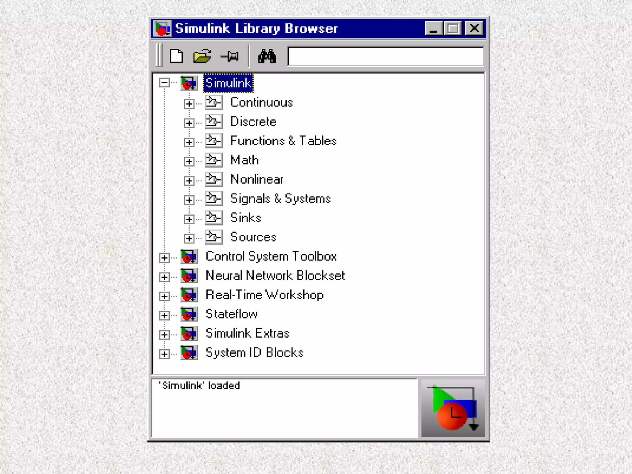
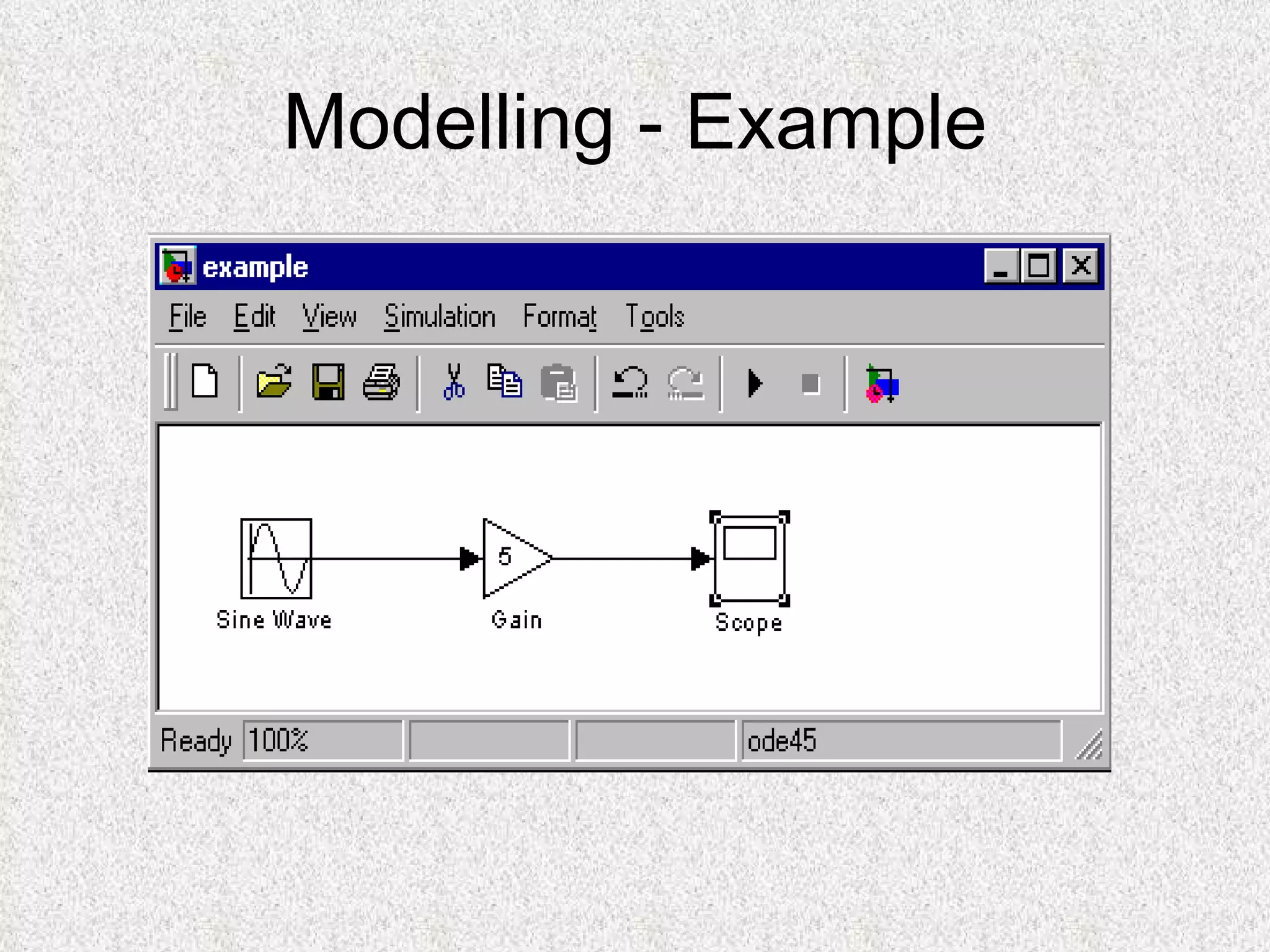
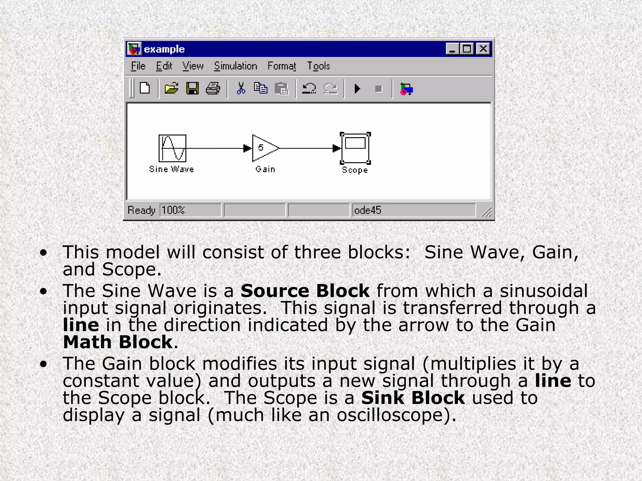
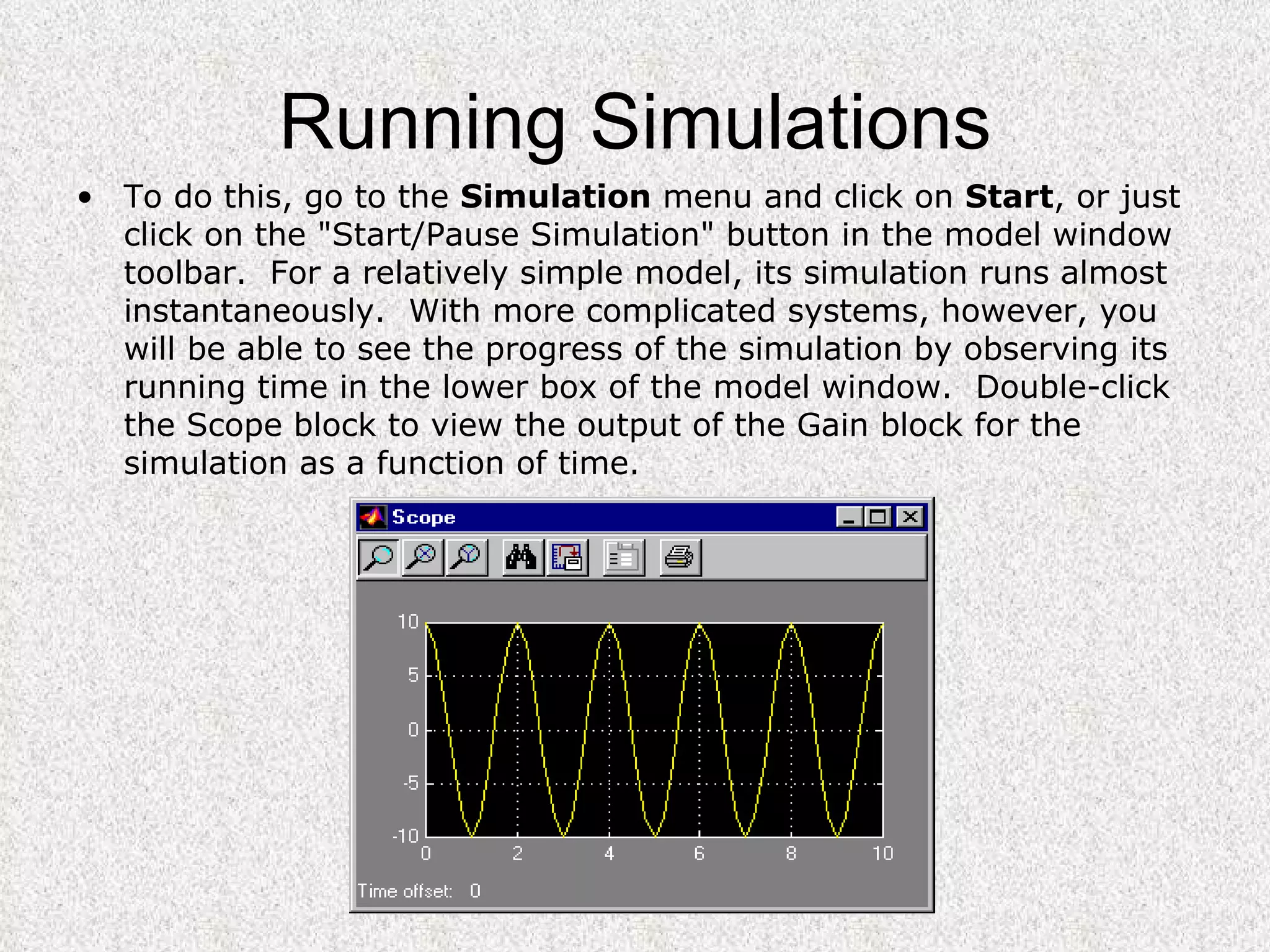
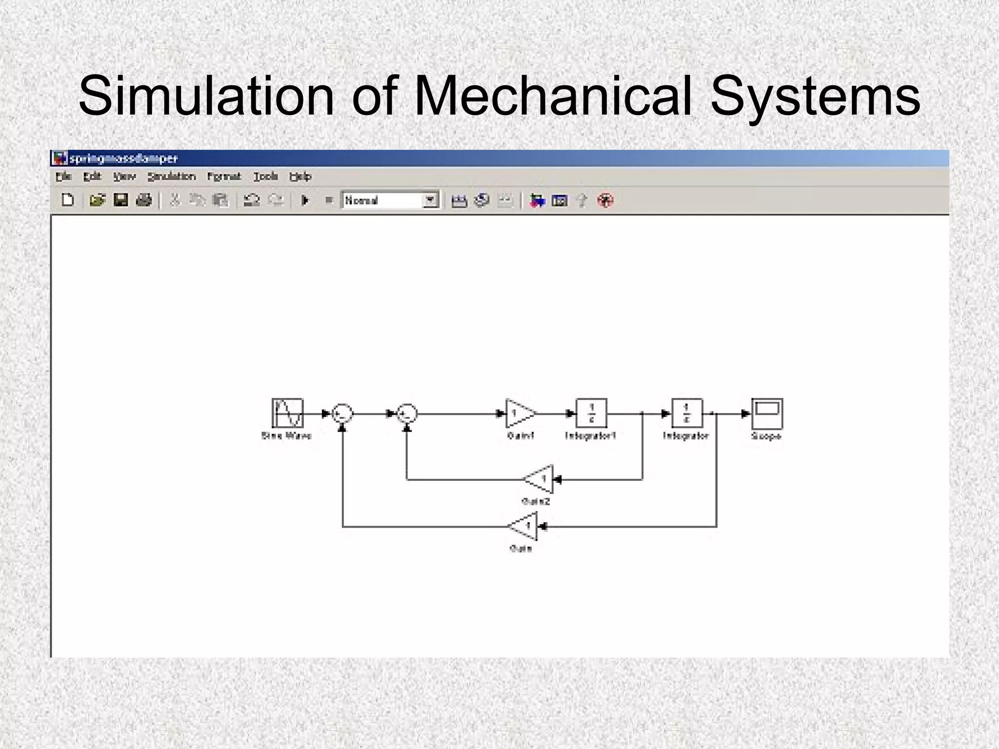

Simulink is a graphical extension of MATLAB used to model and simulate systems using block diagrams. It contains various block types like sources, sinks, math operations, and more that can be connected with lines to represent the system. The tutorial introduces starting Simulink, basic block and line elements, and demonstrates modeling a simple system with a sine wave source, gain block, and scope sink to view the output over time.