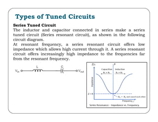
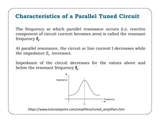
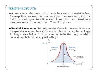
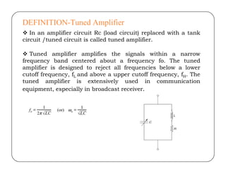
Tuned Amplifiers
Tuned Amplifiers
C Venkata Sudhakar
Assistant Professor, Department of ECE
Sree Vidyanikethan Engineering college
mail ID:sudhakar.chowdam@gmail.com
Contents:
Introduction to Tuned Amplifier
Q-Factor
Small signal tuned amplifier
Capacitance single tuned amplifier
Double Tuned Amplifier
Effect of Cascading single Tuned Amplifier
Staggered tuned Amplifiers
Stability of Tuned Amplifiers
Tuned Amplifier
Tuned amplifiers are used to for the amplification of a specific
frequency signal or a narrowband frequency signal. Basically
high frequency or radio frequency signals are amplified using
tuned amplifiers. Tuning (i.e., selecting) of frequency is done by
using a tuned or resonant circuit at the load.
Types of Tuned Circuits
Series Tuned Circuit
The inductor and capacitor connected in series make a series
tuned circuit (Series resonant circuit), as shown in the following
circuit diagram.
At resonant frequency, a series resonant circuit offers low
impedance which allows high current through it. A series resonant
circuit offers increasingly high impedance to the frequencies far
from the resonant frequency.
Parallel Tuned Circuit
The inductor and capacitor connected in parallel make a parallel
tuned circuit (parallel resonant circuit) , as shown in the below
figure.
At resonant frequency, a parallel
resonant circuit offers high impedance
which does not allow high current
through it. A parallel resonant circuit
offers increasingly low impedance to
the frequencies far from the resonant
frequency.
Characteristics of a Parallel Tuned Circuit
The frequency at which parallel resonance occurs (i.e. reactive
component of circuit current becomes zero) is called the resonant
frequency fr.
At parallel resonance, the circuit or line current I decreases while
the impedance Zr increases.
Impedance of the circuit decreases for the values above and
below the resonant frequency fr.
https://www.tutorialspoint.com/amplifiers/tuned_amplifiers.htm
RESONANCECIRCUITS:
At resonance, the tuned circuit can be used as a resistive load
for amplifiers because the reactance part becomes zero, i.e., the
inductive and capacitive effects cancel out. Hence the circuit acts
as a pure resistive one with both V and I in phase.
Parallel Resonance: For frequencies above fr, the circuit acts as
a capacitive one and hence the current leads the applied voltage.
At frequencies below fr, it acts as an inductive one, in which
current lags behind the applied voltage.
Advantages of Tuned Amplifiers
The usage of reactive components like L and C, minimizes the
power loss, which makes the tuned amplifiers efficient.
 The selectivity and amplification of desired frequency is high, by
providing higher impedance at resonant frequency.
 A smaller collector supply VCC would do, because of its little
resistance in parallel tuned circuit.
Disadvantages of Tuned amplifiers
The overall circuitry is costly as well as bulky due to the
presence of inductors and capacitors in tuned circuits.
Amplification in the range of audio frequency cannot be
achieved.
Increase in bandwidth leads to complexity in the circuit.
Q-factor
The Q-factor as quality factor of an inductor at operating
frequency ‘ω’ is defined as the ratio of impedance of the coil to its
resistance and can be defined as
The lower coil Resistance, gives the better Q-factor for an
inductor coil. The higher the value of Q, the sharper resonance
curve and better selectivity will be
Q-factor of Inductor is ωL/R
Q-factor of Capacitor is 1/ωCR
Frequency Response of Tuned
Amplifier
For an amplifier to be efficient, its gain should be high. This
voltage gain depends upon β, input impedance and collector
load. The collector load in a tuned amplifier is a tuned circuit.
The voltage gain of such an amplifier is given by
Where ZC = effective collector load and Zin = input impedance
of the amplifier.
The value of ZC depends upon the frequency of the tuned
amplifier. As ZC is maximum at resonant frequency, the gain
of the amplifier is maximum at this resonant frequency.
Bandwidth
The range of frequencies at which the voltage gain of the tuned
amplifier falls to 70.7% of the maximum gain is called its
Bandwidth.
 The bandwidth of a tuned amplifier depends upon the Q of the
LC circuit i.e., upon the sharpness of the frequency response. The
value of Q and the bandwidth are inversely proportional.
Figure shows the bandwidth and frequency response of the
tuned amplifier.
BW = f2-f1
Relation between Q and Bandwidth
The quality factor Q of the bandwidth is defined as the ratio of
resonant frequency to bandwidth, i.e.,
In general, a practical circuit has its Q value greater than 10.
Under this condition, the resonant frequency at parallel
resonance is given by
Q-factor of Inductor
The Q-factor of a inductor at the operating frequency ‘ω ’ is the
ratio of reactance of the inductor to its series resistor (R).
Q-factor of Inductor
Q-factor of Capacitor
The Q-factor of a capacitor at the operating frequency
‘ω ’ is the ratio of reactance of the capacitor to its series resistor (R).
Q of lossy capacitor
17
18
Q
DEFINITION-Tuned Amplifier
 In an amplifier circuit Rc (load circuit) replaced with a tank
circuit /tuned circuit is called tuned amplifier.
 Tuned amplifier amplifies the signals within a narrow
frequency band centered about a frequency fo. The tuned
amplifier is designed to reject all frequencies below a lower
cutoff frequency, fL and above a upper cutoff frequency, fH. The
tuned amplifier is extensively used in communication
equipment, especially in broadcast receiver.
Cont’d….
The gain of a transistor amplifier is directly proportional to the
value of its load impedance. A parallel tuned circuit has high
impedance at its frequency of resonance and the impedance falls
off sharply as the frequency departs from the frequency of
resonance. Hence, the gain versus frequency curve of the
tuned amplifier is almost similar to the impedance versus
frequency curve of the tuned amplifier.
Classification of
Tuned Circuits
Small signal amplifier,
low power, radio
frequency
Large signal amplifier,
large power, radio
frequency
ClassA
Single Tuned
circuit(one
parallel circuit
is employed)
Double tuned
circuit(two
tuned circuit
are employed)
Staggered
Tuned amplifier
Class AB, B & C
Shunt peaked
tuned with
higher band
width
CLASSIFICATION OF TUNEDAMPLIFIERS
Small Signal Tuned Amplifiers :- They are used to amplify
the RF signals of small magnitude.
They are further classified as:
(a)SingleTuned Amplifiers:-Single tuned amplifiers use
one parallel resonant circuit as the load impedance in
each stage and all the tuned circuits are tuned to the
same frequency.
(b)Double Tuned Amplifiers:- In this we use two
mutually coupled tuned circuits for every stage both of
tuned circuits are tuned at same freq.
(c)Stagger Tuned Amplifiers:- Stagger tuned amplifiers use
a number of single tuned stages in cascade, the successive
tuned circuits being tuned to slightly different frequencies.
Single tuned amplifiers can be further classified as
(a) capacitance coupled single tuned amplifier and
(b) transformer coupled or inductively coupled single tuned
amplifier.
Capacitive coupled single tuned Amplifier
An amplifier circuit with a single tuner section
being at the collector of the amplifier circuit is
called as Single tuner amplifier circuit.
A simple transistor amplifier circuit
consisting of a parallel tuned circuit
in its collector load, makes a single
tuned amplifier circuit. The values of
capacitance and inductance of the
tuned circuit are selected such that its
resonant frequency is equal to the
frequency to be amplified.
The tuned circuit offers high impedance at tuned frequency, which helps to
offer high output across the tuned circuit , all the other frequencies which get
lower impedance
AC Analysis
Figure gives the equivalent circuit for the tuned amplifier using
high frequency hybrid-π model for the transistor.
24
Here, A is the voltage gain of the amplifier. C1 and C2 are the stray wiring
capacitances in the input and output circuits, respectively.
The equivalent circuit shown in Figure can be simplified where all the
capacitances in the input circuit can be grouped together to form CS given by
Similarly, all the capacitances in the output circuit can be grouped together
to form C given by
Similarly
Similarly
where R o is the output resistance of current generator gm Vb’e.
The reactances of the bypass capacitor CE and the coupling capacitor CC are
negligibly small at the operating frequency and these elements can be
neglected in the simplified equivalent circuit shown in Figure
9
2
The output circuit of the amplifier can be modified as shown in Figure
Taking Rt as the parallel combination of Ro, RP and Ri, i.e.
28
Impedance Z
Z is the impedance of C, L and Rt
in parallel. The admittance Y is
given by
Impedance Z cont’d…
Let δ indicate the fractional frequency variation, i.e., variation in
frequency expressed as a fraction of the resonant frequency.
Then
or
Impedance Z at resonance cont’d…
The output circuit can be modified as shown in Figure
From the output circuit shown in Fig.
From the simplified circuit neglecting Cs
Substituting in the above equation we get voltage gain
Bandwidth
SINGLETUNEDAMPLIFIER USINGFET
LIMITATION:
• This tuned amplifier are required to be highly selective.
But high selectivity required a tuned circuit with a high Q-
factor .
• A high Q- factor circuit will give a high Av but at the
same time , it will give much reduced band with because
bandwidth is inversely proportional to the Q- factor .
• It means that tuned amplifier with reduce bandwidth may
not be able to amplify equally the complete band of
signals & result is poor reproduction . This is called
potential instability in tuned amplifier.
Double tuned Amplifier:
38
39
40
41
42
43
44
45
STAGGERTUNEDAMPLIFIERS:
47
48
Stability Considerations
49
Video Amplifiers (IC MC1550)
APPLICATIONS OF TUNED AMPLIFIER
Tuned amplifiers serve the best for two purposes:
a) Selection of desired frequency.
b) Amplifying the signal to a desired level.
USED IN:
USED IN:
Communication transmitters and receivers.
In filter design :--Band Pass, low pass, High pass and
band reject filter design.
ADVANTAGES
It provides high selectivity.
It has small collector voltage.
Power loss is also less.
Signal to noise ratio of O/P is good.
They are well suited for radio transmitters and
receivers .
DISADVANTAGES
They are not suitable to amplify audio
frequencies.
If the band of frequency is increase then design
becomes complex.
Since they use inductors and capacitors as tuning
elements, the circuit is bulky and costly.
 References
•
•
•
“Integrated Electronics”, J. Milliman and C.C.
Halkias, Tata McGraw Hill, 1972
“Electronic Circuit Analysis- B.V. Rao, K.R.Rjeswari,
P.C.R.Pantulu- Pearson publication
“Electronic Devices and Circuits” – Salivahanan, Suresh
•
•
•
•
“Electronic Devices and Circuits” – Salivahanan, Suresh
Kumar,
A.Vallavaraj, TATA McGraw
Hill www.nptel.ac.in
www.nesoacademy.org
www.tutorialspoint.com
Thank you
Thank you

BJT Tuned amplifiers

  • 1.
    Tuned Amplifiers Tuned Amplifiers CVenkata Sudhakar Assistant Professor, Department of ECE Sree Vidyanikethan Engineering college mail ID:sudhakar.chowdam@gmail.com
  • 2.
    Contents: Introduction to TunedAmplifier Q-Factor Small signal tuned amplifier Capacitance single tuned amplifier Double Tuned Amplifier Double Tuned Amplifier Effect of Cascading single Tuned Amplifier Staggered tuned Amplifiers Stability of Tuned Amplifiers
  • 3.
    Tuned Amplifier Tuned amplifiersare used to for the amplification of a specific frequency signal or a narrowband frequency signal. Basically high frequency or radio frequency signals are amplified using tuned amplifiers. Tuning (i.e., selecting) of frequency is done by using a tuned or resonant circuit at the load. using a tuned or resonant circuit at the load.
  • 4.
    Types of TunedCircuits Series Tuned Circuit The inductor and capacitor connected in series make a series tuned circuit (Series resonant circuit), as shown in the following circuit diagram. At resonant frequency, a series resonant circuit offers low impedance which allows high current through it. A series resonant circuit offers increasingly high impedance to the frequencies far from the resonant frequency.
  • 5.
    Parallel Tuned Circuit Theinductor and capacitor connected in parallel make a parallel tuned circuit (parallel resonant circuit) , as shown in the below figure. At resonant frequency, a parallel resonant circuit offers high impedance which does not allow high current through it. A parallel resonant circuit offers increasingly low impedance to offers increasingly low impedance to the frequencies far from the resonant frequency.
  • 6.
    Characteristics of aParallel Tuned Circuit The frequency at which parallel resonance occurs (i.e. reactive component of circuit current becomes zero) is called the resonant frequency fr. At parallel resonance, the circuit or line current I decreases while the impedance Zr increases. Impedance of the circuit decreases for the values above and Impedance of the circuit decreases for the values above and below the resonant frequency fr. https://www.tutorialspoint.com/amplifiers/tuned_amplifiers.htm
  • 7.
    RESONANCECIRCUITS: At resonance, thetuned circuit can be used as a resistive load for amplifiers because the reactance part becomes zero, i.e., the inductive and capacitive effects cancel out. Hence the circuit acts as a pure resistive one with both V and I in phase. Parallel Resonance: For frequencies above fr, the circuit acts as a capacitive one and hence the current leads the applied voltage. At frequencies below fr, it acts as an inductive one, in which current lags behind the applied voltage. current lags behind the applied voltage.
  • 8.
    Advantages of TunedAmplifiers The usage of reactive components like L and C, minimizes the power loss, which makes the tuned amplifiers efficient.  The selectivity and amplification of desired frequency is high, by providing higher impedance at resonant frequency.  A smaller collector supply VCC would do, because of its little resistance in parallel tuned circuit. resistance in parallel tuned circuit. Disadvantages of Tuned amplifiers The overall circuitry is costly as well as bulky due to the presence of inductors and capacitors in tuned circuits. Amplification in the range of audio frequency cannot be achieved. Increase in bandwidth leads to complexity in the circuit.
  • 9.
    Q-factor The Q-factor asquality factor of an inductor at operating frequency ‘ω’ is defined as the ratio of impedance of the coil to its resistance and can be defined as The lower coil Resistance, gives the better Q-factor for an inductor coil. The higher the value of Q, the sharper resonance curve and better selectivity will be Q-factor of Inductor is ωL/R Q-factor of Capacitor is 1/ωCR
  • 10.
    Frequency Response ofTuned Amplifier For an amplifier to be efficient, its gain should be high. This voltage gain depends upon β, input impedance and collector load. The collector load in a tuned amplifier is a tuned circuit. The voltage gain of such an amplifier is given by Where ZC = effective collector load and Zin = input impedance of the amplifier. The value of ZC depends upon the frequency of the tuned amplifier. As ZC is maximum at resonant frequency, the gain of the amplifier is maximum at this resonant frequency.
  • 11.
    Bandwidth The range offrequencies at which the voltage gain of the tuned amplifier falls to 70.7% of the maximum gain is called its Bandwidth.  The bandwidth of a tuned amplifier depends upon the Q of the LC circuit i.e., upon the sharpness of the frequency response. The value of Q and the bandwidth are inversely proportional. Figure shows the bandwidth and frequency response of the Figure shows the bandwidth and frequency response of the tuned amplifier. BW = f2-f1
  • 12.
    Relation between Qand Bandwidth The quality factor Q of the bandwidth is defined as the ratio of resonant frequency to bandwidth, i.e., In general, a practical circuit has its Q value greater than 10. Under this condition, the resonant frequency at parallel resonance is given by
  • 13.
    Q-factor of Inductor TheQ-factor of a inductor at the operating frequency ‘ω ’ is the ratio of reactance of the inductor to its series resistor (R).
  • 14.
  • 15.
    Q-factor of Capacitor TheQ-factor of a capacitor at the operating frequency ‘ω ’ is the ratio of reactance of the capacitor to its series resistor (R).
  • 16.
    Q of lossycapacitor
  • 17.
  • 18.
  • 19.
    DEFINITION-Tuned Amplifier  Inan amplifier circuit Rc (load circuit) replaced with a tank circuit /tuned circuit is called tuned amplifier.  Tuned amplifier amplifies the signals within a narrow frequency band centered about a frequency fo. The tuned amplifier is designed to reject all frequencies below a lower cutoff frequency, fL and above a upper cutoff frequency, fH. The tuned amplifier is extensively used in communication equipment, especially in broadcast receiver. equipment, especially in broadcast receiver.
  • 20.
    Cont’d…. The gain ofa transistor amplifier is directly proportional to the value of its load impedance. A parallel tuned circuit has high impedance at its frequency of resonance and the impedance falls off sharply as the frequency departs from the frequency of resonance. Hence, the gain versus frequency curve of the tuned amplifier is almost similar to the impedance versus frequency curve of the tuned amplifier.
  • 21.
    Classification of Tuned Circuits Smallsignal amplifier, low power, radio frequency Large signal amplifier, large power, radio frequency ClassA Single Tuned circuit(one parallel circuit is employed) Double tuned circuit(two tuned circuit are employed) Staggered Tuned amplifier Class AB, B & C Shunt peaked tuned with higher band width
  • 22.
    CLASSIFICATION OF TUNEDAMPLIFIERS SmallSignal Tuned Amplifiers :- They are used to amplify the RF signals of small magnitude. They are further classified as: (a)SingleTuned Amplifiers:-Single tuned amplifiers use one parallel resonant circuit as the load impedance in each stage and all the tuned circuits are tuned to the same frequency. (b)Double Tuned Amplifiers:- In this we use two (b)Double Tuned Amplifiers:- In this we use two mutually coupled tuned circuits for every stage both of tuned circuits are tuned at same freq. (c)Stagger Tuned Amplifiers:- Stagger tuned amplifiers use a number of single tuned stages in cascade, the successive tuned circuits being tuned to slightly different frequencies. Single tuned amplifiers can be further classified as (a) capacitance coupled single tuned amplifier and (b) transformer coupled or inductively coupled single tuned amplifier.
  • 23.
    Capacitive coupled singletuned Amplifier An amplifier circuit with a single tuner section being at the collector of the amplifier circuit is called as Single tuner amplifier circuit. A simple transistor amplifier circuit consisting of a parallel tuned circuit in its collector load, makes a single tuned amplifier circuit. The values of tuned amplifier circuit. The values of capacitance and inductance of the tuned circuit are selected such that its resonant frequency is equal to the frequency to be amplified. The tuned circuit offers high impedance at tuned frequency, which helps to offer high output across the tuned circuit , all the other frequencies which get lower impedance
  • 24.
    AC Analysis Figure givesthe equivalent circuit for the tuned amplifier using high frequency hybrid-π model for the transistor. 24
  • 25.
    Here, A isthe voltage gain of the amplifier. C1 and C2 are the stray wiring capacitances in the input and output circuits, respectively. The equivalent circuit shown in Figure can be simplified where all the capacitances in the input circuit can be grouped together to form CS given by Similarly, all the capacitances in the output circuit can be grouped together to form C given by Similarly Similarly where R o is the output resistance of current generator gm Vb’e.
  • 26.
    The reactances ofthe bypass capacitor CE and the coupling capacitor CC are negligibly small at the operating frequency and these elements can be neglected in the simplified equivalent circuit shown in Figure
  • 27.
  • 28.
    The output circuitof the amplifier can be modified as shown in Figure Taking Rt as the parallel combination of Ro, RP and Ri, i.e. 28
  • 29.
    Impedance Z Z isthe impedance of C, L and Rt in parallel. The admittance Y is given by
  • 30.
    Impedance Z cont’d… Letδ indicate the fractional frequency variation, i.e., variation in frequency expressed as a fraction of the resonant frequency. Then or
  • 31.
    Impedance Z atresonance cont’d…
  • 32.
    The output circuitcan be modified as shown in Figure From the output circuit shown in Fig. From the simplified circuit neglecting Cs Substituting in the above equation we get voltage gain
  • 34.
  • 35.
  • 36.
    LIMITATION: • This tunedamplifier are required to be highly selective. But high selectivity required a tuned circuit with a high Q- factor . • A high Q- factor circuit will give a high Av but at the same time , it will give much reduced band with because bandwidth is inversely proportional to the Q- factor . bandwidth is inversely proportional to the Q- factor . • It means that tuned amplifier with reduce bandwidth may not be able to amplify equally the complete band of signals & result is poor reproduction . This is called potential instability in tuned amplifier.
  • 37.
  • 38.
  • 39.
  • 40.
  • 41.
  • 42.
  • 43.
  • 44.
  • 45.
  • 46.
  • 47.
  • 48.
  • 49.
  • 58.
  • 60.
    APPLICATIONS OF TUNEDAMPLIFIER Tuned amplifiers serve the best for two purposes: a) Selection of desired frequency. b) Amplifying the signal to a desired level. USED IN: USED IN: Communication transmitters and receivers. In filter design :--Band Pass, low pass, High pass and band reject filter design.
  • 61.
    ADVANTAGES It provides highselectivity. It has small collector voltage. Power loss is also less. Signal to noise ratio of O/P is good. Signal to noise ratio of O/P is good. They are well suited for radio transmitters and receivers .
  • 62.
    DISADVANTAGES They are notsuitable to amplify audio frequencies. If the band of frequency is increase then design becomes complex. Since they use inductors and capacitors as tuning elements, the circuit is bulky and costly.
  • 63.
     References • • • “Integrated Electronics”,J. Milliman and C.C. Halkias, Tata McGraw Hill, 1972 “Electronic Circuit Analysis- B.V. Rao, K.R.Rjeswari, P.C.R.Pantulu- Pearson publication “Electronic Devices and Circuits” – Salivahanan, Suresh • • • • “Electronic Devices and Circuits” – Salivahanan, Suresh Kumar, A.Vallavaraj, TATA McGraw Hill www.nptel.ac.in www.nesoacademy.org www.tutorialspoint.com
  • 64.