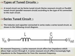
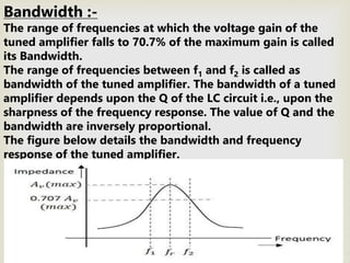
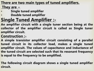
F-18TC Roll no.22

The types of amplifiers that we have discussed so far cannot work effectively at
radio frequencies, even though they are good at audio frequencies. Also, the gain
of these amplifiers is such that it will not vary according to the frequency of the
signal, over a wide range. This allows the amplification of the signal equally well
over a range of frequencies and does not permit the selection of particular desired
frequency while rejecting the other frequencies.
So, there occurs a need for a circuit which can select as well as amplify. So, an
amplifier circuit along with a selection, such as a tuned circuit makes a Tuned
amplifier.
What is a Tuned Amplifier?
 Tuned amplifiers are the amplifiers that are employed for the purpose
of tuning. Tuning means selecting. Among a set of frequencies available, if
there occurs a need to select a particular frequency, while rejecting all other
frequencies, such a process is called Selection. This selection is done by using a
circuit called as Tuned circuit.
INTRODUCTION TO
TUNED AMPLIFIER
The basic tuned amplifier circuit looks as shown.
below.
When an amplifier circuit has its load replaced by a tuned
circuit, such an amplifier can be called as a Tuned amplifier
circuit.
The tuner circuit is nothing but a LC circuit which is
also called as resonant or tank circuit. It selects the
frequency. A tuned circuit is capable of amplifying
a signal over a narrow band of frequencies that are
centered at resonant frequency.
When the reactance of the inductor balances the
reactance of the capacitor, in the tuned circuit at
some frequency, such a frequency can be called
as resonant frequency. It is denoted by fr.
The formula for resonance is :-
 2πfL=1/2πfc
 fr=1/2π√LC
Types of Tuned Circuits :-
 A tuned circuit can be Series tuned circuit (Series resonant circuit) or Parallel
tuned circuit (parallel resonant circuit) according to the type of its connection
to the main circuit.
Series Tuned Circuit :-
 The inductor and capacitor connected in series make a series tuned circuit, as
shown in the following circuit diagram.
At resonant frequency, a series resonant circuit offers low impedance which
allows high current through it. A series resonant circuit offers increasingly high
impedance to the frequencies far from the resonant frequency.
Parallel Tuned Circuit :-
The inductor and capacitor connected in parallel make a parallel tuned circuit, as
shown in the below figure.
At resonant frequency, a parallel resonant circuit offers high impedance which
does not allow high current through it. A parallel resonant circuit offers
increasingly low impedance to the frequencies far from the resonant frequency.
Characteristics of a Parallel Tuned Circuit :-
 The frequency at which parallel resonance occurs (i.e. reactive
component of circuit current becomes zero) is called the resonant
frequency fr . The main characteristics of a tuned circuit are as
follows.
Impedance :-
 The ratio of supply voltage to the line current is the impedance of the
tuned circuit. Impedance offered by LC circuit is given by
 Supplyvoltage/Lineequation=V/I
 At resonance, the line current increases while the impedance
decreases. Figure below :
Impedance of the circuit decreases for the
values above and below the resonant
frequency fr. Hence the selection of a
particular frequency and rejection of other
frequencies is possible.
Therefore, circuit impedance Zr is obtained as
ZR=L/CR
Thus at parallel resonance, the circuit
impedance is equal to L/CR.
Circuit Current :-
At parallel resonance, the circuit or line
current I is given by the applied voltage
divided by the circuit impedance Zr
i.e. Line Current I=V/Zr
Where Zr=L/CR
Because Zr is very high, the line current I will
be very small.
Quality Factor :-
For a parallel resonance circuit, the sharpness of
the resonance curve determines the selectivity.
The smaller the resistance of the coil, the sharper
the resonant curve will be. Hence the inductive
reactance and resistance of the coil determine the
quality of the tuned circuit.
The ratio of inductive reactance of the coil at
resonance to its resistance is known as Quality
factor. It is denoted by Q.
Q=XL/R=2πfrL/R
The higher the value of Q, the sharper the
resonance curve and the better the selectivity will
be.
Advantages of Tuned Amplifiers :-
 The usage of reactive components like L and C, minimizes the power
loss, which makes the tuned amplifiers efficient.
 The selectivity and amplification of desired frequency is high, by
providing higher impedance at resonant frequency.
 A smaller collector supply VCC would do, because of its little resistance
in parallel tuned circuit.
 It is important to remember that these advantages are not applicable
when there is a high resistive collector load.
Frequency Response of Tuned Amplifier :-
 For an amplifier to be efficient, its gain should be high. This voltage
gain depends upon β, input impedance and collector load. The collector
load in a tuned amplifier is a tuned circuit.
 The voltage gain of such an amplifier is given by:
 Voltage gain = βZC/Zin
 Where ZC = effective collector load and Zin = input impedance of the
amplifier.
 The value of ZC depends upon the frequency of the tuned amplifier. As
ZC is maximum at resonant frequency, the gain of the amplifier is
maximum at this resonant frequency.
Bandwidth :-
The range of frequencies at which the voltage gain of the
tuned amplifier falls to 70.7% of the maximum gain is called
its Bandwidth.
The range of frequencies between f1 and f2 is called as
bandwidth of the tuned amplifier. The bandwidth of a tuned
amplifier depends upon the Q of the LC circuit i.e., upon the
sharpness of the frequency response. The value of Q and the
bandwidth are inversely proportional.
The figure below details the bandwidth and frequency
response of the tuned amplifier.
Relation between Q and Bandwidth :-
The quality factor Q of the bandwidth is defined as the
ratio of resonant frequency to bandwidth:
i.e. Q=fr/BW
In general, a practical circuit has its Q value greater than
10.
Under this condition, the resonant frequency at parallel
resonance is given by:
fr=1/2π√ LC
There are two main types of tuned amplifiers.
They are −
• Single tuned amplifier
• Double tuned amplifier
Single Tuned Amplifier :-
An amplifier circuit with a single tuner section being at the
collector of the amplifier circuit is called as Single tuner
amplifier circuit.
Construction :-
A simple transistor amplifier circuit consisting of a parallel
tuned circuit in its collector load, makes a single tuned
amplifier circuit. The values of capacitance and inductance of
the tuned circuit are selected such that its resonant frequency
is equal to the frequency to be amplified.
The following circuit diagram shows a single tuned amplifier
circuit.
The output can be obtained from the coupling capacitor CC as shown above or
from a secondary winding placed at L.
Operation :-
The high frequency signal that has to be amplified is applied at the input
of the amplifier. The resonant frequency of the parallel tuned circuit is
made equal to the frequency of the signal applied by altering the
capacitance value of the capacitor C, in the tuned circuit.
At this stage, the tuned circuit offers high impedance to the signal
frequency, which helps to offer high output across the tuned circuit. As
high impedance is offered only for the tuned frequency, all the other
frequencies which get lower impedance are rejected by the tuned circuit.
Hence the tuned amplifier selects and amplifies the desired frequency
signal.
Frequency Response:-
The parallel resonance occurs at resonant frequency fr when the circuit has
a high Q. the resonant frequency fr is given by : -
The following graph show below : - fr=1/2π√LC
At resonant frequency fr the impedance of parallel tuned circuit is very
high and is purely resistive. The voltage across RL is therefore maximum,
when the circuit is tuned to resonant frequency. Hence the voltage gain is
maximum at resonant frequency and drops off above and below it. The
higher the Q, the narrower will the curve be.
Double Tuned Amplifier :-
An amplifier circuit with a double tuner section being at the
collector of the amplifier circuit is called as Double tuner
amplifier circuit.
Construction :-
The construction of double tuned amplifier is understood by
having a look at the following figure. This circuit consists of
two tuned circuits L1C1 and L2C2 in the collector section of the
amplifier. The signal at the output of the tuned circuit L1C1 is
coupled to the other tuned circuit L2C2 through mutual
coupling method. The remaining circuit details are same as in
the single tuned amplifier circuit.
As shown in the following circuit diagram.
Operation :-
The high frequency signal which has to be amplified is given
to the input of the amplifier. The tuning circuit L1C1 is tuned
to the input signal frequency. At this condition, the tuned
circuit offers high reactance to the signal frequency.
Consequently, large output appears at the output of the
tuned circuit L1C1 which is then coupled to the other tuned
circuit L2C2 through mutual induction. These double tuned
circuits are extensively used for coupling various circuits of
radio and television receivers.
Frequency Response of Double
Tuned Amplifier :-
The double tuned amplifier has the special feature
of coupling which is important in determining the frequency
response of the amplifier. The amount of mutual inductance
between the two tuned circuits states the degree of coupling,
which determines the frequency response of the circuit.
In order to have an idea on the mutual inductance property, let us go through
the basic principle.
Mutual Inductance :-
As the current carrying coil produces some magnetic field around it, if
another coil is brought near this coil, such that it is in the magnetic flux
region of the primary, then the varying magnetic flux induces an EMF in
the second coil. If this first coil is called as Primary coil, the second one
can be called as a Secondary coil.
When the EMF is induced in the secondary coil due to the varying
magnetic field of the primary coil, then such phenomenon is called as
the Mutual Inductance.
The figure below gives an idea about this.
The current is in the figure indicate the source current
while iind indicates the induced current. The flux represents the
magnetic flux created around the coil. This spreads to the
secondary coil also.
With the application of voltage, the current is flows and flux
gets created. When the current is varies the flux gets varied,
producing iind in the secondary coil, due to the Mutual
inductance property.
Coupling :-
Under the concept of mutual inductance coupling will be as shown in
the figure below.
When the coils are spaced apart, the flux linkages of primary coil L1 will not
link the secondary coil L2. At this condition, the coils are said to have Loose
coupling. The resistance reflected from the secondary coil at this condition
is small and the resonance curve will be sharp and the circuit Q is high as
shown in the figure below.
On the contrary, when the primary and secondary coils are
brought close together, they have Tight coupling. Under such
conditions, the reflected resistance will be large and the
circuit Q is lower. Two positions of gain maxima, one above
and the other below the resonant frequency are obtained.
The above figure clearly states that the bandwidth
increases with the degree of coupling. The
determining factor in a double tuned circuit is not Q
but the coupling.
We understood that, for a given frequency, the
tighter the coupling the greater the bandwidth will
be.
The equation for bandwidth is given as :
BWdt = kfr
Where BWdt = bandwidth for double tuned circuit,
K = coefficient of coupling, and fr = resonant frequency.
Bandwidth of Double Tuned Circuit :

THANK YOU SIR FOR
GIVE ME A CHANCE
TO COME ON THE
STAGE AT THAT
MOMENT

Presentation 2

  • 1.
  • 3.
     The types ofamplifiers that we have discussed so far cannot work effectively at radio frequencies, even though they are good at audio frequencies. Also, the gain of these amplifiers is such that it will not vary according to the frequency of the signal, over a wide range. This allows the amplification of the signal equally well over a range of frequencies and does not permit the selection of particular desired frequency while rejecting the other frequencies. So, there occurs a need for a circuit which can select as well as amplify. So, an amplifier circuit along with a selection, such as a tuned circuit makes a Tuned amplifier. What is a Tuned Amplifier?  Tuned amplifiers are the amplifiers that are employed for the purpose of tuning. Tuning means selecting. Among a set of frequencies available, if there occurs a need to select a particular frequency, while rejecting all other frequencies, such a process is called Selection. This selection is done by using a circuit called as Tuned circuit. INTRODUCTION TO TUNED AMPLIFIER
  • 4.
    The basic tunedamplifier circuit looks as shown. below. When an amplifier circuit has its load replaced by a tuned circuit, such an amplifier can be called as a Tuned amplifier circuit.
  • 5.
    The tuner circuitis nothing but a LC circuit which is also called as resonant or tank circuit. It selects the frequency. A tuned circuit is capable of amplifying a signal over a narrow band of frequencies that are centered at resonant frequency. When the reactance of the inductor balances the reactance of the capacitor, in the tuned circuit at some frequency, such a frequency can be called as resonant frequency. It is denoted by fr. The formula for resonance is :-  2πfL=1/2πfc  fr=1/2π√LC
  • 6.
    Types of TunedCircuits :-  A tuned circuit can be Series tuned circuit (Series resonant circuit) or Parallel tuned circuit (parallel resonant circuit) according to the type of its connection to the main circuit. Series Tuned Circuit :-  The inductor and capacitor connected in series make a series tuned circuit, as shown in the following circuit diagram. At resonant frequency, a series resonant circuit offers low impedance which allows high current through it. A series resonant circuit offers increasingly high impedance to the frequencies far from the resonant frequency.
  • 7.
    Parallel Tuned Circuit:- The inductor and capacitor connected in parallel make a parallel tuned circuit, as shown in the below figure. At resonant frequency, a parallel resonant circuit offers high impedance which does not allow high current through it. A parallel resonant circuit offers increasingly low impedance to the frequencies far from the resonant frequency.
  • 8.
    Characteristics of aParallel Tuned Circuit :-  The frequency at which parallel resonance occurs (i.e. reactive component of circuit current becomes zero) is called the resonant frequency fr . The main characteristics of a tuned circuit are as follows. Impedance :-  The ratio of supply voltage to the line current is the impedance of the tuned circuit. Impedance offered by LC circuit is given by  Supplyvoltage/Lineequation=V/I  At resonance, the line current increases while the impedance decreases. Figure below :
  • 9.
    Impedance of thecircuit decreases for the values above and below the resonant frequency fr. Hence the selection of a particular frequency and rejection of other frequencies is possible. Therefore, circuit impedance Zr is obtained as ZR=L/CR Thus at parallel resonance, the circuit impedance is equal to L/CR. Circuit Current :- At parallel resonance, the circuit or line current I is given by the applied voltage divided by the circuit impedance Zr i.e. Line Current I=V/Zr Where Zr=L/CR Because Zr is very high, the line current I will be very small.
  • 10.
    Quality Factor :- Fora parallel resonance circuit, the sharpness of the resonance curve determines the selectivity. The smaller the resistance of the coil, the sharper the resonant curve will be. Hence the inductive reactance and resistance of the coil determine the quality of the tuned circuit. The ratio of inductive reactance of the coil at resonance to its resistance is known as Quality factor. It is denoted by Q. Q=XL/R=2πfrL/R The higher the value of Q, the sharper the resonance curve and the better the selectivity will be.
  • 11.
    Advantages of TunedAmplifiers :-  The usage of reactive components like L and C, minimizes the power loss, which makes the tuned amplifiers efficient.  The selectivity and amplification of desired frequency is high, by providing higher impedance at resonant frequency.  A smaller collector supply VCC would do, because of its little resistance in parallel tuned circuit.  It is important to remember that these advantages are not applicable when there is a high resistive collector load. Frequency Response of Tuned Amplifier :-  For an amplifier to be efficient, its gain should be high. This voltage gain depends upon β, input impedance and collector load. The collector load in a tuned amplifier is a tuned circuit.  The voltage gain of such an amplifier is given by:  Voltage gain = βZC/Zin  Where ZC = effective collector load and Zin = input impedance of the amplifier.  The value of ZC depends upon the frequency of the tuned amplifier. As ZC is maximum at resonant frequency, the gain of the amplifier is maximum at this resonant frequency.
  • 12.
    Bandwidth :- The rangeof frequencies at which the voltage gain of the tuned amplifier falls to 70.7% of the maximum gain is called its Bandwidth. The range of frequencies between f1 and f2 is called as bandwidth of the tuned amplifier. The bandwidth of a tuned amplifier depends upon the Q of the LC circuit i.e., upon the sharpness of the frequency response. The value of Q and the bandwidth are inversely proportional. The figure below details the bandwidth and frequency response of the tuned amplifier.
  • 13.
    Relation between Qand Bandwidth :- The quality factor Q of the bandwidth is defined as the ratio of resonant frequency to bandwidth: i.e. Q=fr/BW In general, a practical circuit has its Q value greater than 10. Under this condition, the resonant frequency at parallel resonance is given by: fr=1/2π√ LC
  • 14.
    There are twomain types of tuned amplifiers. They are − • Single tuned amplifier • Double tuned amplifier Single Tuned Amplifier :- An amplifier circuit with a single tuner section being at the collector of the amplifier circuit is called as Single tuner amplifier circuit. Construction :- A simple transistor amplifier circuit consisting of a parallel tuned circuit in its collector load, makes a single tuned amplifier circuit. The values of capacitance and inductance of the tuned circuit are selected such that its resonant frequency is equal to the frequency to be amplified. The following circuit diagram shows a single tuned amplifier circuit.
  • 15.
    The output canbe obtained from the coupling capacitor CC as shown above or from a secondary winding placed at L.
  • 16.
    Operation :- The highfrequency signal that has to be amplified is applied at the input of the amplifier. The resonant frequency of the parallel tuned circuit is made equal to the frequency of the signal applied by altering the capacitance value of the capacitor C, in the tuned circuit. At this stage, the tuned circuit offers high impedance to the signal frequency, which helps to offer high output across the tuned circuit. As high impedance is offered only for the tuned frequency, all the other frequencies which get lower impedance are rejected by the tuned circuit. Hence the tuned amplifier selects and amplifies the desired frequency signal. Frequency Response:- The parallel resonance occurs at resonant frequency fr when the circuit has a high Q. the resonant frequency fr is given by : - The following graph show below : - fr=1/2π√LC
  • 17.
    At resonant frequencyfr the impedance of parallel tuned circuit is very high and is purely resistive. The voltage across RL is therefore maximum, when the circuit is tuned to resonant frequency. Hence the voltage gain is maximum at resonant frequency and drops off above and below it. The higher the Q, the narrower will the curve be. Double Tuned Amplifier :- An amplifier circuit with a double tuner section being at the collector of the amplifier circuit is called as Double tuner amplifier circuit. Construction :- The construction of double tuned amplifier is understood by having a look at the following figure. This circuit consists of two tuned circuits L1C1 and L2C2 in the collector section of the amplifier. The signal at the output of the tuned circuit L1C1 is coupled to the other tuned circuit L2C2 through mutual coupling method. The remaining circuit details are same as in the single tuned amplifier circuit.
  • 18.
    As shown inthe following circuit diagram.
  • 19.
    Operation :- The highfrequency signal which has to be amplified is given to the input of the amplifier. The tuning circuit L1C1 is tuned to the input signal frequency. At this condition, the tuned circuit offers high reactance to the signal frequency. Consequently, large output appears at the output of the tuned circuit L1C1 which is then coupled to the other tuned circuit L2C2 through mutual induction. These double tuned circuits are extensively used for coupling various circuits of radio and television receivers. Frequency Response of Double Tuned Amplifier :- The double tuned amplifier has the special feature of coupling which is important in determining the frequency response of the amplifier. The amount of mutual inductance between the two tuned circuits states the degree of coupling, which determines the frequency response of the circuit.
  • 20.
    In order tohave an idea on the mutual inductance property, let us go through the basic principle. Mutual Inductance :- As the current carrying coil produces some magnetic field around it, if another coil is brought near this coil, such that it is in the magnetic flux region of the primary, then the varying magnetic flux induces an EMF in the second coil. If this first coil is called as Primary coil, the second one can be called as a Secondary coil. When the EMF is induced in the secondary coil due to the varying magnetic field of the primary coil, then such phenomenon is called as the Mutual Inductance. The figure below gives an idea about this.
  • 21.
    The current isin the figure indicate the source current while iind indicates the induced current. The flux represents the magnetic flux created around the coil. This spreads to the secondary coil also. With the application of voltage, the current is flows and flux gets created. When the current is varies the flux gets varied, producing iind in the secondary coil, due to the Mutual inductance property. Coupling :- Under the concept of mutual inductance coupling will be as shown in the figure below.
  • 22.
    When the coilsare spaced apart, the flux linkages of primary coil L1 will not link the secondary coil L2. At this condition, the coils are said to have Loose coupling. The resistance reflected from the secondary coil at this condition is small and the resonance curve will be sharp and the circuit Q is high as shown in the figure below. On the contrary, when the primary and secondary coils are brought close together, they have Tight coupling. Under such conditions, the reflected resistance will be large and the circuit Q is lower. Two positions of gain maxima, one above and the other below the resonant frequency are obtained.
  • 23.
    The above figureclearly states that the bandwidth increases with the degree of coupling. The determining factor in a double tuned circuit is not Q but the coupling. We understood that, for a given frequency, the tighter the coupling the greater the bandwidth will be. The equation for bandwidth is given as : BWdt = kfr Where BWdt = bandwidth for double tuned circuit, K = coefficient of coupling, and fr = resonant frequency. Bandwidth of Double Tuned Circuit :
  • 24.
     THANK YOU SIRFOR GIVE ME A CHANCE TO COME ON THE STAGE AT THAT MOMENT