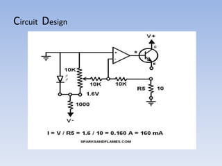
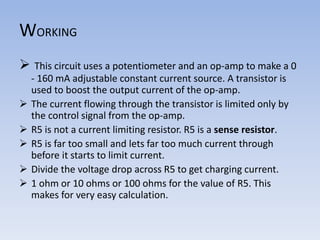
BATTERY CHARGING CIRCUIT
NAME : KARTHIK.J.M
ROLL NO : 42
USN : 2BV13EC035
GUIDED BY
SNEHA.V.METI
Presentation Outline
Introduction
Basic circuit diagram
Application
Working
Source
INTRODUCTION
 OP AMP is a dc coupled high gain electronic voltage amplifier with a
differential input and usually a single ended output.
 OP AMP was invented by KARL.D.SWARTZEL JR in 1941.
 OP AMP has revolutioned the analog electronic field with
its wide variety applications .
 First it was used in analog computers for arithmatic and logic
operations.
INTERNAL CIRCUIT DIAGRAM OF OP AMP
SYMBOLIC REPRESENTATION
 V+ : Non inverting input
 v- : Inverting input
 vout : Output terminal
 V+ : Non inverting input
 v+ : Positive power supply
 v- : Negative power supply
 Current Limiting is the practice in electronic circuits of
imposing an upper limit on the current that may be delivered
to a load with the purpose of protecting the circuit generating
or transmitting the current from harmful effects due to
a short-circuit or similar problem in the load.
 The simplest form of current limiting for mains is
fuse. A circuit breaker is another device for mains current
limiting.
LIMITING CIRCUITS
CONTINUED..
 Classic 2 NPN transistor current limiter
 NPN + op amp current limiter
 Mosfet current limiter
CHARGER WITH LIMITING CIRCUIT
 The charger circuit is fundamental unit to any battery which
makes use of limiting circuits.
 So, an charging circuit has been designed using a op amp and
hence an application of op amp is developed.
 It basically consists of an LM741 op amp
and a transistor along with resistors and to reduce the input
voltage to required value.
Circuit Design
WORKING
 This circuit uses a potentiometer and an op-amp to make a 0
- 160 mA adjustable constant current source. A transistor is
used to boost the output current of the op-amp.
 The current flowing through the transistor is limited only by
the control signal from the op-amp.
 R5 is not a current limiting resistor. R5 is a sense resistor.
 R5 is far too small and lets far too much current through
before it starts to limit current.
 Divide the voltage drop across R5 to get charging current.
 1 ohm or 10 ohms or 100 ohms for the value of R5. This
makes for very easy calculation.
Resources……
For more information
visit www.google.co.in
visit www.engineeringgarage.com
THANK YOU

battery charging circuits

  • 1.
    BATTERY CHARGING CIRCUIT NAME: KARTHIK.J.M ROLL NO : 42 USN : 2BV13EC035 GUIDED BY SNEHA.V.METI
  • 2.
    Presentation Outline Introduction Basic circuitdiagram Application Working Source
  • 3.
    INTRODUCTION  OP AMPis a dc coupled high gain electronic voltage amplifier with a differential input and usually a single ended output.  OP AMP was invented by KARL.D.SWARTZEL JR in 1941.  OP AMP has revolutioned the analog electronic field with its wide variety applications .  First it was used in analog computers for arithmatic and logic operations.
  • 4.
  • 5.
    SYMBOLIC REPRESENTATION  V+: Non inverting input  v- : Inverting input  vout : Output terminal  V+ : Non inverting input  v+ : Positive power supply  v- : Negative power supply
  • 6.
     Current Limitingis the practice in electronic circuits of imposing an upper limit on the current that may be delivered to a load with the purpose of protecting the circuit generating or transmitting the current from harmful effects due to a short-circuit or similar problem in the load.  The simplest form of current limiting for mains is fuse. A circuit breaker is another device for mains current limiting. LIMITING CIRCUITS
  • 7.
    CONTINUED..  Classic 2NPN transistor current limiter  NPN + op amp current limiter  Mosfet current limiter
  • 8.
    CHARGER WITH LIMITINGCIRCUIT  The charger circuit is fundamental unit to any battery which makes use of limiting circuits.  So, an charging circuit has been designed using a op amp and hence an application of op amp is developed.  It basically consists of an LM741 op amp and a transistor along with resistors and to reduce the input voltage to required value.
  • 9.
  • 10.
    WORKING  This circuituses a potentiometer and an op-amp to make a 0 - 160 mA adjustable constant current source. A transistor is used to boost the output current of the op-amp.  The current flowing through the transistor is limited only by the control signal from the op-amp.  R5 is not a current limiting resistor. R5 is a sense resistor.  R5 is far too small and lets far too much current through before it starts to limit current.  Divide the voltage drop across R5 to get charging current.  1 ohm or 10 ohms or 100 ohms for the value of R5. This makes for very easy calculation.
  • 11.
    Resources…… For more information visitwww.google.co.in visit www.engineeringgarage.com
  • 12.