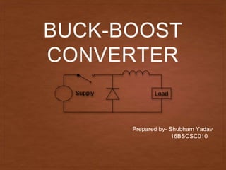
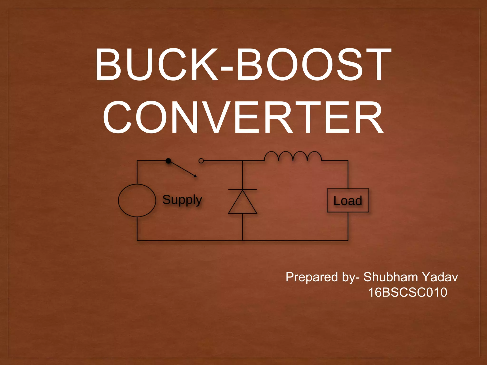
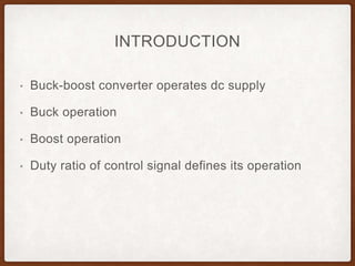
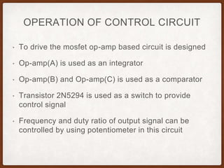
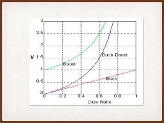
BUCK-BOOST
CONVERTER
Prepared by- Shubham Yadav
16BSCSC010
INTRODUCTION
• Buck-boost converter operates dc supply
• Buck operation
• Boost operation
• Duty ratio of control signal defines its operation
OPERATION OF CONTROL CIRCUIT
• To drive the mosfet op-amp based circuit is designed
• Op-amp(A) is used as an integrator
• Op-amp(B) and Op-amp(C) is used as a comparator
• Transistor 2N5294 is used as a switch to provide
control signal
• Frequency and duty ratio of output signal can be
controlled by using potentiometer in this circuit
• Output waveform of Op-amp(A)
• Output waveform of Op-amp(B)
• Output waveform of control circuit
POWER CIRCUIT
OPERATION OF POWER CIRCUIT
• Step 1: when mosfet is ON
• Voltage across inductor L is equal to V (source voltage)
• Step 2: When mofset is OFF
• Voltage across inductor L is equal to Vo (in reverse
direction)
• Here output voltage developed across load is Vo
• Step 3: when mosfet is ON in next cycle
Load is isolated from voltage source
In this case charged capacitor across load will
maintain voltage across load
DUTY RATIO
• Duty ratio D is defined as Ton/T
Here, Ton=ON time
T= time period of gate signal
• D= Ton/T
Ton=DT
• T=Ton+Toff
Toff=(1-D)T
VOLTAGE ACROSS INDUCTOR
• When mosfet is ON, voltage across inductor is equal to source
voltage (V)
• When mosfet is OFF, voltage across inductor is equal to output
voltage (V)
• As average voltage across inductor is zero
Hence,
V*D*T=Vo*(1-D)*T
Vo=V* D/1-D
• This equation shows that output voltage depends on
duty ratio(D)
• For buck operation
D=0 to 0.5
• For boost operation
D=0.5 to 1
APPLICATION
• Used in many industrial applications such as subway
cars, trolly buses, battery operated vehicles, battery
charging etc.
• To provide smooth control on output, high efficiency,
fast response and regeneration.
• To provide efficient control on dc motor operation
• To provide long life and less maintenance due to
absence of moving parts.
THANK YOU

Buck boost converter

  • 1.
  • 2.
    INTRODUCTION • Buck-boost converteroperates dc supply • Buck operation • Boost operation • Duty ratio of control signal defines its operation
  • 3.
    OPERATION OF CONTROLCIRCUIT • To drive the mosfet op-amp based circuit is designed • Op-amp(A) is used as an integrator • Op-amp(B) and Op-amp(C) is used as a comparator • Transistor 2N5294 is used as a switch to provide control signal • Frequency and duty ratio of output signal can be controlled by using potentiometer in this circuit
  • 4.
    • Output waveformof Op-amp(A) • Output waveform of Op-amp(B) • Output waveform of control circuit
  • 5.
  • 6.
    OPERATION OF POWERCIRCUIT • Step 1: when mosfet is ON • Voltage across inductor L is equal to V (source voltage)
  • 7.
    • Step 2:When mofset is OFF • Voltage across inductor L is equal to Vo (in reverse direction) • Here output voltage developed across load is Vo
  • 8.
    • Step 3:when mosfet is ON in next cycle Load is isolated from voltage source In this case charged capacitor across load will maintain voltage across load
  • 9.
    DUTY RATIO • Dutyratio D is defined as Ton/T Here, Ton=ON time T= time period of gate signal • D= Ton/T Ton=DT • T=Ton+Toff Toff=(1-D)T
  • 10.
    VOLTAGE ACROSS INDUCTOR •When mosfet is ON, voltage across inductor is equal to source voltage (V) • When mosfet is OFF, voltage across inductor is equal to output voltage (V) • As average voltage across inductor is zero Hence, V*D*T=Vo*(1-D)*T Vo=V* D/1-D
  • 11.
    • This equationshows that output voltage depends on duty ratio(D) • For buck operation D=0 to 0.5 • For boost operation D=0.5 to 1
  • 13.
    APPLICATION • Used inmany industrial applications such as subway cars, trolly buses, battery operated vehicles, battery charging etc. • To provide smooth control on output, high efficiency, fast response and regeneration. • To provide efficient control on dc motor operation • To provide long life and less maintenance due to absence of moving parts.
  • 14.