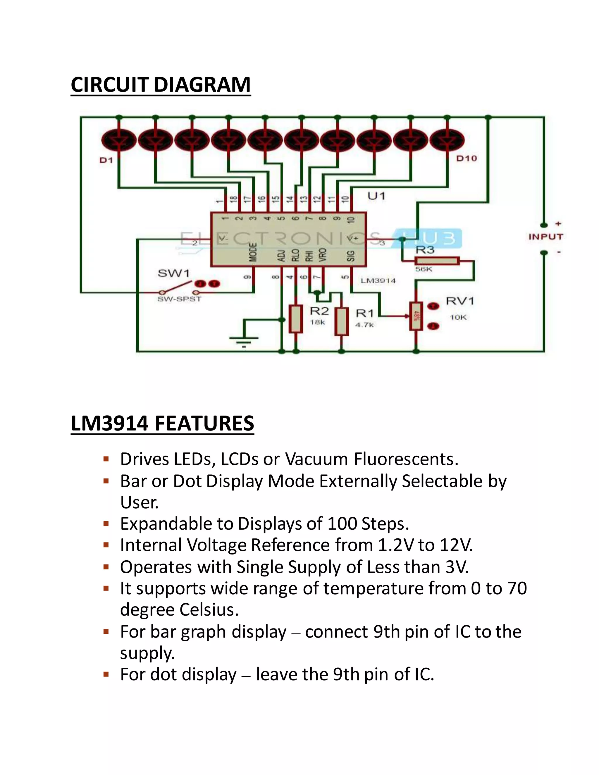
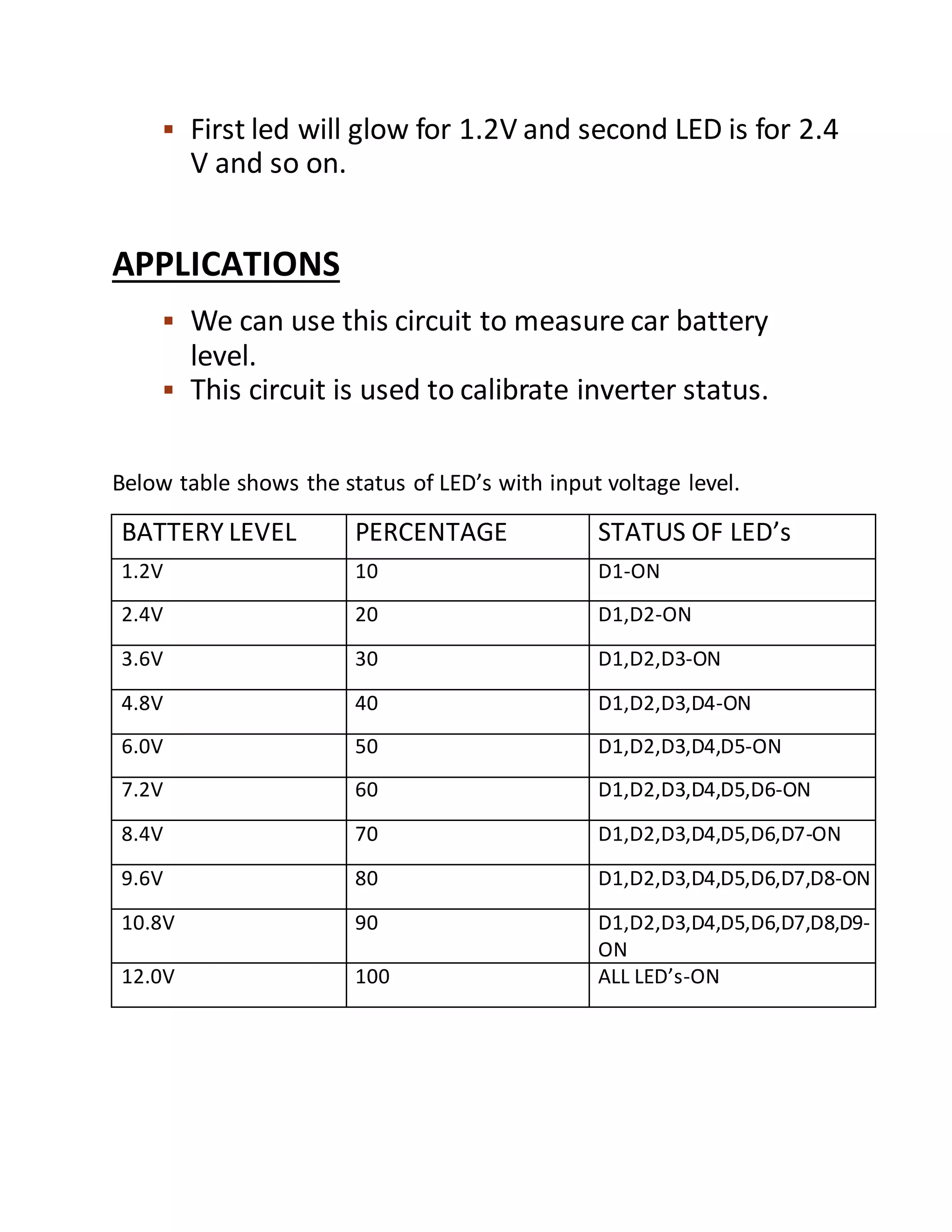
It is a battery level indicator program which tells the level of the battery how much it is charged. It includes the proteus pics of the program. I tells the working of the circuit.
1. BATTERY LEVEL INDICATOR
Battery level indicator indicates the status of the
battery just by glowing LED’s. For examplesix LED’s
are glowing means battery capacity 60% remains.
This article explains you how to design battery level
indicator. By using this circuit, we can increase the
lifetime of battery.
This circuit is designed based on LM3914 IC
(Integrated chip). This IC is LED dot/bar display
driver.
The heart of this battery level indicator circuit is
LM3914 IC. . In this circuit there is no need of
resistors in series with LED’s because current is
regulated by the IC.
COMPONENTS
LM3914 IC
LED’s -10
Switch
Resistors -18k,4.7k, 56k
Potentiometer – 10k
12V battery
Connecting wires
2. CIRCUIT DIAGRAM
LM3914 FEATURES
Drives LEDs, LCDs or Vacuum Fluorescents.
Bar or Dot Display Mode Externally Selectable by
User.
Expandable to Displays of 100 Steps.
Internal Voltage Reference from 1.2V to 12V.
Operates with Single Supply of Less than 3V.
It supports wide range of temperature from 0 to 70
degree Celsius.
For bar graph display – connect 9th pin of IC to the
supply.
For dot display – leave the 9th pin of IC.
3. CIRCUIT DESIGN
In this circuit LED’s (D1-D10)displays the capacity
of the battery in either dot mode or display mode.
This mode is selected by the external switch sw1
which is connected to 9th pin of IC. 6th and 7th
pins of IC are connected to the ground through a
resistor. This resistor controls the brightness of
LED’s. Here resistor R3 and POT RV1 forms
potential divider circuit. Here pot RV1 is used for
calibration. There is no need of any external power
supply to this circuit.
We can also connect different color LED’s to
indicate the status. Connect D1 to D3 red LED’s
which indicates shut down stage of your battery
and use D8-D10 green color LED’s which indicates
80 to 100 percentage of the battery and use yellow
color for remaining.
HOW TO OPERATE BATTERY LEVEL INDICATOR
CIRCUIT?
Connect 12V DC battery to the input.
Now adjust the pot RV1 so that LED D1 just starts
glowing.
Now increase the input Dc voltage slowly and
observe the LED’s
4. First led will glow for 1.2V and second LED is for 2.4
V and so on.
APPLICATIONS
We can use this circuit to measure car battery
level.
This circuit is used to calibrate inverter status.
Below table shows the status of LED’s with input voltage level.
BATTERY LEVEL PERCENTAGE STATUS OF LED’s
1.2V 10 D1-ON
2.4V 20 D1,D2-ON
3.6V 30 D1,D2,D3-ON
4.8V 40 D1,D2,D3,D4-ON
6.0V 50 D1,D2,D3,D4,D5-ON
7.2V 60 D1,D2,D3,D4,D5,D6-ON
8.4V 70 D1,D2,D3,D4,D5,D6,D7-ON
9.6V 80 D1,D2,D3,D4,D5,D6,D7,D8-ON
10.8V 90 D1,D2,D3,D4,D5,D6,D7,D8,D9-
ON
12.0V 100 ALL LED’s-ON