Downloaded 234 times


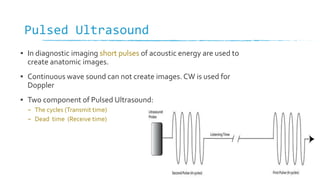
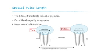
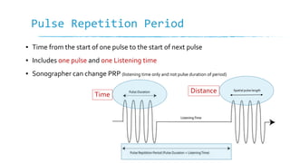


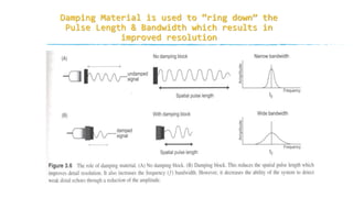
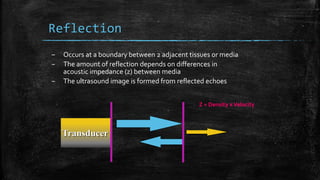


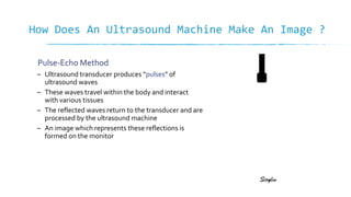
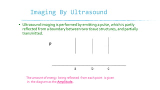
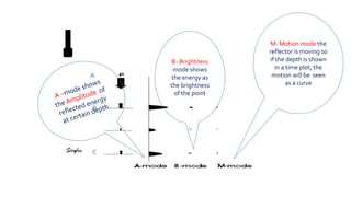
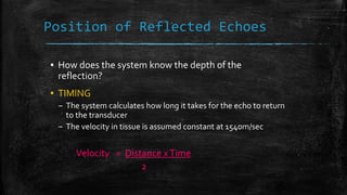
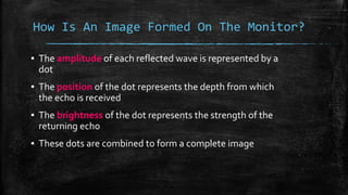


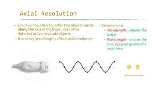
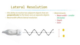
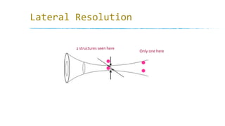
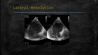
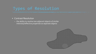


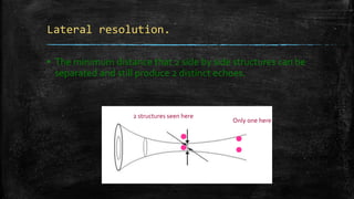


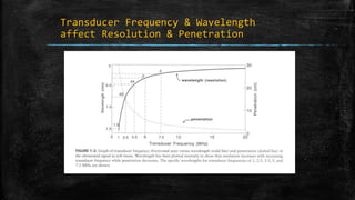


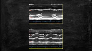

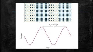


Ultrasound imaging relies on pulses of sound waves being emitted into the body and reflected echoes being received. The timing and amplitude of echoes are used to determine the position and brightness values of pixels in the ultrasound image. Image resolution depends on factors like wavelength, pulse length, beam width, and sweep speed, with shorter/smaller values allowing better separation of objects. Axial resolution relates to separation along the beam axis, lateral resolution to separation perpendicular to the beam, and temporal resolution to locating moving structures over time.


