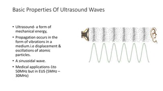
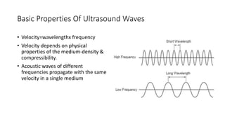
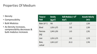
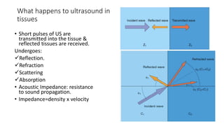
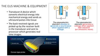
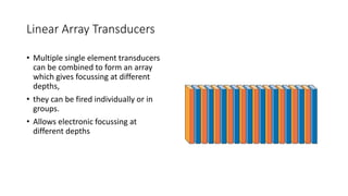
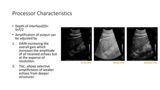
BASIC PHYSICS & SETTING OF
EUS SYSTEM
MR.PRIYARANJAN DAS (OLYMPUS)
Basic Properties Of Ultrasound Waves
• Ultrasound- a form of
mechanical energy,
• Propagation occurs in the
form of vibrations in a
medium.i.e displacement &
oscillations of atomic
particles.
• A sinusoidal wave.
• Medical applications-1to
50MHz but in EUS (5MHz –
30MHz)
Basic Properties Of Ultrasound Waves
• Velocity=wavelengthx frequency
• Velocity depends on physical
properties of the medium-density &
compressibility.
• Acoustic waves of different
frequencies propagate with the same
velocity in a single medium
Properties Of Medium
• Density
• Compressibility
• Bulk Modulus
• As Density increases,
compressibility decreases &
bulk modulus increases
What happens to ultrasound in
tissues
• Short pulses of US are
transmitted into the tissue &
reflected tissues are received.
Undergoes:
Reflection.
Refraction
Scattering
Absorption
• Acoustic Impedance: resistance
to sound propagation.
• Impedance=density x velocity
SCATTERING
• Scattering: occurs when US wave
interacts with small components in
tissue that are smaller than the
wavelength than incident waves and
different impedance values.
• Eg: individual cells, fat, collagen
• Responsible for different echotextures
of organs.
• Fat: high scattering; appears brighter,
due to multiple reflections
THE EUS MACHINE & EQUIPMENT
• Transducer:A device which
converts electrical energy into
mechanical energy and sends as
ultrsound pulses into tissue
• The back received signals are
picked up by the receiver built
in the transducer and sent to
processor which generates real
time images.
Linear Array Transducers
• Multiple single element transducers
can be combined to form an array
which gives focussing at different
depths,
• they can be fired individually or in
groups.
• Allows electronic focussing at
different depths
Processor Characteristics
• Depth of interface(D)=
VxT/2
• Amplification of output can
be adjusted by
1. GAIN-increasing the
overall gain which
increases the amplitude
of all received echoes but
at the expense of
resolution.
2. TGC: allows selective
amplifictaion of weaker
echoes from deeper
structures
IMAGING PRINCIPLES
RESOLUTION
• SPATIAL (X-axis -Axial, Y-axis - Lateral & Azimuthal Angle – Z-axis which is
Manufacturer dependent and fixed)
• TEMPORAL (Depends on FR, FW, Depth) – Function of time.
• CONTRAST
8-Bit Processor(256 shades of grey viz. as Dynamic Range.
CT has 10-Bit processing so gives higher resolution of B-Mode Imaging.
IMAGING PRINCIPLES
• RESOLUTION:
• Axial: smallest seperation
distance between two
objects that can be detected
along the beam.
• Determined by spatial pulse
length(SPL)-the length of
time the ultrasound pulse
occupies in space
• SPL =velocity/frequency x n.
• The limit of axial resolution is
SPL/2.
High Vs Low Frequency
IMAGING PRINCIPLES
• RESOLUTION:
• Lateral:
• Ability to discriminate
between two objects in a
perpendicular plane to that
of beam
• Depends on focusing of the
transducer;highly focused
transducer has narrow beam
width
Scanning
• A Mode Scan: Amplitude
Mode gives radiofrequency
wave patterns.
• Rarely used clinically.
• Forms the basis for other
modes.
• B Mode:-Brightness mode.
• Created by processing a
series of A mode signals-
resulting in a compound B
mode image.
DOPPLER
• Is used to identify objects that are
in motion relative to transducer.
• An object in motion will reflect a
wave that is of different
frequency; this is called doppler
shift.;this depends on velocity of
moving object.
• Greatest shifts detected when
transducer is aligned to flow
direction(Cos0 or Cos180)
Doppler
• Continuous doppler is used for recording high
velocities
• Pulse doppler is used for depth acuity
• Color doppler is like pulse doppler.
• Blood flow towards the transducer-Red.
• Flow away from the transducer-Blue.
• High velocities-turblant flow-green hue-mosaic
pattern
• Power doppler: determines the strength of doppler
signal discards info on velocity or direction.
• H-Flow : most sensitive for detecting blood flow
(Minute blood vessels visualization possible near
pancreatic region for better ROI targeting to collect
FNB/FNAC through EUS needle)
Imaging Artifacts
• Reverberation: Single transmitted
pulse undergoes multiple reflections
from a strong reflector,received by
transducer-reflected back.
• Identified by equal spacing between
hyperechoic bands
Reverberation Artifact
Acoustic Shadowing
• Large impedance encounter
• Majority is reflected and no
echo is detected beyond the
interface.
• Useful in detecting
calcifications.
Acoustic Shadowing
• Also seen due to refraction at a
boundary between tissue with
different velocities.-tumor or
cyst.
• Because of bending of the beam
some amount of tissue is not
visible-
Reflection-Mirror Imaging
• Occurs when imaging
near an airwater
interface such as
lumen partially filled
with water.
• Becuz of significant
impedance mismatch
the transmitted pulse
is reflected multiple
times.
• can be avoided by
removing air
Through Transmission
• Enhancement of a structure
beyond a fluid filled structure
such as cyst.
• Due to less attenuation of the
wave as it passes through the
cyst.
• Seen with cyst or blood vessel.
Tangential Scanning
• To accurately measure the
thickness of a strucure the
transducer should be
perpendicular to the structure.
• Tangential scanning results in over
estimation of thickness.
• Importance lies in staging of GI
cancers
• On radial EUS this can be
identified.
• Tip maneuvering should be done
Side Lobe Artifacts
• Off axis secondary projections of US
beam.
• They are of low intensities but still can
produce weak echoes but usually are
obscured by on axis high intensity beam.
• But while viewing anechoic structures
these atrifacts become manifest.
• Disappears with repositioning the
transducer.
Harmonics utility is helpful to eliminate
the side lobe artifacts or reverberation
by increasing SNR which results in
increasing resolution of B-Mode imaging
drastically.
BASICS OF EUS PHYSICS.pptx

BASICS OF EUS PHYSICS.pptx

  • 1.
    BASIC PHYSICS &SETTING OF EUS SYSTEM MR.PRIYARANJAN DAS (OLYMPUS)
  • 2.
    Basic Properties OfUltrasound Waves • Ultrasound- a form of mechanical energy, • Propagation occurs in the form of vibrations in a medium.i.e displacement & oscillations of atomic particles. • A sinusoidal wave. • Medical applications-1to 50MHz but in EUS (5MHz – 30MHz)
  • 3.
    Basic Properties OfUltrasound Waves • Velocity=wavelengthx frequency • Velocity depends on physical properties of the medium-density & compressibility. • Acoustic waves of different frequencies propagate with the same velocity in a single medium
  • 4.
    Properties Of Medium •Density • Compressibility • Bulk Modulus • As Density increases, compressibility decreases & bulk modulus increases
  • 5.
    What happens toultrasound in tissues • Short pulses of US are transmitted into the tissue & reflected tissues are received. Undergoes: Reflection. Refraction Scattering Absorption • Acoustic Impedance: resistance to sound propagation. • Impedance=density x velocity
  • 6.
    SCATTERING • Scattering: occurswhen US wave interacts with small components in tissue that are smaller than the wavelength than incident waves and different impedance values. • Eg: individual cells, fat, collagen • Responsible for different echotextures of organs. • Fat: high scattering; appears brighter, due to multiple reflections
  • 7.
    THE EUS MACHINE& EQUIPMENT • Transducer:A device which converts electrical energy into mechanical energy and sends as ultrsound pulses into tissue • The back received signals are picked up by the receiver built in the transducer and sent to processor which generates real time images.
  • 8.
    Linear Array Transducers •Multiple single element transducers can be combined to form an array which gives focussing at different depths, • they can be fired individually or in groups. • Allows electronic focussing at different depths
  • 9.
    Processor Characteristics • Depthof interface(D)= VxT/2 • Amplification of output can be adjusted by 1. GAIN-increasing the overall gain which increases the amplitude of all received echoes but at the expense of resolution. 2. TGC: allows selective amplifictaion of weaker echoes from deeper structures
  • 10.
    IMAGING PRINCIPLES RESOLUTION • SPATIAL(X-axis -Axial, Y-axis - Lateral & Azimuthal Angle – Z-axis which is Manufacturer dependent and fixed) • TEMPORAL (Depends on FR, FW, Depth) – Function of time. • CONTRAST 8-Bit Processor(256 shades of grey viz. as Dynamic Range. CT has 10-Bit processing so gives higher resolution of B-Mode Imaging.
  • 11.
    IMAGING PRINCIPLES • RESOLUTION: •Axial: smallest seperation distance between two objects that can be detected along the beam. • Determined by spatial pulse length(SPL)-the length of time the ultrasound pulse occupies in space • SPL =velocity/frequency x n. • The limit of axial resolution is SPL/2.
  • 12.
    High Vs LowFrequency
  • 13.
    IMAGING PRINCIPLES • RESOLUTION: •Lateral: • Ability to discriminate between two objects in a perpendicular plane to that of beam • Depends on focusing of the transducer;highly focused transducer has narrow beam width
  • 14.
    Scanning • A ModeScan: Amplitude Mode gives radiofrequency wave patterns. • Rarely used clinically. • Forms the basis for other modes. • B Mode:-Brightness mode. • Created by processing a series of A mode signals- resulting in a compound B mode image.
  • 15.
    DOPPLER • Is usedto identify objects that are in motion relative to transducer. • An object in motion will reflect a wave that is of different frequency; this is called doppler shift.;this depends on velocity of moving object. • Greatest shifts detected when transducer is aligned to flow direction(Cos0 or Cos180)
  • 16.
    Doppler • Continuous doppleris used for recording high velocities • Pulse doppler is used for depth acuity • Color doppler is like pulse doppler. • Blood flow towards the transducer-Red. • Flow away from the transducer-Blue. • High velocities-turblant flow-green hue-mosaic pattern • Power doppler: determines the strength of doppler signal discards info on velocity or direction. • H-Flow : most sensitive for detecting blood flow (Minute blood vessels visualization possible near pancreatic region for better ROI targeting to collect FNB/FNAC through EUS needle)
  • 17.
    Imaging Artifacts • Reverberation:Single transmitted pulse undergoes multiple reflections from a strong reflector,received by transducer-reflected back. • Identified by equal spacing between hyperechoic bands
  • 18.
  • 19.
    Acoustic Shadowing • Largeimpedance encounter • Majority is reflected and no echo is detected beyond the interface. • Useful in detecting calcifications.
  • 20.
    Acoustic Shadowing • Alsoseen due to refraction at a boundary between tissue with different velocities.-tumor or cyst. • Because of bending of the beam some amount of tissue is not visible-
  • 21.
    Reflection-Mirror Imaging • Occurswhen imaging near an airwater interface such as lumen partially filled with water. • Becuz of significant impedance mismatch the transmitted pulse is reflected multiple times. • can be avoided by removing air
  • 22.
    Through Transmission • Enhancementof a structure beyond a fluid filled structure such as cyst. • Due to less attenuation of the wave as it passes through the cyst. • Seen with cyst or blood vessel.
  • 23.
    Tangential Scanning • Toaccurately measure the thickness of a strucure the transducer should be perpendicular to the structure. • Tangential scanning results in over estimation of thickness. • Importance lies in staging of GI cancers • On radial EUS this can be identified. • Tip maneuvering should be done
  • 24.
    Side Lobe Artifacts •Off axis secondary projections of US beam. • They are of low intensities but still can produce weak echoes but usually are obscured by on axis high intensity beam. • But while viewing anechoic structures these atrifacts become manifest. • Disappears with repositioning the transducer. Harmonics utility is helpful to eliminate the side lobe artifacts or reverberation by increasing SNR which results in increasing resolution of B-Mode imaging drastically.