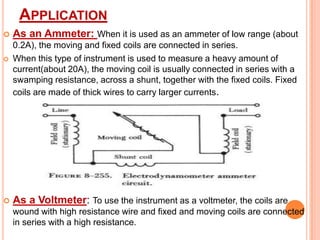
Downloaded 1,700 times
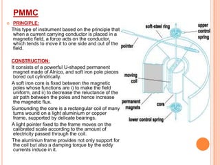
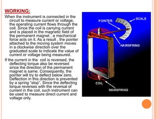
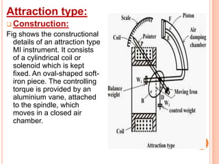
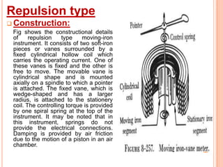


This document discusses electrical and electronics measurements. It describes the process of measurement by comparing unknown values to known standards. It then discusses key characteristics of instruments used for measurement, including calibration, accuracy, precision, repeatability, reproducibility, drift, span, sensitivity, resolution, and dead zone. The document also covers types of errors in measurement, including static, mistakes, systematic, and random errors. It lists sources of error and types of instruments, including absolute, secondary, indicating, recording, and integrating instruments. Finally, it provides details on permanent magnet moving coil (PMMC) and moving iron (MI) types of indicating instruments.


![ELECTRICAL MEASUREMENT & MEASURING INSTRUMENTS [Emmi- (NEE-302) -unit-1]](https://cdn.slidesharecdn.com/ss_thumbnails/emmi-nee-302-unit-1-170607090405-thumbnail.jpg?width=640&height=640&fit=bounds)