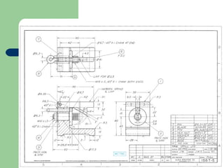
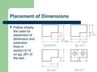
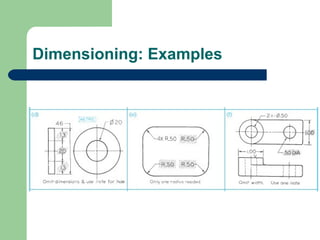
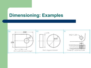
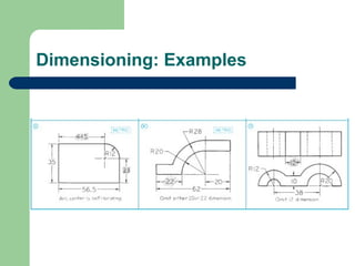
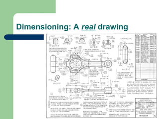
Standard Practice for
Dimensioning Drawings
Introduction to
Mechanical Engineering
Fall 2004
Created by:
P.M. Larochelle
Dimensions
 Dimensions

are used to describe the sizes
and relationships between features in your
drawing.
 Dimensions are used to manufacture parts
and to inspect the the resulting parts to
determine if they meet the drawing’s
specifications.
Dimensions
 Drawings

with dimensions and notes often
serve as manufacturing or construction
documents and legal contracts.
 ASME Y14.5 is the current geometric
dimensioning and tolerancing standard.
Dimensions
 Definition:

Dimensions are the distances,
angles, and notes that define the geometry
and manufacturing of the object.
 Do not give superfluous dimensions
–

–

Only those dimensions that are needed to
manufacture and inspect the object are to be
included on the drawing
Do not include dimensions just because they are
needed to produce the drawing
Dimensioning
Good Dimensioning
 The
–
–
–
–

keys to good dimensioning are:

Choice of dimensions
Placement of dimensions
Technique of dimensioning
Specifying dimension tolerances
Choice of Dimensions


The dimensions you specify define how the object is
manufactured:
–



Dimension first for function and then review seeking
improvements for production/manufacturing purposes such
as manufacturability, inspection, etc.

Do not give superfluous dimensions
–
–

Only those dimensions that are needed to manufacture and
inspect the object are to be included on the drawing
Each dimension should appear only once; do not repeat
dimensions in different views.
Placement of Dimensions
 Follow

accepted standards so that
dimensions are legible, easy to find, and
easy to interpret.
 The spacing of dimensions lines must be
uniform throughout the drawing.
Placement of Dimensions
 Do’s
–
–
–
–

& Don’t’s

Avoid dimensions on the object itself
Avoid dimensioning to hidden lines
Don’t float dimensions
Do group dimensions around a central view
Placement of Dimensions


Follow closely
the rules for
placement of
dimension and
extension
lines in
section 9.14
on pg. 291 of
the text.
Technique of Dimensioning
 Follow

accepted standards & practices for
the appearance of lines, spacing of
dimension lines, size of arrowheads, etc. so
that others may correctly interpret your
drawing.
Lines Used in Dimensioning
A

dimension line
is a thin, dark,
solid line
terminated by
arrowheads that
indicate the
direction and
extent of a
dimension.
Lines Used in Dimensioning
 An

extension line is a thin, dark, solid line that
extends from a point on the drawing to its
associated dimension line.
–

A gap of ~1.5 mm should be left between the
extension line and the point on the part.
Lines Used in Dimensioning
A

center line is a thin, dark, solid line that
alternates long and short dashes to locate holes
and other symmetrical features.
Lines Used in Dimensioning
 Arrowheads

are used to indicate the extent of a
dimension. They should be uniform in size &
style throughout the drawing.
Lines Used in Dimensioning


An leader is a thin, solid line directing attention to a note
or dimension. A leader starts with an arrow or dot:
–
–

Use an arrow when the leader can point to a specific line in the
drawing such as the edge of a surface
Use a dot when the leader is locating a feature within the outline
of the part
Dimension Tolerances


A tolerance is required for every dimension on a drawing.
Definition: a tolerance is the total amount that the feature
on the actual part is allowed to vary from what is
specified by the dimension.
–

A general tolerance applicable to most dimensions can be
specified in the title block.


–

Example: “All tolerances +/- 0.01 inches unless otherwise noted”.

A tolerance for a particular dimension may be specified by limit
dimensions or plus and minus dimensions.


Example: “1.500 +/-.003” or “1.252/1.248”
Dimension Tolerances: Examples
Dimension Tolerances
 The
–
–
–

purpose of dimension tolerances:

Allows a range of acceptable variability on the
dimensions of a part
Assures that parts interchanged between assemblies
will fit properly
Allowing parts be manufactured to prescribed
tolerances rather than exact dimensions permits
efficient and economical manufacturing. In general:
high precision means high cost!
Dimension Tolerances
 Tolerance

stacking is to be avoided by
dimensioning with respect to a datum.
Do’s & Don’ts of Dimensioning




Do not trust the automatic creation & placement of
dimensions done for you by CAD software.
Review & use the list in section 9.43 pg. 318 of the
text for every dimensioned drawing you create:
1.
2.
3.
4.

Each dimension should be given clearly so that it can be
interpreted only one way
Dimensions should not be duplicated
Dimensions should be given so that the machinist will not
have to calculate, scale, or assume any dimensions.
The list goes on to #57!
Dimensioning: Examples
Dimensioning: A real drawing
Dimensioning: Homework


Do Figure #9.71 on page 328 of the text.
Create a sketch with metric dimensions on
green engineering paper. Due before
lecture begins on Wednesday October 20th.
References
 Chapters

9 of Modern Graphics
Communication by Giesecke, Mitchell,
Spencer, Hill, Dygdon, Novak, and Lockhard,
3rd edition. Prentice-Hall, 2004.
 Technical Drawing by Giesecke, Mitchell,
Spencer, Hill, Dygdon, and Novak, 9th edition.
Macmillan, 1991.

Dimensioning 1

  • 1.
    Standard Practice for DimensioningDrawings Introduction to Mechanical Engineering Fall 2004 Created by: P.M. Larochelle
  • 2.
    Dimensions  Dimensions are usedto describe the sizes and relationships between features in your drawing.  Dimensions are used to manufacture parts and to inspect the the resulting parts to determine if they meet the drawing’s specifications.
  • 3.
    Dimensions  Drawings with dimensionsand notes often serve as manufacturing or construction documents and legal contracts.  ASME Y14.5 is the current geometric dimensioning and tolerancing standard.
  • 4.
    Dimensions  Definition: Dimensions arethe distances, angles, and notes that define the geometry and manufacturing of the object.  Do not give superfluous dimensions – – Only those dimensions that are needed to manufacture and inspect the object are to be included on the drawing Do not include dimensions just because they are needed to produce the drawing
  • 5.
  • 6.
    Good Dimensioning  The – – – – keysto good dimensioning are: Choice of dimensions Placement of dimensions Technique of dimensioning Specifying dimension tolerances
  • 7.
    Choice of Dimensions  Thedimensions you specify define how the object is manufactured: –  Dimension first for function and then review seeking improvements for production/manufacturing purposes such as manufacturability, inspection, etc. Do not give superfluous dimensions – – Only those dimensions that are needed to manufacture and inspect the object are to be included on the drawing Each dimension should appear only once; do not repeat dimensions in different views.
  • 8.
    Placement of Dimensions Follow accepted standards so that dimensions are legible, easy to find, and easy to interpret.  The spacing of dimensions lines must be uniform throughout the drawing.
  • 9.
    Placement of Dimensions Do’s – – – – & Don’t’s Avoid dimensions on the object itself Avoid dimensioning to hidden lines Don’t float dimensions Do group dimensions around a central view
  • 10.
    Placement of Dimensions  Followclosely the rules for placement of dimension and extension lines in section 9.14 on pg. 291 of the text.
  • 11.
    Technique of Dimensioning Follow accepted standards & practices for the appearance of lines, spacing of dimension lines, size of arrowheads, etc. so that others may correctly interpret your drawing.
  • 12.
    Lines Used inDimensioning A dimension line is a thin, dark, solid line terminated by arrowheads that indicate the direction and extent of a dimension.
  • 13.
    Lines Used inDimensioning  An extension line is a thin, dark, solid line that extends from a point on the drawing to its associated dimension line. – A gap of ~1.5 mm should be left between the extension line and the point on the part.
  • 14.
    Lines Used inDimensioning A center line is a thin, dark, solid line that alternates long and short dashes to locate holes and other symmetrical features.
  • 15.
    Lines Used inDimensioning  Arrowheads are used to indicate the extent of a dimension. They should be uniform in size & style throughout the drawing.
  • 16.
    Lines Used inDimensioning  An leader is a thin, solid line directing attention to a note or dimension. A leader starts with an arrow or dot: – – Use an arrow when the leader can point to a specific line in the drawing such as the edge of a surface Use a dot when the leader is locating a feature within the outline of the part
  • 17.
    Dimension Tolerances  A toleranceis required for every dimension on a drawing. Definition: a tolerance is the total amount that the feature on the actual part is allowed to vary from what is specified by the dimension. – A general tolerance applicable to most dimensions can be specified in the title block.  – Example: “All tolerances +/- 0.01 inches unless otherwise noted”. A tolerance for a particular dimension may be specified by limit dimensions or plus and minus dimensions.  Example: “1.500 +/-.003” or “1.252/1.248”
  • 18.
  • 19.
    Dimension Tolerances  The – – – purposeof dimension tolerances: Allows a range of acceptable variability on the dimensions of a part Assures that parts interchanged between assemblies will fit properly Allowing parts be manufactured to prescribed tolerances rather than exact dimensions permits efficient and economical manufacturing. In general: high precision means high cost!
  • 20.
    Dimension Tolerances  Tolerance stackingis to be avoided by dimensioning with respect to a datum.
  • 21.
    Do’s & Don’tsof Dimensioning   Do not trust the automatic creation & placement of dimensions done for you by CAD software. Review & use the list in section 9.43 pg. 318 of the text for every dimensioned drawing you create: 1. 2. 3. 4. Each dimension should be given clearly so that it can be interpreted only one way Dimensions should not be duplicated Dimensions should be given so that the machinist will not have to calculate, scale, or assume any dimensions. The list goes on to #57!
  • 22.
  • 23.
  • 24.
  • 25.
  • 26.
  • 27.
  • 28.
  • 29.
  • 30.
  • 31.
  • 32.
  • 33.
    Dimensioning: Homework  Do Figure#9.71 on page 328 of the text. Create a sketch with metric dimensions on green engineering paper. Due before lecture begins on Wednesday October 20th.
  • 34.
    References  Chapters 9 ofModern Graphics Communication by Giesecke, Mitchell, Spencer, Hill, Dygdon, Novak, and Lockhard, 3rd edition. Prentice-Hall, 2004.  Technical Drawing by Giesecke, Mitchell, Spencer, Hill, Dygdon, and Novak, 9th edition. Macmillan, 1991.