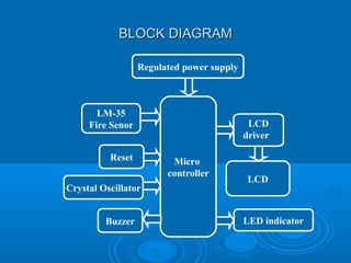
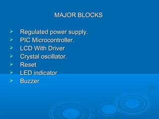
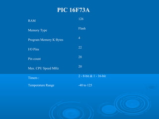
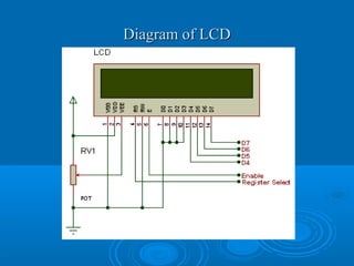
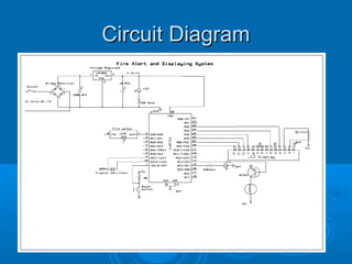
AVOIDANCE OF FIRE ACCIDENTS ON TRAINSAVOIDANCE OF FIRE ACCIDENTS ON TRAINS
IntroductionIntroduction
 The trains are moderate vehicles used for transporting peopleThe trains are moderate vehicles used for transporting people
and goodsand goods
 Mostly, the people prefer the train journey for longer distanceMostly, the people prefer the train journey for longer distance
as it is cheaper.as it is cheaper.
 And our Indian Railway network is the world’s second largestAnd our Indian Railway network is the world’s second largest
Railway network.Railway network.
 But fire accidents in trains are among the most serious disastersBut fire accidents in trains are among the most serious disasters
to human lives and to the property of governmentto human lives and to the property of government
 Because the only precautionary warnings about the fire in eachBecause the only precautionary warnings about the fire in each
compartment are The notices showing "Do not smoke", "Do notcompartment are The notices showing "Do not smoke", "Do not
carry inflammable material“carry inflammable material“
 Hence we proposed our project to overcome these problems.Hence we proposed our project to overcome these problems.
BLOCK DIAGRAMBLOCK DIAGRAM
Micro
controller
LCD
LED indicator
Crystal Oscillator
LCD
driver
Regulated power supply
Reset
LM-35
Fire Senor
Buzzer
MAJOR BLOCKSMAJOR BLOCKS
 Regulated power supply.Regulated power supply.
 PIC Microcontroller.PIC Microcontroller.
 LCD With DriverLCD With Driver
 Crystal oscillator.Crystal oscillator.
 ResetReset
 LED indicatorLED indicator
 BuzzerBuzzer
 PIC is a family of Harvard architecture microcontrollers madePIC is a family of Harvard architecture microcontrollers made
by Microchip Technology, derived from the PIC1640by Microchip Technology, derived from the PIC1640
originally developed by General Instrument's Microelectronicsoriginally developed by General Instrument's Microelectronics
Division. The name PIC initially referred to "PeripheralDivision. The name PIC initially referred to "Peripheral
InterfaceInterface Controller".Controller".
 A PIC's instructions vary from about 35 instructions for theA PIC's instructions vary from about 35 instructions for the
low-end PICs to over 80 instructions for the high-end PICs.low-end PICs to over 80 instructions for the high-end PICs.
The instruction set includes instructions to perform a varietyThe instruction set includes instructions to perform a variety
of operations on registers directly, the accumulator and aof operations on registers directly, the accumulator and a
literal constant or the accumulator and a register, as well as forliteral constant or the accumulator and a register, as well as for
conditional execution, and program branching.conditional execution, and program branching.
ABOUT PIC MICROCONTROLLER
PIC CONTROLLERPIC CONTROLLER
 PIC microcontroller has four optional clock sources.PIC microcontroller has four optional clock sources.
 Low power crystalLow power crystal
 Mid range crystalMid range crystal
 High range crystalHigh range crystal
 RC oscillator (low cost).RC oscillator (low cost).
 Programmable timers and on-chip ADC.Programmable timers and on-chip ADC.
 Up to 12 independent interrupt sources.Up to 12 independent interrupt sources.
 Powerful output pin control (25 mA (max.) currentPowerful output pin control (25 mA (max.) current
sourcing capability per pin.)sourcing capability per pin.)
 EPROM/OTP/ROM/Flash memory option.EPROM/OTP/ROM/Flash memory option.
 I/O port expansion capability.I/O port expansion capability.
PIC 16F73A
RAM
126
Memory Type
Flash
Program Memory K Bytes
4
I/O Pins
22
Pin count
28
Max. CPU Speed MHz
20
Timers :
2 - 8-bit & 1 - 16-bit
Temperature Range -40 to 125
RISC instruction set with around 35 instructions _9 Digital I/O ports
On-chip timer with 8-bit prescaler.
Power-on reset
Watchdog timer
Power saving SLEEP mode
Direct, indirect, and relative addressing modes
External clock interface
RAM data memory
EPROM (or OTP) program memory
GENERAL FEATURES:
REGULATED POWER SUPPLYREGULATED POWER SUPPLY
The major blocks of power supply are given belowThe major blocks of power supply are given below
 TransformerTransformer
 RectifierRectifier
 FilterFilter
 7805 voltage regulator7805 voltage regulator
LCD DISPLAYLCD DISPLAY
LCD Background:LCD Background:
 One of the most common devices attached to a microOne of the most common devices attached to a micro
controller is an LCD display. Some of the mostcontroller is an LCD display. Some of the most
common LCD’s connected to the manycommon LCD’s connected to the many
microcontrollers are 16x2 and 20x2 displays. Thismicrocontrollers are 16x2 and 20x2 displays. This
means 16 characters per line by 2 lines and 20means 16 characters per line by 2 lines and 20
characters per line by 2 lines, respectively.characters per line by 2 lines, respectively.
Diagram of LCDDiagram of LCD
BUZZER
 A buzzer or beeper is an audio signaling device,
which may be mechanical, electromechanical,
or electronic.
 A buzzer can be operated on two principles.
1. piezo electric buzzer, it generates sound because of the
piezoelectric effect.
2. magnetic buzzer is based on the electromagnetic principle. In
this project we are going to use magnetic buzzer.
characteristics of buzzer circuit :
1. sound level -------------------70-95 dB
2. current consumption---------35-60 ma
3. resonant frequency---------- 1-3 khz
OSCILLATOROSCILLATOR
 An electronic oscillator is an electronic circuit
that produces a repetitive Electronic signal, often a sine wave
or a square wave.
 PIC micro controller internally having 4mhz clock frequency.
 We are giving the 20Mhz clock frequency as an external
source for increasing the system performance
LED INDICATORSLED INDICATORS
 Led indicators have a life of at least ten years and
consume 90 per cent less power than conventional indicators.
 Depending on the type of the materials (Ga,As,p) led will
gives the output in different colors (red, Yellow, green etc..)
 LED’s emitted low-intensity red light, but modern versions are
available across the visible, ultraviolet and infrared wavelengths,
with very high brightness.
 LED’s are used as indicator lamps in many devices, and are
increasingly used for lighting. Introduced as a practical electronic
component
RESET BUTTONRESET BUTTON
 The reset button is a button that when clicked, willThe reset button is a button that when clicked, will
clear all of the fields in the micro controller, andclear all of the fields in the micro controller, and
executes the instructions from the starting address.executes the instructions from the starting address.
 A switch placed between the digital input andA switch placed between the digital input and
ground will short the digital input to ground when itground will short the digital input to ground when it
is pressed. This means the voltage seen at the inputis pressed. This means the voltage seen at the input
will be high when the switch is open and low whenwill be high when the switch is open and low when
the switch is closed.the switch is closed.
Circuit DiagramCircuit Diagram
FEATURES OF THIS PROJECT
 It consumes very less powerIt consumes very less power
 User friendlyUser friendly
 High performanceHigh performance
 Low cost and very efficientLow cost and very efficient
Applications of the projectApplications of the project
This project can be used in real timeThis project can be used in real time
applications like trains, buses,applications like trains, buses,
homes and industries, etc……homes and industries, etc……
FUTURE SCOPEFUTURE SCOPE
 This project we can implemented byThis project we can implemented by
adding automatic water pumping systemadding automatic water pumping system
when fire will be detectedwhen fire will be detected
Avoidance of Fire accidents on Trains

Avoidance of Fire accidents on Trains

  • 1.
    AVOIDANCE OF FIREACCIDENTS ON TRAINSAVOIDANCE OF FIRE ACCIDENTS ON TRAINS
  • 2.
    IntroductionIntroduction  The trainsare moderate vehicles used for transporting peopleThe trains are moderate vehicles used for transporting people and goodsand goods  Mostly, the people prefer the train journey for longer distanceMostly, the people prefer the train journey for longer distance as it is cheaper.as it is cheaper.  And our Indian Railway network is the world’s second largestAnd our Indian Railway network is the world’s second largest Railway network.Railway network.  But fire accidents in trains are among the most serious disastersBut fire accidents in trains are among the most serious disasters to human lives and to the property of governmentto human lives and to the property of government  Because the only precautionary warnings about the fire in eachBecause the only precautionary warnings about the fire in each compartment are The notices showing "Do not smoke", "Do notcompartment are The notices showing "Do not smoke", "Do not carry inflammable material“carry inflammable material“  Hence we proposed our project to overcome these problems.Hence we proposed our project to overcome these problems.
  • 3.
    BLOCK DIAGRAMBLOCK DIAGRAM Micro controller LCD LEDindicator Crystal Oscillator LCD driver Regulated power supply Reset LM-35 Fire Senor Buzzer
  • 4.
    MAJOR BLOCKSMAJOR BLOCKS Regulated power supply.Regulated power supply.  PIC Microcontroller.PIC Microcontroller.  LCD With DriverLCD With Driver  Crystal oscillator.Crystal oscillator.  ResetReset  LED indicatorLED indicator  BuzzerBuzzer
  • 5.
     PIC isa family of Harvard architecture microcontrollers madePIC is a family of Harvard architecture microcontrollers made by Microchip Technology, derived from the PIC1640by Microchip Technology, derived from the PIC1640 originally developed by General Instrument's Microelectronicsoriginally developed by General Instrument's Microelectronics Division. The name PIC initially referred to "PeripheralDivision. The name PIC initially referred to "Peripheral InterfaceInterface Controller".Controller".  A PIC's instructions vary from about 35 instructions for theA PIC's instructions vary from about 35 instructions for the low-end PICs to over 80 instructions for the high-end PICs.low-end PICs to over 80 instructions for the high-end PICs. The instruction set includes instructions to perform a varietyThe instruction set includes instructions to perform a variety of operations on registers directly, the accumulator and aof operations on registers directly, the accumulator and a literal constant or the accumulator and a register, as well as forliteral constant or the accumulator and a register, as well as for conditional execution, and program branching.conditional execution, and program branching. ABOUT PIC MICROCONTROLLER
  • 6.
    PIC CONTROLLERPIC CONTROLLER PIC microcontroller has four optional clock sources.PIC microcontroller has four optional clock sources.  Low power crystalLow power crystal  Mid range crystalMid range crystal  High range crystalHigh range crystal  RC oscillator (low cost).RC oscillator (low cost).  Programmable timers and on-chip ADC.Programmable timers and on-chip ADC.  Up to 12 independent interrupt sources.Up to 12 independent interrupt sources.  Powerful output pin control (25 mA (max.) currentPowerful output pin control (25 mA (max.) current sourcing capability per pin.)sourcing capability per pin.)  EPROM/OTP/ROM/Flash memory option.EPROM/OTP/ROM/Flash memory option.  I/O port expansion capability.I/O port expansion capability.
  • 7.
    PIC 16F73A RAM 126 Memory Type Flash ProgramMemory K Bytes 4 I/O Pins 22 Pin count 28 Max. CPU Speed MHz 20 Timers : 2 - 8-bit & 1 - 16-bit Temperature Range -40 to 125
  • 8.
    RISC instruction setwith around 35 instructions _9 Digital I/O ports On-chip timer with 8-bit prescaler. Power-on reset Watchdog timer Power saving SLEEP mode Direct, indirect, and relative addressing modes External clock interface RAM data memory EPROM (or OTP) program memory GENERAL FEATURES:
  • 9.
    REGULATED POWER SUPPLYREGULATEDPOWER SUPPLY The major blocks of power supply are given belowThe major blocks of power supply are given below  TransformerTransformer  RectifierRectifier  FilterFilter  7805 voltage regulator7805 voltage regulator
  • 10.
    LCD DISPLAYLCD DISPLAY LCDBackground:LCD Background:  One of the most common devices attached to a microOne of the most common devices attached to a micro controller is an LCD display. Some of the mostcontroller is an LCD display. Some of the most common LCD’s connected to the manycommon LCD’s connected to the many microcontrollers are 16x2 and 20x2 displays. Thismicrocontrollers are 16x2 and 20x2 displays. This means 16 characters per line by 2 lines and 20means 16 characters per line by 2 lines and 20 characters per line by 2 lines, respectively.characters per line by 2 lines, respectively.
  • 11.
  • 12.
    BUZZER  A buzzeror beeper is an audio signaling device, which may be mechanical, electromechanical, or electronic.  A buzzer can be operated on two principles. 1. piezo electric buzzer, it generates sound because of the piezoelectric effect. 2. magnetic buzzer is based on the electromagnetic principle. In this project we are going to use magnetic buzzer. characteristics of buzzer circuit : 1. sound level -------------------70-95 dB 2. current consumption---------35-60 ma 3. resonant frequency---------- 1-3 khz
  • 13.
    OSCILLATOROSCILLATOR  An electronicoscillator is an electronic circuit that produces a repetitive Electronic signal, often a sine wave or a square wave.  PIC micro controller internally having 4mhz clock frequency.  We are giving the 20Mhz clock frequency as an external source for increasing the system performance
  • 14.
    LED INDICATORSLED INDICATORS Led indicators have a life of at least ten years and consume 90 per cent less power than conventional indicators.  Depending on the type of the materials (Ga,As,p) led will gives the output in different colors (red, Yellow, green etc..)  LED’s emitted low-intensity red light, but modern versions are available across the visible, ultraviolet and infrared wavelengths, with very high brightness.  LED’s are used as indicator lamps in many devices, and are increasingly used for lighting. Introduced as a practical electronic component
  • 15.
    RESET BUTTONRESET BUTTON The reset button is a button that when clicked, willThe reset button is a button that when clicked, will clear all of the fields in the micro controller, andclear all of the fields in the micro controller, and executes the instructions from the starting address.executes the instructions from the starting address.  A switch placed between the digital input andA switch placed between the digital input and ground will short the digital input to ground when itground will short the digital input to ground when it is pressed. This means the voltage seen at the inputis pressed. This means the voltage seen at the input will be high when the switch is open and low whenwill be high when the switch is open and low when the switch is closed.the switch is closed.
  • 16.
  • 17.
    FEATURES OF THISPROJECT  It consumes very less powerIt consumes very less power  User friendlyUser friendly  High performanceHigh performance  Low cost and very efficientLow cost and very efficient
  • 18.
    Applications of theprojectApplications of the project This project can be used in real timeThis project can be used in real time applications like trains, buses,applications like trains, buses, homes and industries, etc……homes and industries, etc……
  • 19.
    FUTURE SCOPEFUTURE SCOPE This project we can implemented byThis project we can implemented by adding automatic water pumping systemadding automatic water pumping system when fire will be detectedwhen fire will be detected