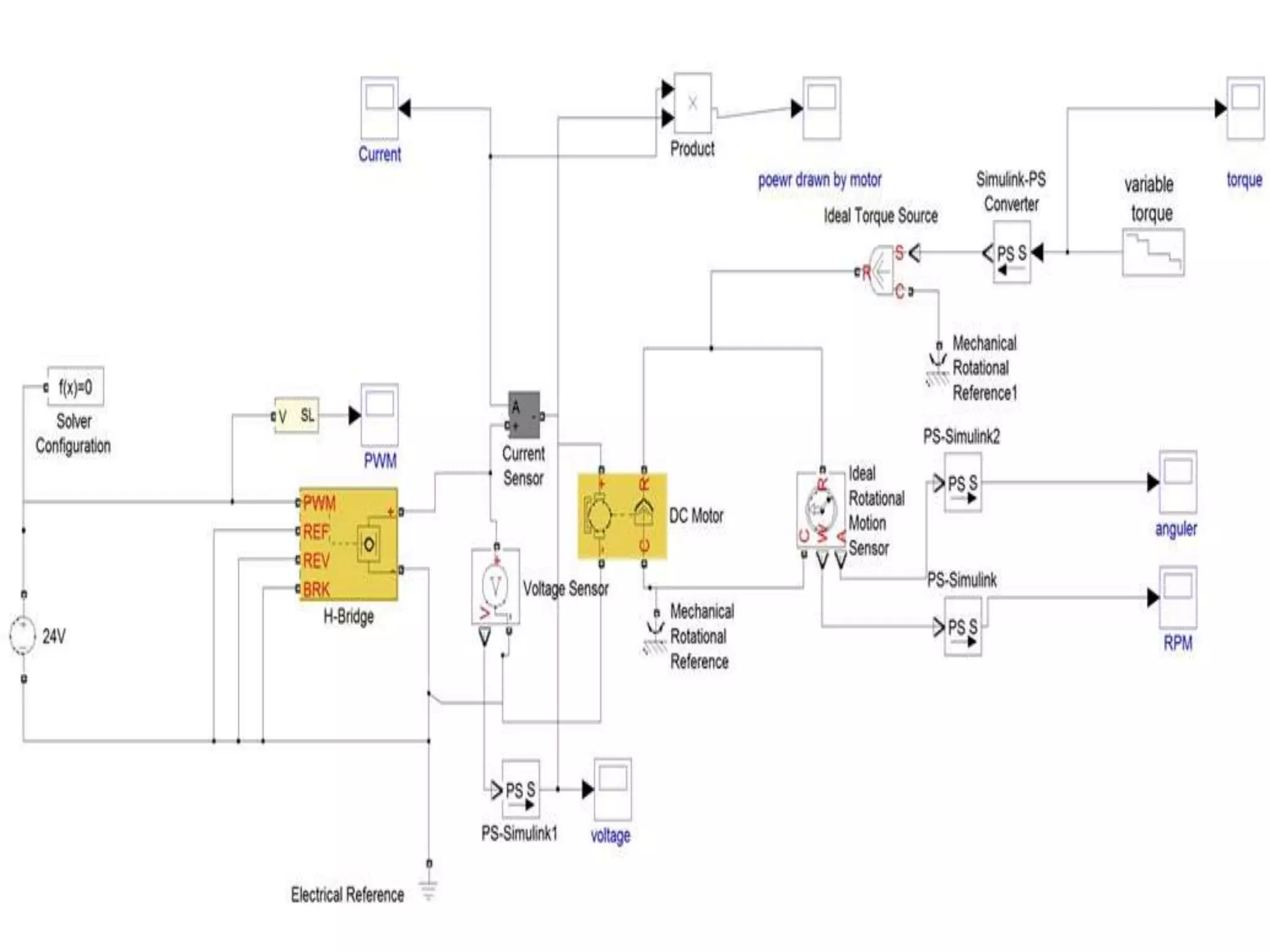
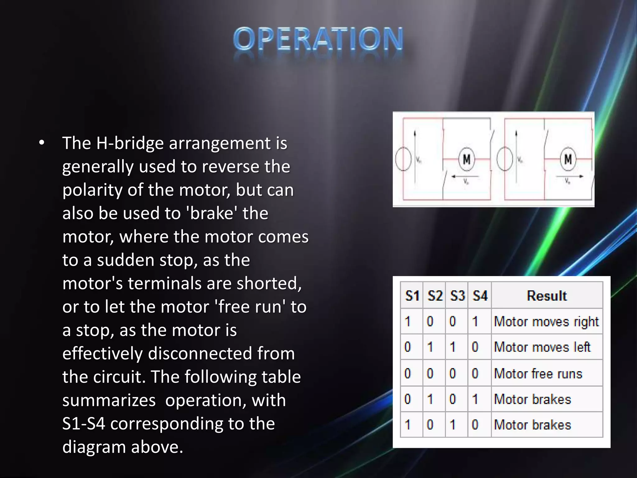
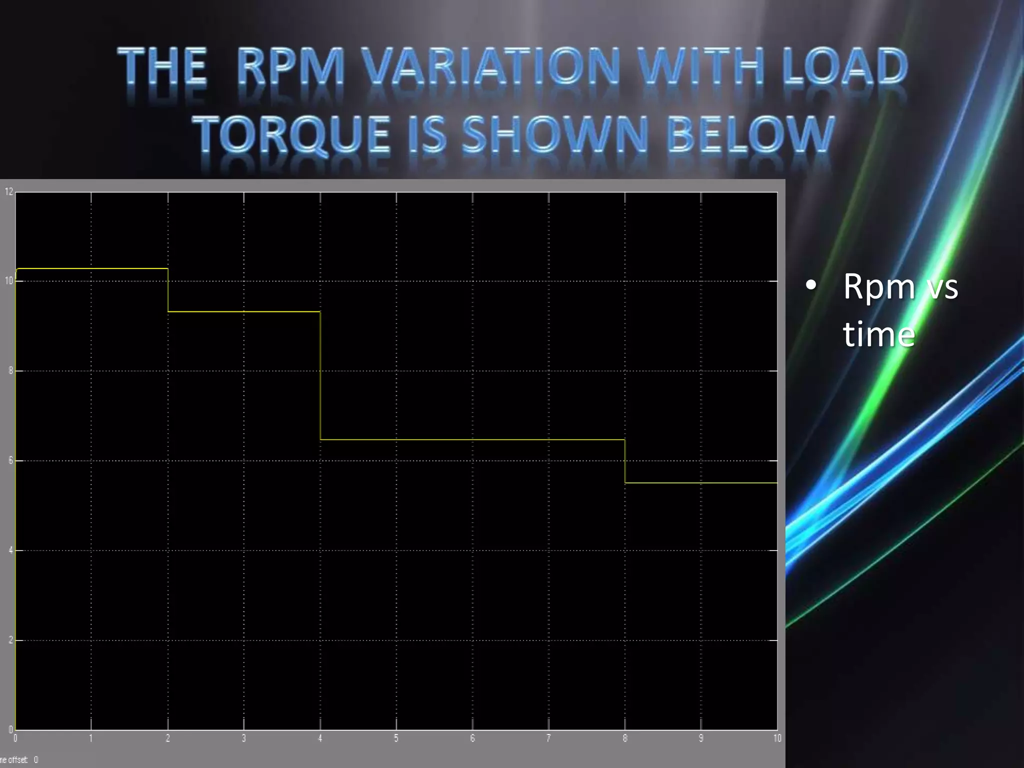
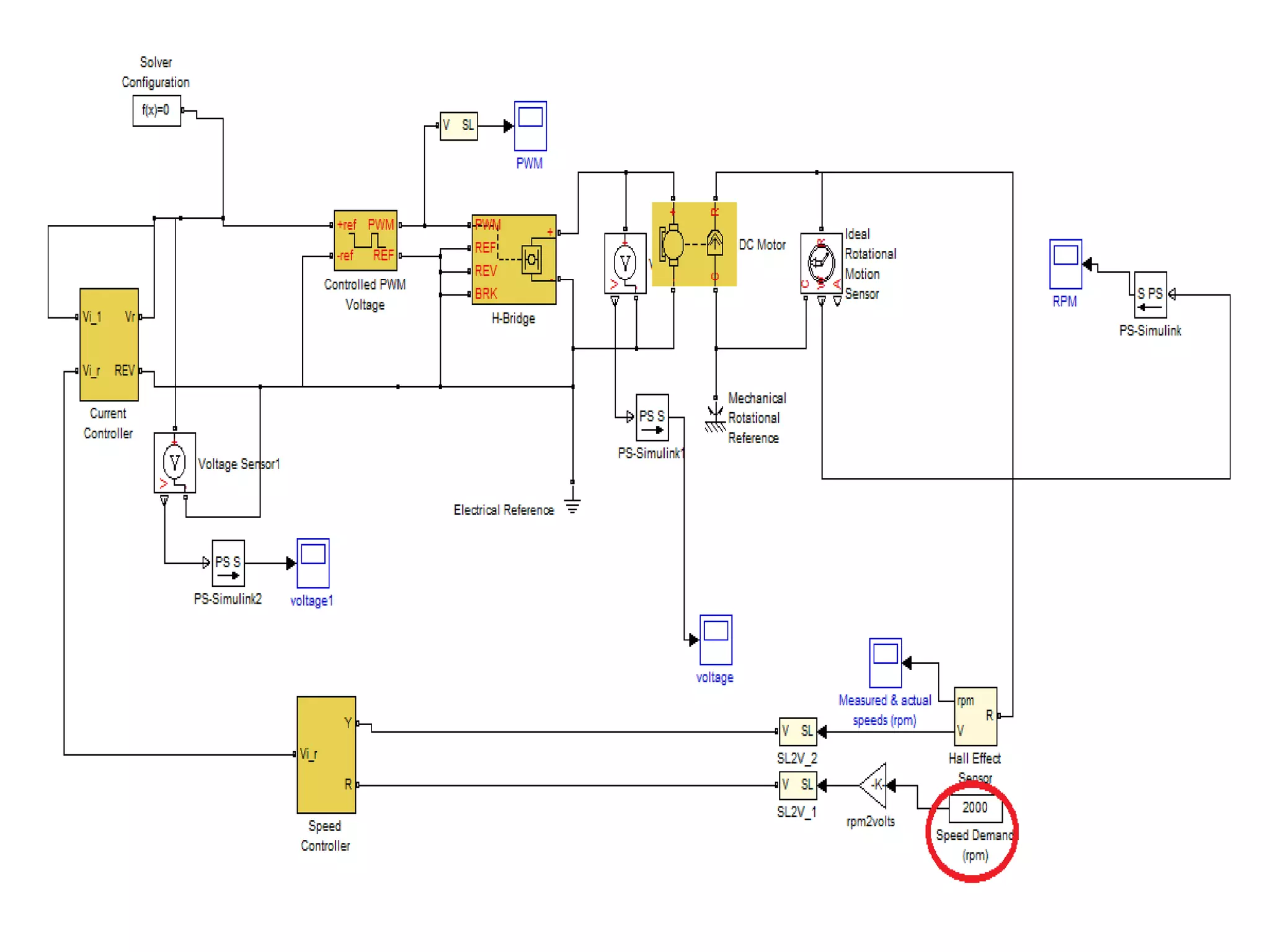
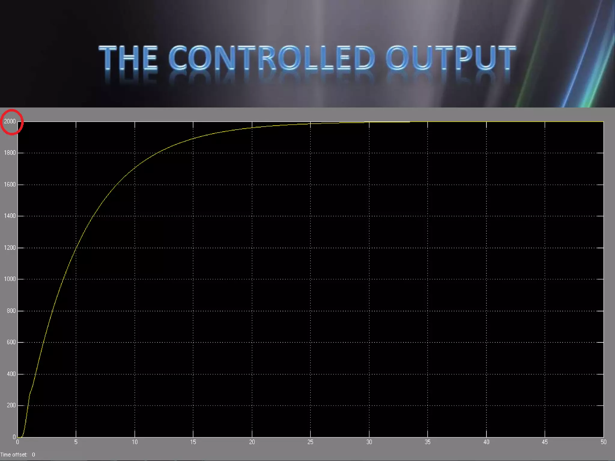
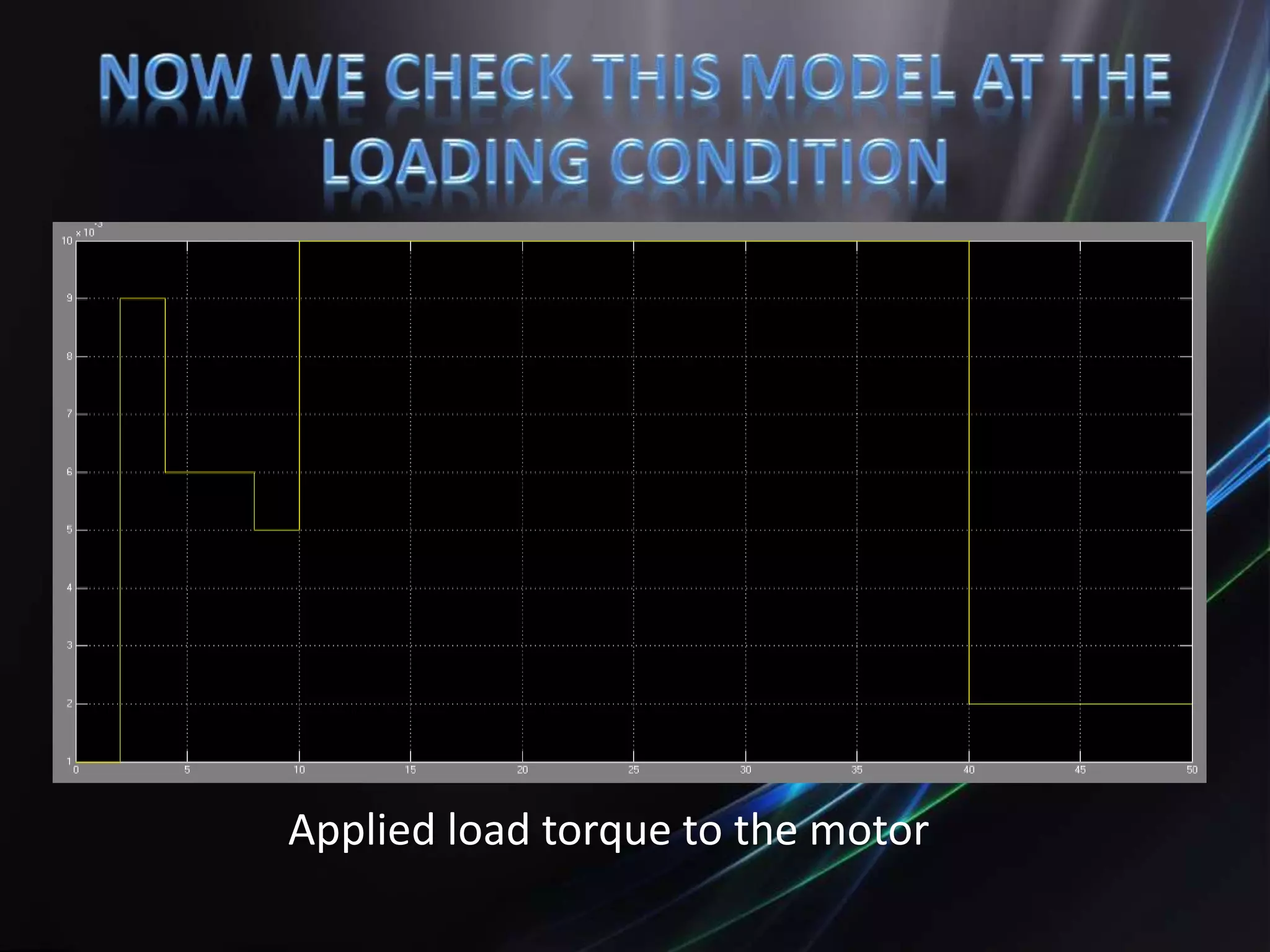
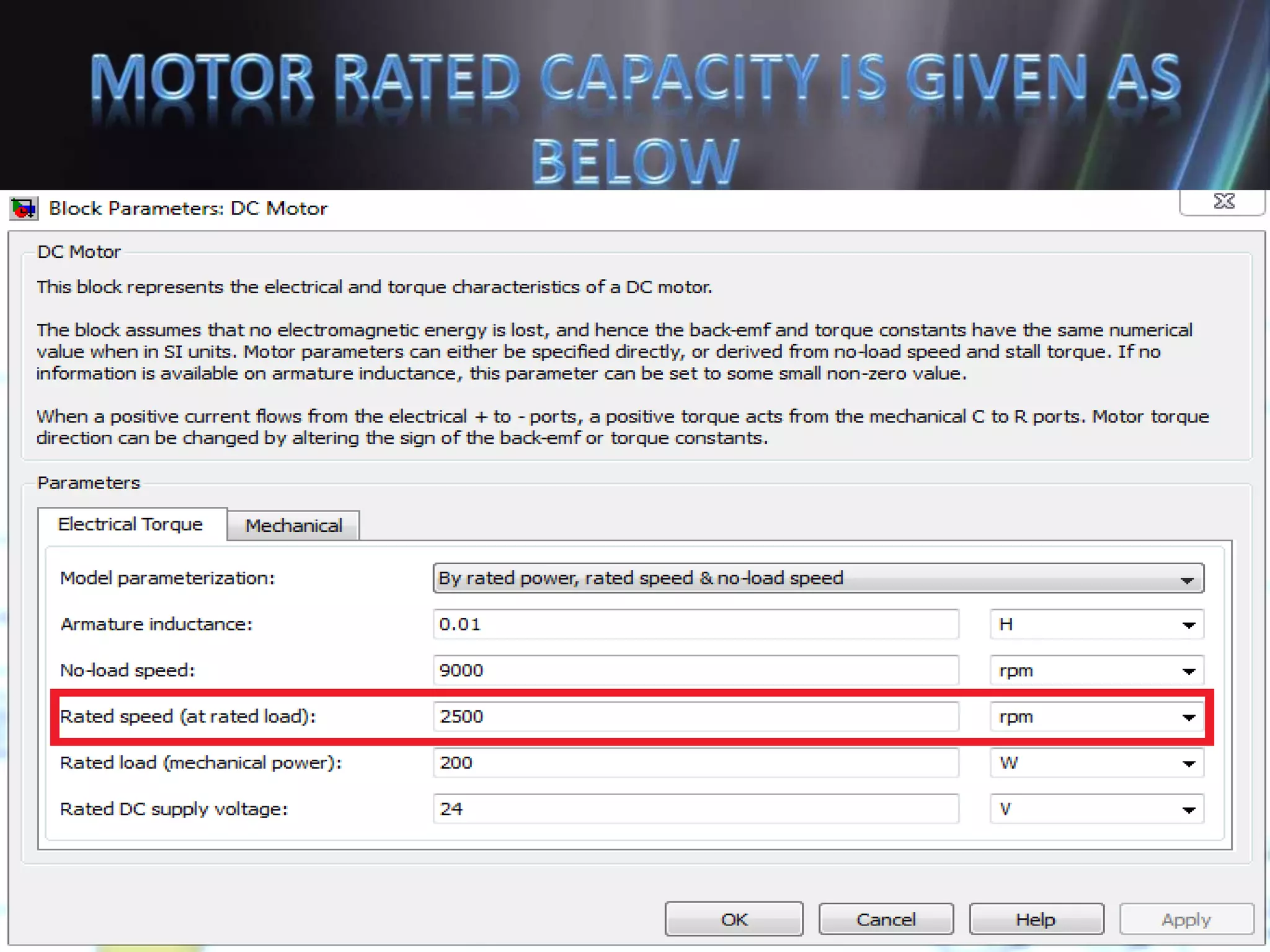
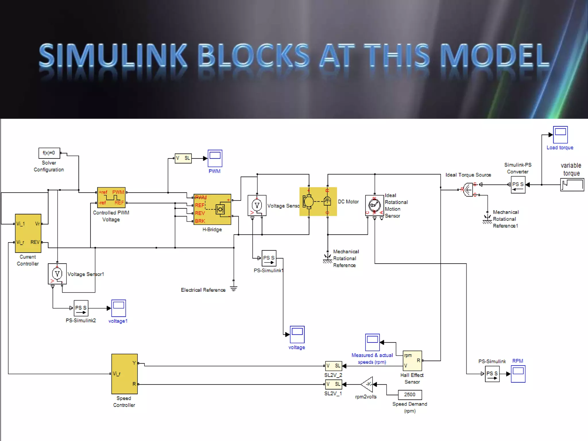
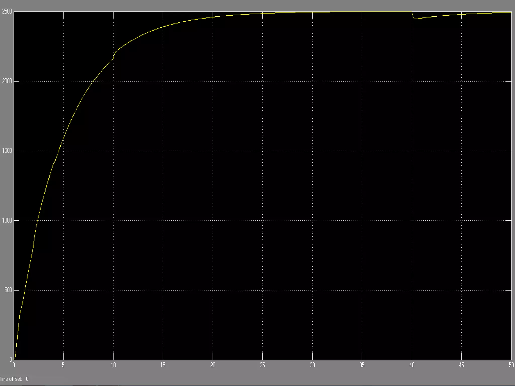
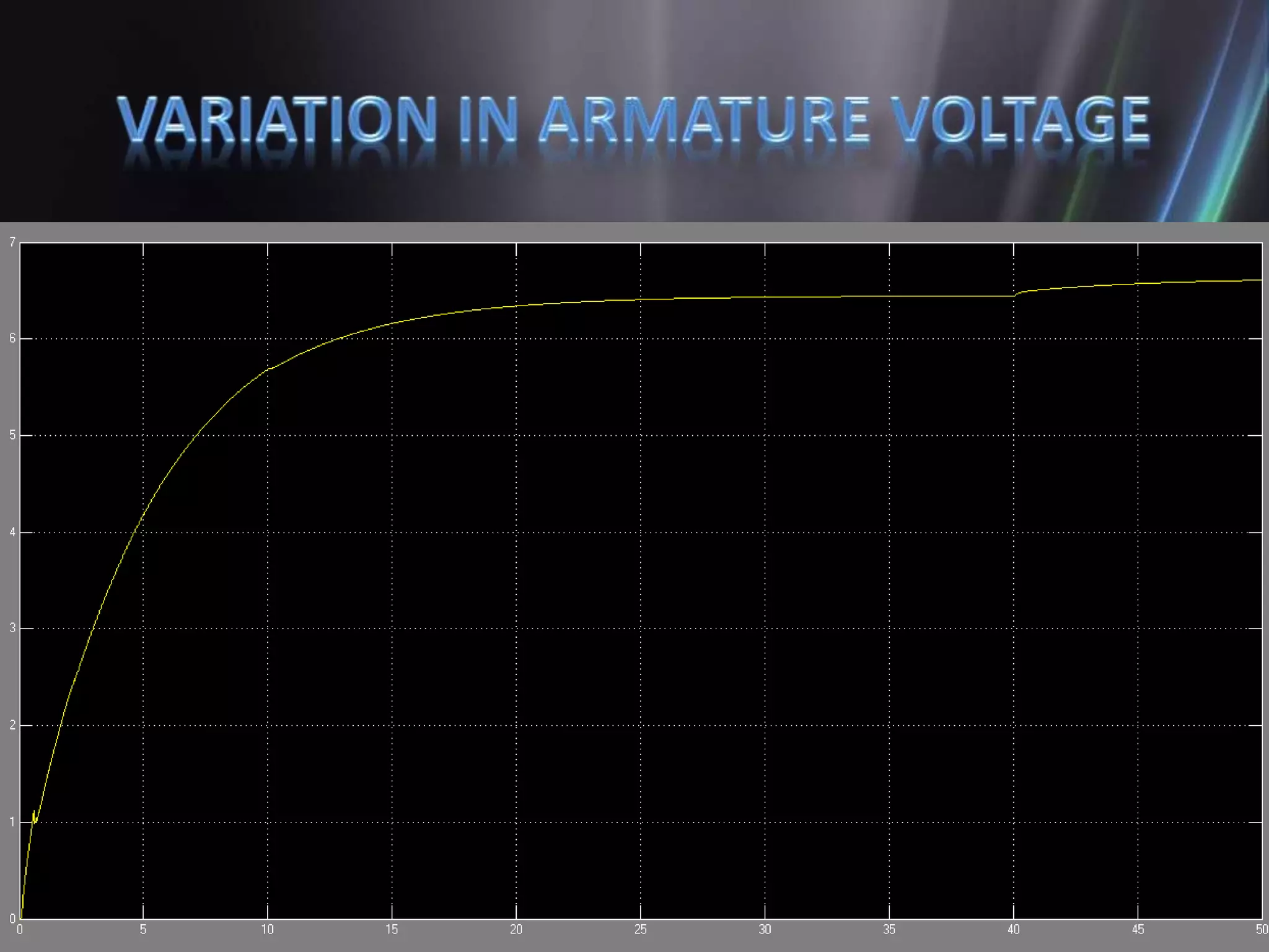
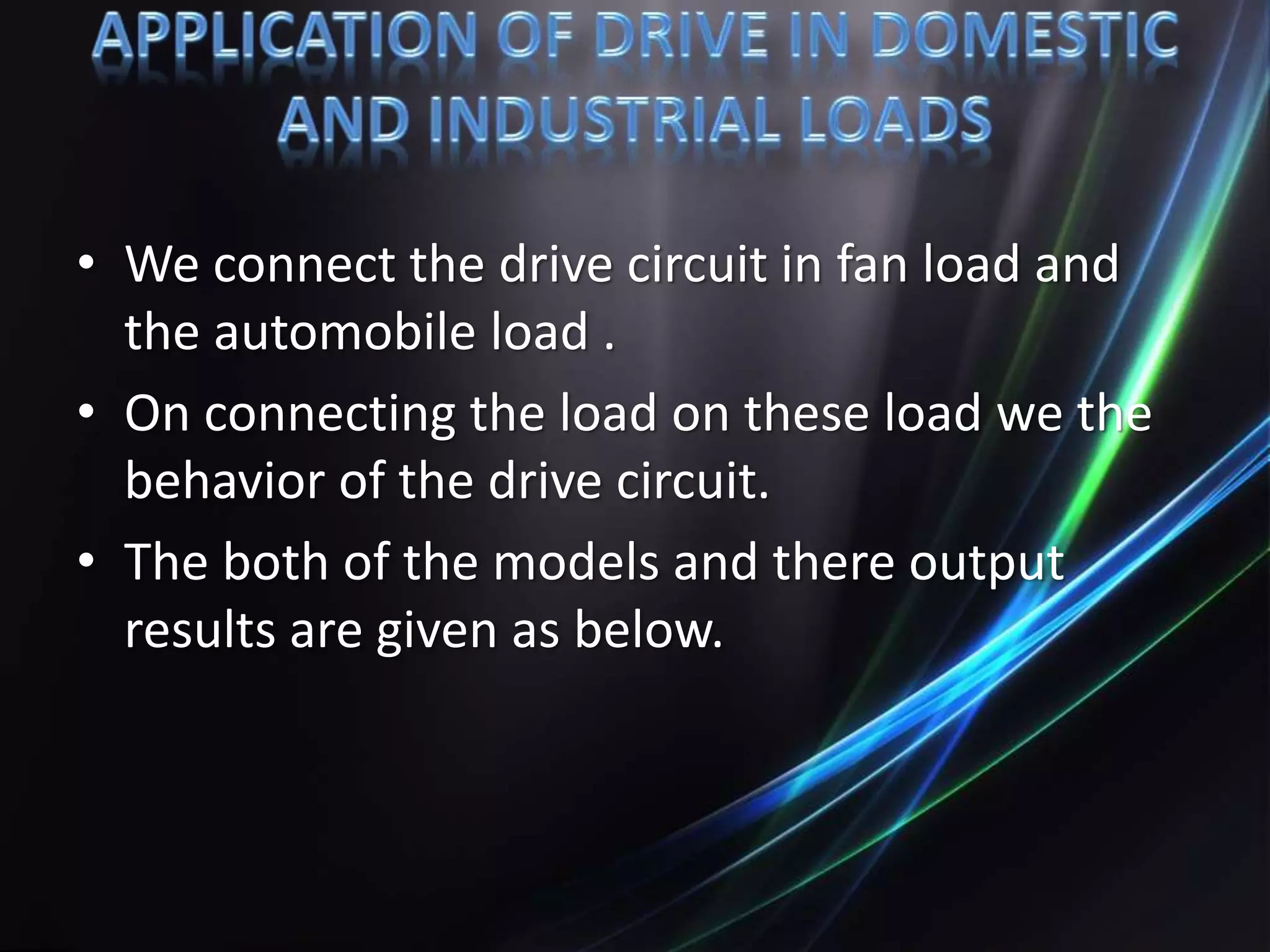
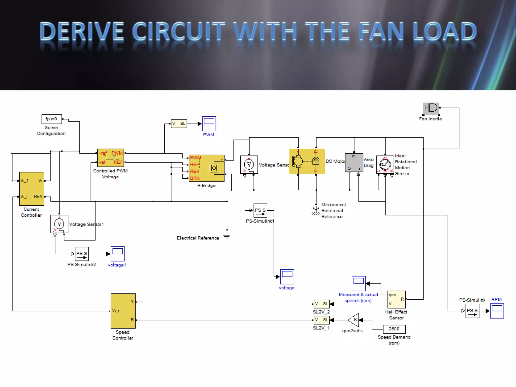
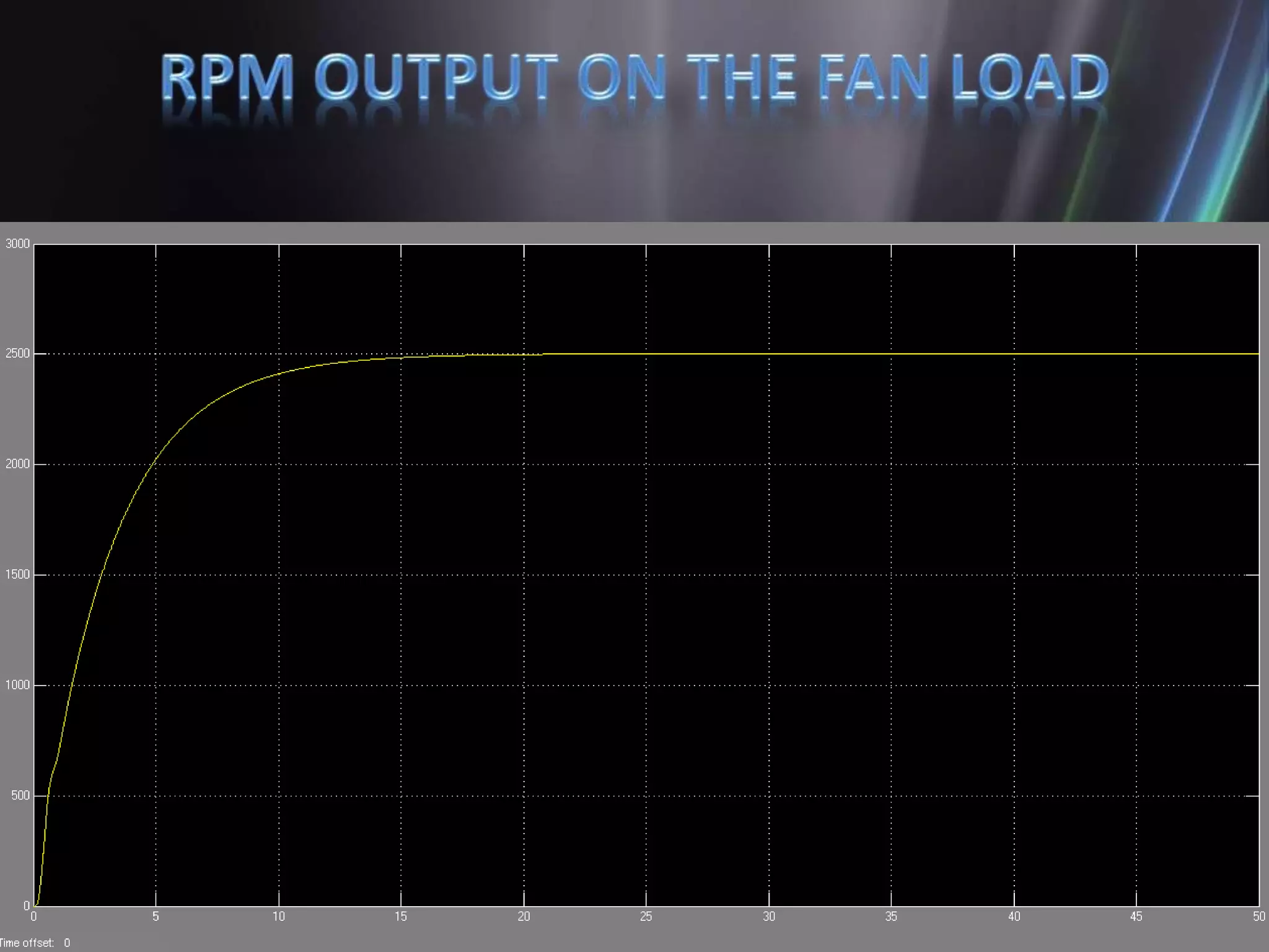
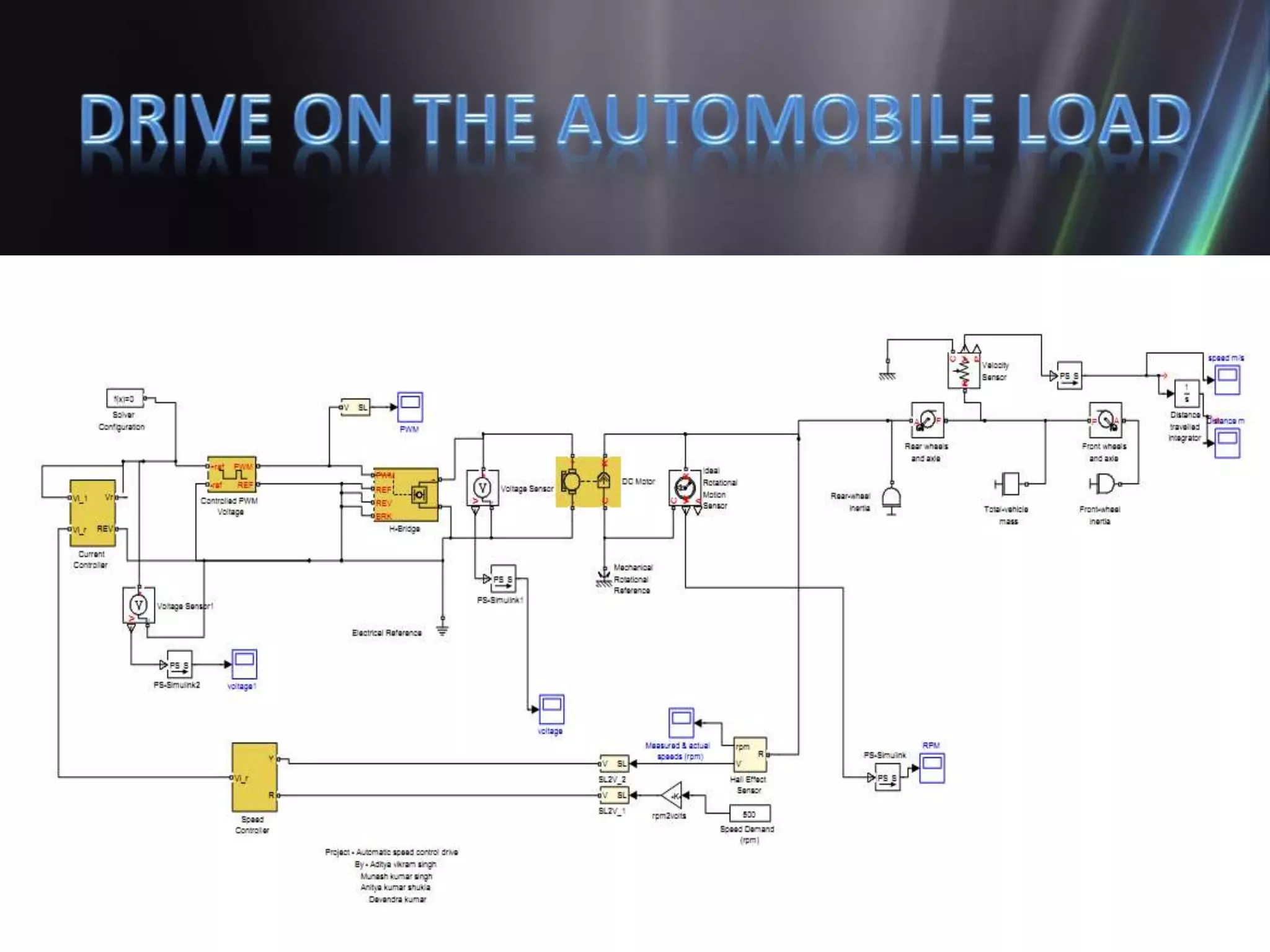
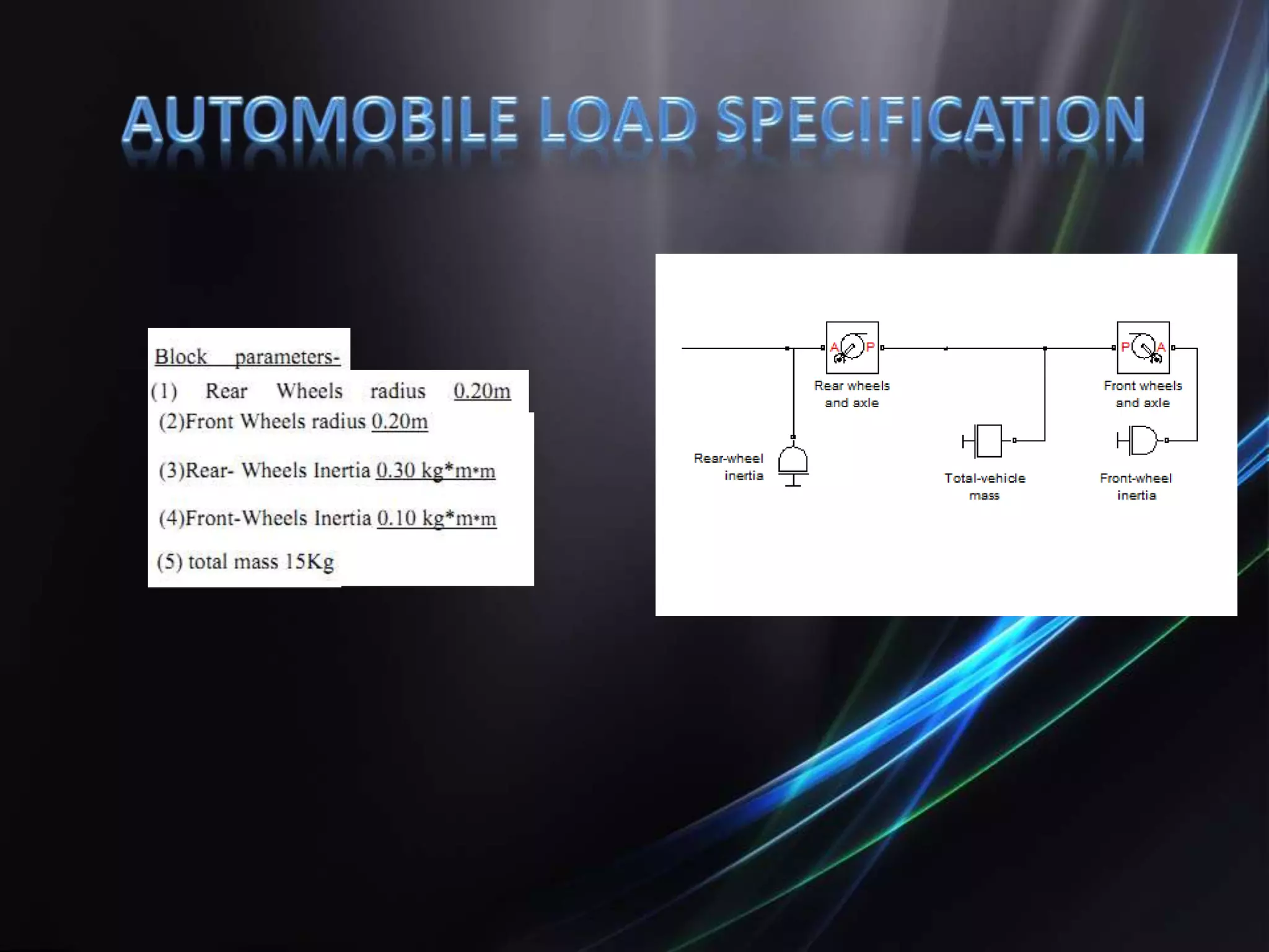
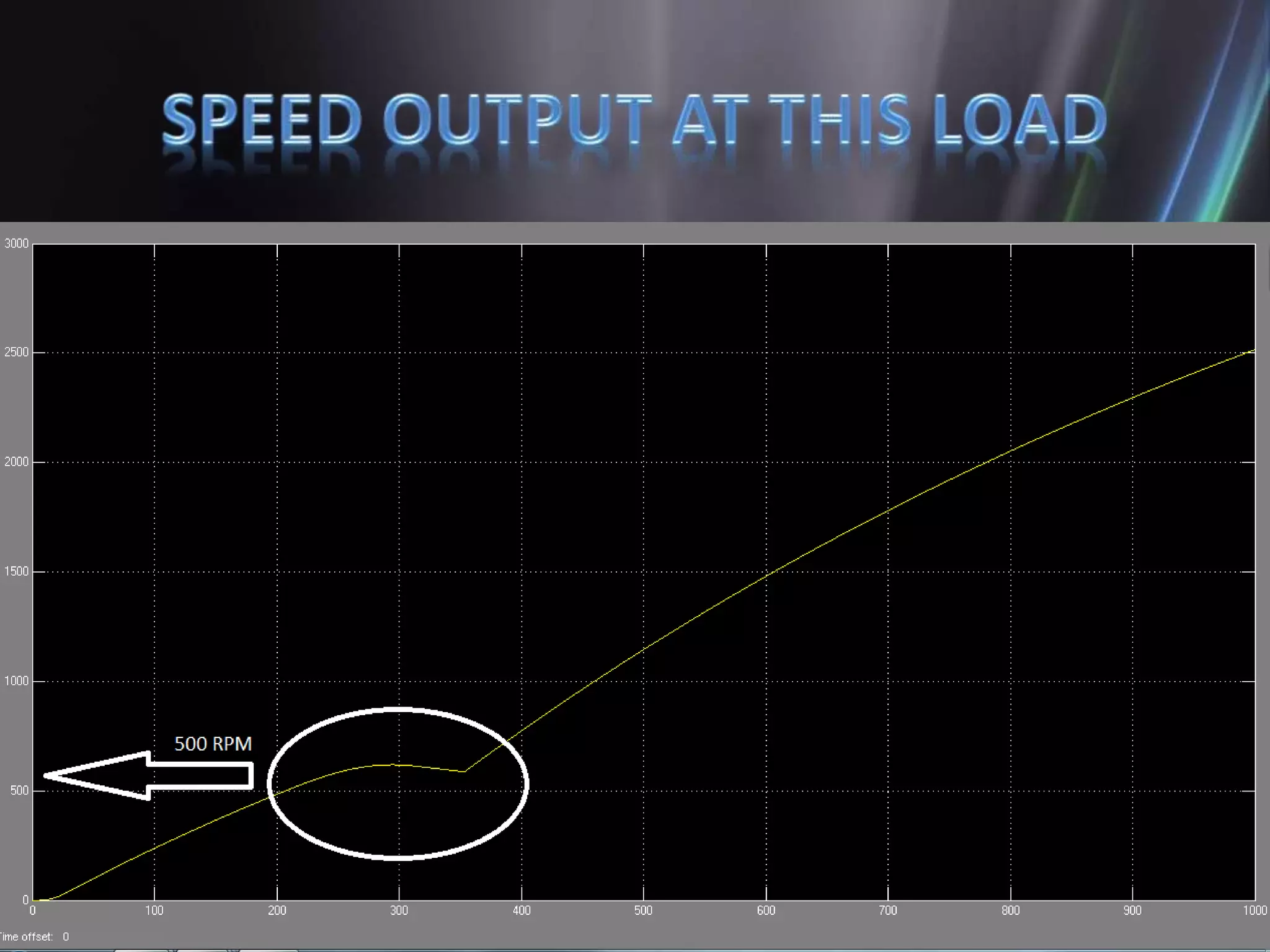
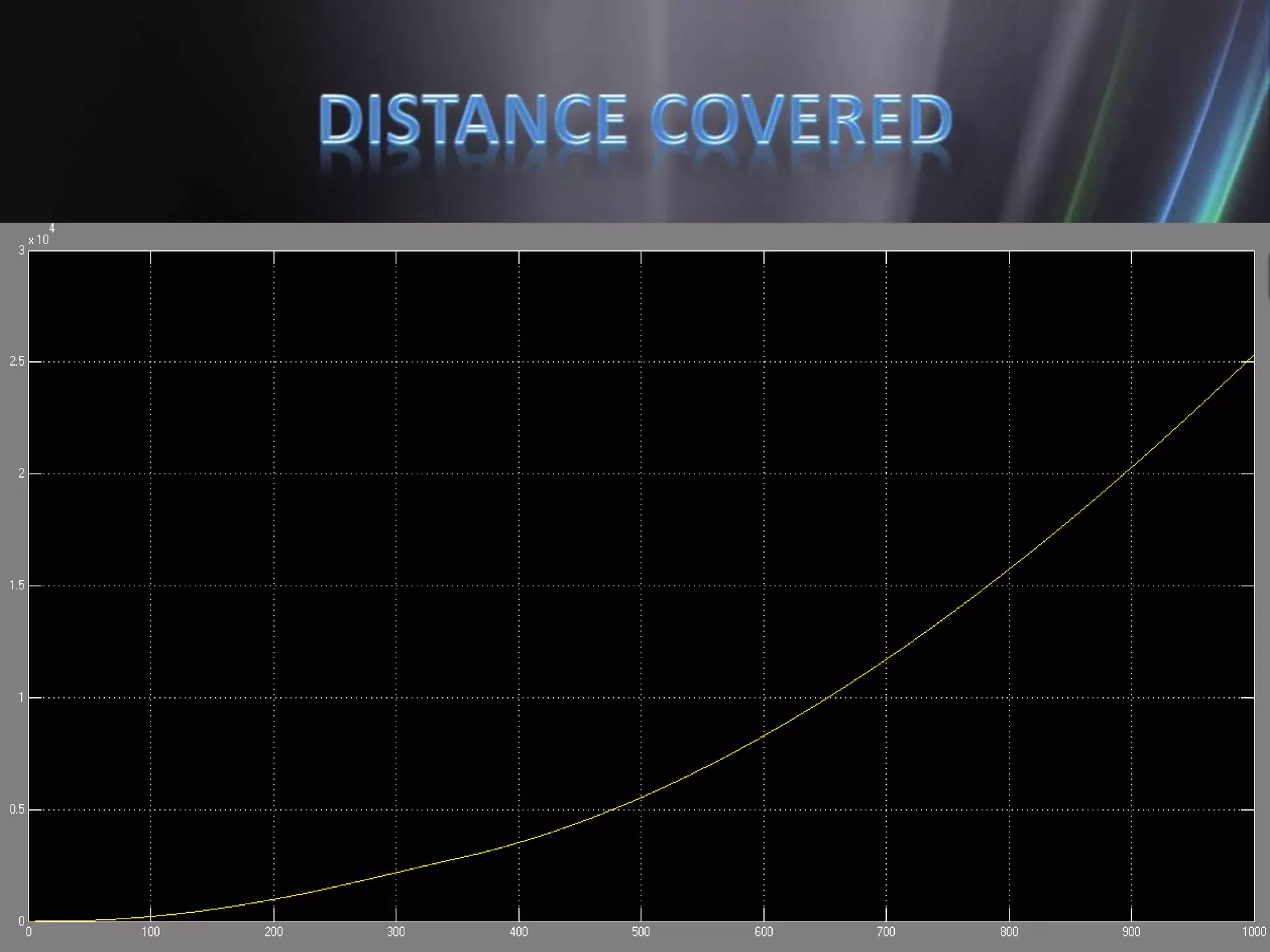
By – Munesh Kumar singh
Aditya Vikram singh
Anitya kumar shukla
Devendra kumar
UNDER THE PROJECT
GUIDANCE OF:-
Mr. Anurag Aggrawal
• Adjustable speed drive (ASD) describes
equipment used to control the speed of
machinery. Many industrial processes such as
assembly lines must operate at different
speeds for different products. Where process
conditions demand adjustment of flow from a
pump or fan, varying the speed of the drive
may save energy compared with other
techniques for flow control.
• Where speeds may be selected from several
different pre-set ranges, usually the drive is
said to be adjustable speed. If the output
speed can be changed without steps over a
range, the drive is usually referred to as
variable speed.
• There are mainly two way to control the speed
of D.C. motors
(1) Direct-current motors allow for changes of
speed by adjusting the shunt field current.
(2) Another way of changing speed of a direct
current motor is to change the voltage
applied to the armature.
• In our project we used to control the armature
Voltage to control the speed of the motor at the
Various given loading conditions .
• The controlling of motor armature voltage is
done with the help of PWM .
• The direction of motor is controlled by H-
bridge.
• There are rotational sensors are placed to
measure the speed(RPM) and angular
displacement of the motor.
• The Simulink modal is shown next.
• An H bridge is an electronic circuit that
enables a voltage to be applied across a load
in either direction. These circuits are often
used in robotics and other applications to
allow DC motors to run forwards and
backwards.
• The H-bridge arrangement is
generally used to reverse the
polarity of the motor, but can
also be used to 'brake' the
motor, where the motor comes
to a sudden stop, as the
motor's terminals are shorted,
or to let the motor 'free run' to
a stop, as the motor is
effectively disconnected from
the circuit. The following table
summarizes operation, with
S1-S4 corresponding to the
diagram above.
• In the previous presentation we shown a
Simulink modal of D.C. drive.
• Which has the variation in the speed with
respect to the load as per the Simulink results.
• For improvement in this section we maintain
the constant speed of the motor (D.C.) at the
various loading conditions.
• In the above shown model there are problem with the
feedback network which we are used .
• We compare the output speed(RPM) and the set
speed(which) required to generate the error signal.
• But this error signal does not provided proper
feedback to the supply .
• Rpm vs
time
• The feedback is applied through Hall sensor .
• The output of the Hall effect sensor is compare with
the rated speed and speed controller gives the
equivalent voltage to the current controller which
produce the equivalent voltage as per the requirement
of the load.
• The improved Simulink model is given below.
Applied load torque to the motor
• As we seen that the applied load torque is
different at the various time intervals.
• The speed should be kept constant in these
time intervals.
• The variation of the speed and armature
voltage given by the simulation result shown
next.
• As shown in the above graph the speed on the
motor kept constant to the set value of the
speed(2500 RPM).
• Which is equal to the rated speed of the
motor.
• We connect the drive circuit in fan load and
the automobile load .
• On connecting the load on these load we the
behavior of the drive circuit.
• The both of the models and there output
results are given as below.
• The drive works on the fan load as per the
requirement .
• But on the automobile load the drive try to
limit the rpm as per the demand but after
some time it does not control the motion.
• We given the speed as per the requirement of
the load and this set speed compare the
speed with the output and generate the error
signal to control the motion of the motor as
per the need.
• But it can also be automatically controlled for
example by using a rotational detector such as
a Gray code optical encoder.
Automatic speed control of DC motor

Automatic speed control of DC motor

  • 1.
    By – MuneshKumar singh Aditya Vikram singh Anitya kumar shukla Devendra kumar UNDER THE PROJECT GUIDANCE OF:- Mr. Anurag Aggrawal
  • 2.
    • Adjustable speeddrive (ASD) describes equipment used to control the speed of machinery. Many industrial processes such as assembly lines must operate at different speeds for different products. Where process conditions demand adjustment of flow from a pump or fan, varying the speed of the drive may save energy compared with other techniques for flow control.
  • 3.
    • Where speedsmay be selected from several different pre-set ranges, usually the drive is said to be adjustable speed. If the output speed can be changed without steps over a range, the drive is usually referred to as variable speed.
  • 5.
    • There aremainly two way to control the speed of D.C. motors (1) Direct-current motors allow for changes of speed by adjusting the shunt field current. (2) Another way of changing speed of a direct current motor is to change the voltage applied to the armature.
  • 6.
    • In ourproject we used to control the armature Voltage to control the speed of the motor at the Various given loading conditions .
  • 7.
    • The controllingof motor armature voltage is done with the help of PWM . • The direction of motor is controlled by H- bridge. • There are rotational sensors are placed to measure the speed(RPM) and angular displacement of the motor. • The Simulink modal is shown next.
  • 9.
    • An Hbridge is an electronic circuit that enables a voltage to be applied across a load in either direction. These circuits are often used in robotics and other applications to allow DC motors to run forwards and backwards.
  • 10.
    • The H-bridgearrangement is generally used to reverse the polarity of the motor, but can also be used to 'brake' the motor, where the motor comes to a sudden stop, as the motor's terminals are shorted, or to let the motor 'free run' to a stop, as the motor is effectively disconnected from the circuit. The following table summarizes operation, with S1-S4 corresponding to the diagram above.
  • 11.
    • In theprevious presentation we shown a Simulink modal of D.C. drive. • Which has the variation in the speed with respect to the load as per the Simulink results. • For improvement in this section we maintain the constant speed of the motor (D.C.) at the various loading conditions.
  • 12.
    • In theabove shown model there are problem with the feedback network which we are used . • We compare the output speed(RPM) and the set speed(which) required to generate the error signal. • But this error signal does not provided proper feedback to the supply .
  • 13.
  • 14.
    • The feedbackis applied through Hall sensor . • The output of the Hall effect sensor is compare with the rated speed and speed controller gives the equivalent voltage to the current controller which produce the equivalent voltage as per the requirement of the load. • The improved Simulink model is given below.
  • 17.
    Applied load torqueto the motor
  • 20.
    • As weseen that the applied load torque is different at the various time intervals. • The speed should be kept constant in these time intervals. • The variation of the speed and armature voltage given by the simulation result shown next.
  • 23.
    • As shownin the above graph the speed on the motor kept constant to the set value of the speed(2500 RPM). • Which is equal to the rated speed of the motor.
  • 24.
    • We connectthe drive circuit in fan load and the automobile load . • On connecting the load on these load we the behavior of the drive circuit. • The both of the models and there output results are given as below.
  • 33.
    • The driveworks on the fan load as per the requirement . • But on the automobile load the drive try to limit the rpm as per the demand but after some time it does not control the motion.
  • 34.
    • We giventhe speed as per the requirement of the load and this set speed compare the speed with the output and generate the error signal to control the motion of the motor as per the need. • But it can also be automatically controlled for example by using a rotational detector such as a Gray code optical encoder.