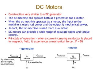
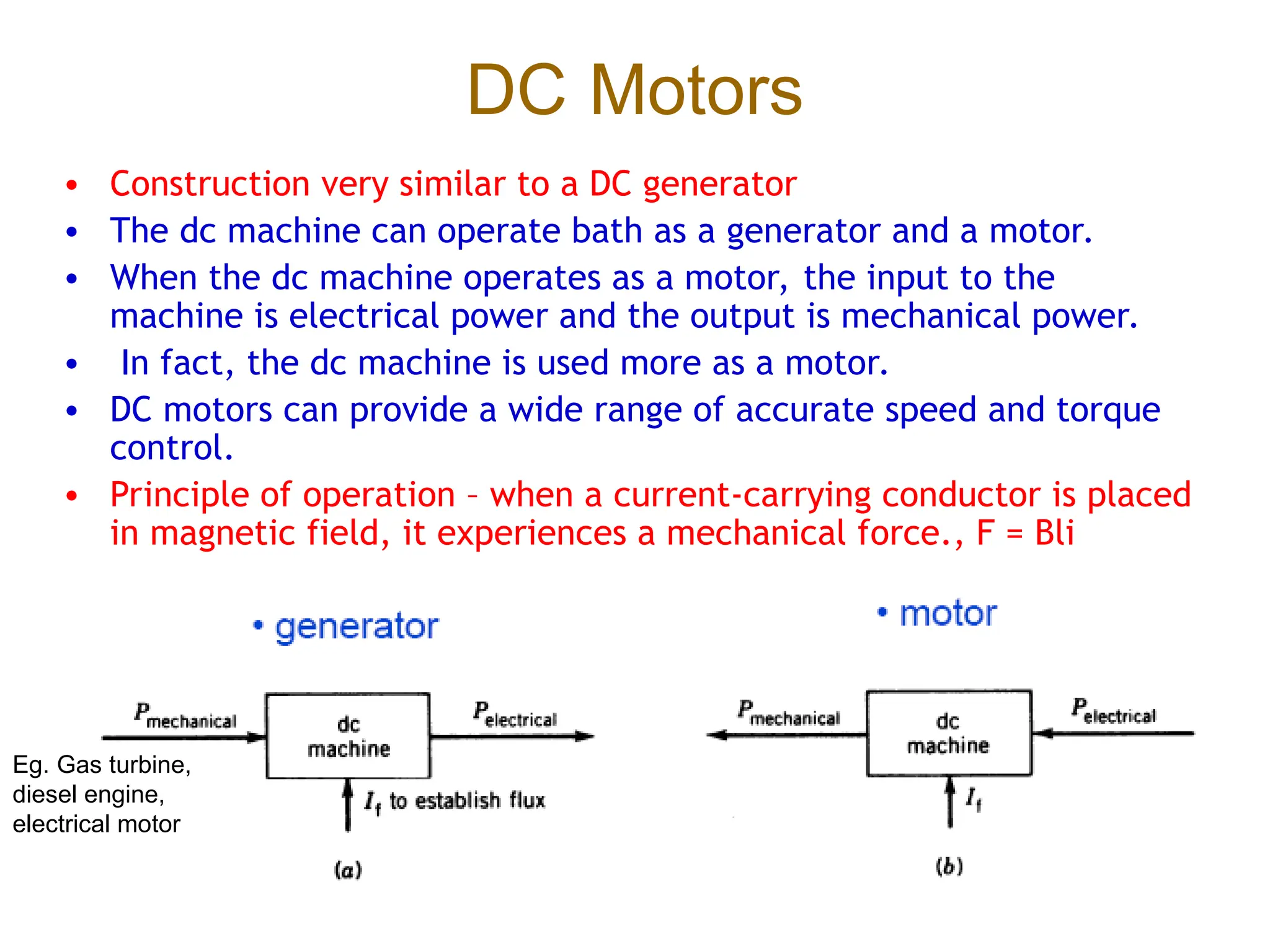
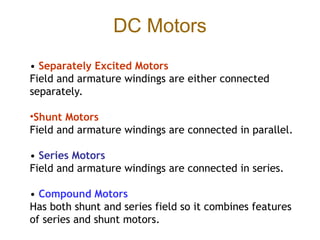
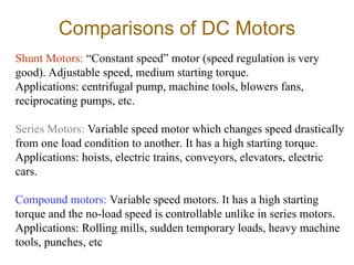
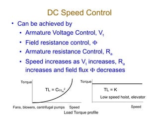
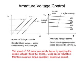
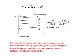
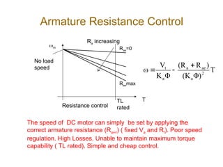
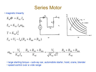
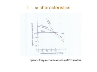
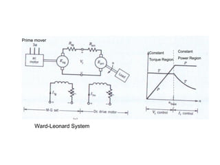
DC Motors
• Construction very similar to a DC generator
• The dc machine can operate bath as a generator and a motor.
• When the dc machine operates as a motor, the input to the
machine is electrical power and the output is mechanical power.
• In fact, the dc machine is used more as a motor.
• DC motors can provide a wide range of accurate speed and torque
control.
• Principle of operation – when a current-carrying conductor is placed
in magnetic field, it experiences a mechanical force., F = Bli
Eg. Gas turbine,
diesel engine,
electrical motor
DC Motors
• Separately Excited Motors
Field and armature windings are either connected
separately.
•Shunt Motors
Field and armature windings are connected in parallel.
• Series Motors
Field and armature windings are connected in series.
• Compound Motors
Has both shunt and series field so it combines features
of series and shunt motors.
Comparisons of DC Motors
Shunt Motors: “Constant speed” motor (speed regulation is very
good). Adjustable speed, medium starting torque.
Applications: centrifugal pump, machine tools, blowers fans,
reciprocating pumps, etc.
Series Motors: Variable speed motor which changes speed drastically
from one load condition to another. It has a high starting torque.
Applications: hoists, electric trains, conveyors, elevators, electric
cars.
Compound motors: Variable speed motors. It has a high starting
torque and the no-load speed is controllable unlike in series motors.
Applications: Rolling mills, sudden temporary loads, heavy machine
tools, punches, etc
Shunt Motor
• The armature circuit and the shunt field circuit are connected across
a dc source of fixed voltage Vt Rfc in the field circuit is used to control
the motor speed by varying if.
= If(Rfc + Rfw)
Power Flow and Efficiency
SHORT SHUNT COMPOUND MOTOR
• depend on machine
size
• Range shown for
machine 1 to 100 kW
Power Flow and Losses in
DC Motors
Pout
Protational
Pinput
VtIt VaIt VaIa EaIa
It
2Rsr It
2Rt Ia
2Ra
– T characteristics
Speed- torque characteristics of DC motors
Example 11
Q. A DC machine (12 kW, 100 V, 1000 rpm) is connected to a 100 V
DC supply and is operated as a DC shunt motor. At no-load
condition, the motor runs at 1000 rpm and the armature current
takes 6 A. Given armature resistance Ra= 0.1 , shunt field
winding resistance Rfw= 80 , and Nf= 1200 turns per pole. The
magnetization characteristic at 1000 rpm is shown in the next
figure.
a. Find the value of shunt field control Rfc
b. Find the rotational losses at 1000 rpm
c. Find the speed, torque, and efficiency when the rated current
flows.
i) Consider the air gap flux remains the same ( no armature reaction) at that at
no load
ii) Consider the air gap flux reduces by 5 % when the rated current flow in the
armature due to the armature reaction
d. Find the starting torque is the starting current is limited to 150 % of
its rated current i) Neglect armature reaction ii) Consider armature
reaction, IfAR = 0.16A
Sen pg. 170
Sol_pg8
Cont. Example
0.99
99.4
Separately Excited DC Motor – Torque
speed characteristic
Vt and flux constant - Drop
in speed as torque increase
is small – good speed
regulation
AR- Improve speed regulation
DC Speed Control
• Can be achieved by
• Armature Voltage Control, Vt
• Field resistance control, 
• Armature resistance Control, Ra
• Speed increases as Vt increases, Ra
increases and field flux  decreases
Torque
Speed
Torque
Speed
TL = Cm
2
Load Torque profile
TL = K
Fans, blowers, centrifugal pumps
Low speed hoist, elevator
T
Vt
m
m
T = 0
T = 1
T = 2
Vt increasing
Vt1
Vt2
Vt3
Vt4
Armature Voltage control-
Constant load torque – speed
varies linearly as Vt changes
Armature Voltage control-
Terminal voltage (Vt) varies-
speed adjusted by varying Vt
Armature Voltage Control
No load
speed
Full load
speed
The speed of DC motor can simply be set by applying the
correct voltage ( fixed flux and Ra). Good speed regulation.
Maintain maximum torque capability. Expensive control.
Field Control
m
Flux decreasing
if1
if2
if3
if4
Rfc max
Rfc=0
T
Field Control
The speed of DC motor can simply be set by applying the
correct field resistance (Rfext) ( fixed Va and Ra). Slow/sluggish
transient respond. Unable to maintain maximum torque
capability. Simple and cheap control.
f
2
a
ae
a
a
t
i
where
T
Φ)
(K
)
R
(R
Φ
K
V
ω





Armature Resistance Control
m
Ra increasing
Raemax
Rae=0
T
Resistance control
The speed of DC motor can simply be set by applying the
correct armature resistance (Raext) ( fixed Va and Rf). Poor speed
regulation. High Losses. Unable to maintain maximum torque
capability ( TL rated). Simple and cheap control.
No load
speed T
Φ)
(K
)
R
(R
Φ
K
V
ω 2
a
ae
a
a
t 


TL
rated
Example 12
• A variable speed drive system uses a dc motor which is
supplied from a variable-voltage source. The drive
speed is varied from 0 to 1500 rpm (base speed) by
varying the terminal voltage from 0 to 500 V with the
field current maintained constant.
(a) Determine the motor armature current if the
torque is held constant at 300 N-m up to the base
speed.
(b) Determine the torque available a speed of 3000
rpm if the armature current is held constant at the
value obtained in part (a).
Neglect all losses.
Sen pg 180
Sol_pg15_motor
Series Motor
T –  characteristics
Speed- torque characteristics of DC motors
Example 13
• A 220 V, 7 hp series motor is mechanically coupled to a
fan and draws 25 amps and runs at 300 rpm when
connected to a 220 V supply with no external resistance
connected to the armature circuit (Rae= 0 ). The
torque required by the fan is proportional to the square
of the speed. Ra= 0.6  and Rsr= 0.4 . Neglect
armature reaction and rotational loss.
(a) Determine the power delivered to the fan and the
torque developed by the machine.
(b) The speed is to be reduced to 200 rpm by inserting
a resistance Rae in the armature circuit. Determine the
value of this resistance and the power delivered to the
fan.
PC Sen pg 182
Sol_pg18
Motor Starter
• If a DC motor directly connected to a DC supply, the
starting current will be dangerously high
a
t
a
a
a
t
a
R
V
I
start;
at
0
R
E
V
I







a
a K
E
•Ra small, Ia large. Ia can be limited to a safe value by:
•Insert an external resistance, Rae
•Use a low dc voltage (Vt) at starts, which require a
variable-voltage supply
•With external resistance,
ae
a
a
t
a
R
R
E
V
I



Motor Starter
Development of a DC motor starter
Ea  speed (). As
speed increases Rae
can be gradually
taken out without the
current exceed a
limit ( starter box).
Initially at position 1,
as the speed
increases, the
starter move to
position 2,3,4and 5,
Example 13.1
A 10 kW , 100 V , 1000 rpm dc machine has Ra=0.1
ohm and is connected to a 100 V dc supply.
a)Determine the starting current if no starting
resistance is used in the armature circuit
b)Determine the value of the starting resistance if
the starting current is limited to twice the rated
current
c)This dc machine is to run as a motor, using starter
box. Determine the values of resistance required in
the starter box such that the armature current Ia is
constraint within 100% to 200% of its rated value
during start-up.
Sol_pg21
Permanent Magnet DC motor
• Widely used in low power application
• Field winding is replaced by a permanent
magnet (simple construction and less space)
• No requirement on external excitation
• Limitation imposed by the permanent magnet
themselves such as demagnetization and
overheating)
Equation Ea = Kadm becomes Ea = Kmm
Example 14
• A permanent magnet DC motor has Ra = 1.03  .
When operated at no-load from a DC source of 50
V, its operates at 2100 rpm and draw a current of
1.25 A. Find:
i. The torque constant, Km
ii. The no-load rotational losses
iii. The armature current and the motor power
output when it is operating at 1700 rpm from a 48 V
source
Fgrt; pg 389: 0.22 V/(rad/sec), 61 W, 8.54A, 274 W
Sol_pg23
Speed Control
• Numerous applications require control of speed, as in
rolling mills, cranes, hoists, elevators, machine tools,
and locomotive drives.
• DC motors are extensively used in many of these
applications.
• Control of dc motors speed below and above the base
(rated) speed can easily be achieved.
• The methods of control are simpler and less expensive
than ac motors.
• Classis way used Ward-Leonard System, latest used
solid-state converters.
Ward-Leonard System
• In the classical method, a Ward-Leonard system(1890s) with
rotating machines is used for speed control of dc motors. The
system uses the motor-generator set ( M-G set) control the
speed of a DC motor. Normally AC motor runs at constant speed
is used as prime mover.
The system is operated in two control methods:
• Vt Control; In the armature voltage control mode, the motor
current Ifm is kept constant at its rated value. The generator
field current Ifg is changed such that Vt changes from zero to its
rated.
• If Control; The field current control mode is used to obtain
speed above the base speed. In this mode, the armature voltage
Vt remains constant and the motor field current Ifm is decreased
to obtain higher speeds .
Constant
Torque Region
Constant
Power Region
Ward-Leonard System
Prime mover
Solid-State Control
• In recent years, solid state converters have been used
(replace motor- generator set) to control the speed of
dc motors.
The converter used are controlled rectifiers or choppers:
Controlled Rectifiers
• If the supply is ac, controlled rectifiers can be used to
convert a fixed ac supply voltage into variable-voltage
dc supply (using SCR). High ripple, slow response
Choppers
• A solid state chopper converts a fixed-voltage dc supply
into a variable-voltage dc supply(Using controllable
swithes such as Power Mosfet, Power BJT, IGBT, GTO
etc).Low ripple, fast response
Single phase rectifier
Controlled Rectifier


cos
3 l
l
V
V m
t


Three phase rectifier


cos
2 m
t
V
V 
1-phase or 3-phase
Eg: Va and Vf Control using solid state
devices – single phase supply
+
vs
_
Ia
Ta1
Ta2
Ta3
+
+

Va
Ra
Ta4
La
E
g

If
+
vs
_
Tf1
Tf2
Tf3
+

Lf
Tf4
Lf
Vf
ARMATURE FIELD
Chopper Control
in
on
in
t V
T
T
DV
V 

Closed-loop Operation
• Open loop operation: If load torque changes,
the speed will change too – not satisfactory.
• May not be satisfactory in many applications
where a constant speed is required
• Close loop operation: the speed can be
maintained constant by adjusting the motor
terminal voltage as the load torque changes.
(eg. Load torque increases, speed decreases, speed
error eN increases, results in control signal Vc increases
– decrease in the converter firing angle (controlled
rectifeir), or increases in duty cycle (chopper) to
restore back the speed)
Closed loop speed control system (basic system)
Chopper or Control
rectifier
Speed
demand
Voltage
control
Speed
demand
Current/torque
demand
Closed-loop speed control with inner current loop
Example 15
• The speed of a 10 hp, 220 V, 1200 rpm
separately excited DC motor is controlled by a
single-phase full-controlled converter. The rated
current is 40 A. Ra= 0.25 ohm, and La= 10mH.
The AC supply voltage is 265 V. Motor constant is
Ka=0.18 V/rpm. Assume the motor current is
constant and ripple free. For firing angle  = 30
degree, determine:
(a) Speed of the motor
(b) Motor Torque
(c) Power to the motor.
Sen pg 191
Sol_pg34
Example: 2009/10
Question 3
(a) Describe briefly classification of self-excited DC motor based on connections of field
circuit and armature circuit. Sketch the torque speed profile for this type of motor.
(b) A 500 V shunt motor takes a current of 21 A and runs at 400 rpm on full load. The
armature resistance and field resistance are 0.3  and 500  respectively. In order to
control the speed, an additional resistance is added in series in the armature circuit.
The flux remains constant in the machine.
(i) Sketch the new schematic diagram with armature resistance motor speed control.
(ii) Find the motor speed at full load when an additional resistance of 2  is added in
armature circuit.
(iii) Find the motor speed at double full-load with added resistance of Qb(ii).
(iv) Find the motor starting current with an additional resistance of 2 .
(v) Find the required value of the additional armature resistance to reduce the speed to half
of its rated speed at full load.
Sol_pg32

DC Motors and Generators Construction and Working.ppt

  • 1.
    DC Motors • Constructionvery similar to a DC generator • The dc machine can operate bath as a generator and a motor. • When the dc machine operates as a motor, the input to the machine is electrical power and the output is mechanical power. • In fact, the dc machine is used more as a motor. • DC motors can provide a wide range of accurate speed and torque control. • Principle of operation – when a current-carrying conductor is placed in magnetic field, it experiences a mechanical force., F = Bli Eg. Gas turbine, diesel engine, electrical motor
  • 2.
    DC Motors • SeparatelyExcited Motors Field and armature windings are either connected separately. •Shunt Motors Field and armature windings are connected in parallel. • Series Motors Field and armature windings are connected in series. • Compound Motors Has both shunt and series field so it combines features of series and shunt motors.
  • 3.
    Comparisons of DCMotors Shunt Motors: “Constant speed” motor (speed regulation is very good). Adjustable speed, medium starting torque. Applications: centrifugal pump, machine tools, blowers fans, reciprocating pumps, etc. Series Motors: Variable speed motor which changes speed drastically from one load condition to another. It has a high starting torque. Applications: hoists, electric trains, conveyors, elevators, electric cars. Compound motors: Variable speed motors. It has a high starting torque and the no-load speed is controllable unlike in series motors. Applications: Rolling mills, sudden temporary loads, heavy machine tools, punches, etc
  • 4.
    Shunt Motor • Thearmature circuit and the shunt field circuit are connected across a dc source of fixed voltage Vt Rfc in the field circuit is used to control the motor speed by varying if. = If(Rfc + Rfw)
  • 5.
    Power Flow andEfficiency SHORT SHUNT COMPOUND MOTOR • depend on machine size • Range shown for machine 1 to 100 kW
  • 6.
    Power Flow andLosses in DC Motors Pout Protational Pinput VtIt VaIt VaIa EaIa It 2Rsr It 2Rt Ia 2Ra
  • 7.
    – T characteristics Speed-torque characteristics of DC motors
  • 8.
    Example 11 Q. ADC machine (12 kW, 100 V, 1000 rpm) is connected to a 100 V DC supply and is operated as a DC shunt motor. At no-load condition, the motor runs at 1000 rpm and the armature current takes 6 A. Given armature resistance Ra= 0.1 , shunt field winding resistance Rfw= 80 , and Nf= 1200 turns per pole. The magnetization characteristic at 1000 rpm is shown in the next figure. a. Find the value of shunt field control Rfc b. Find the rotational losses at 1000 rpm c. Find the speed, torque, and efficiency when the rated current flows. i) Consider the air gap flux remains the same ( no armature reaction) at that at no load ii) Consider the air gap flux reduces by 5 % when the rated current flow in the armature due to the armature reaction d. Find the starting torque is the starting current is limited to 150 % of its rated current i) Neglect armature reaction ii) Consider armature reaction, IfAR = 0.16A Sen pg. 170 Sol_pg8
  • 9.
  • 10.
    Separately Excited DCMotor – Torque speed characteristic Vt and flux constant - Drop in speed as torque increase is small – good speed regulation AR- Improve speed regulation
  • 11.
    DC Speed Control •Can be achieved by • Armature Voltage Control, Vt • Field resistance control,  • Armature resistance Control, Ra • Speed increases as Vt increases, Ra increases and field flux  decreases Torque Speed Torque Speed TL = Cm 2 Load Torque profile TL = K Fans, blowers, centrifugal pumps Low speed hoist, elevator
  • 12.
    T Vt m m T = 0 T= 1 T = 2 Vt increasing Vt1 Vt2 Vt3 Vt4 Armature Voltage control- Constant load torque – speed varies linearly as Vt changes Armature Voltage control- Terminal voltage (Vt) varies- speed adjusted by varying Vt Armature Voltage Control No load speed Full load speed The speed of DC motor can simply be set by applying the correct voltage ( fixed flux and Ra). Good speed regulation. Maintain maximum torque capability. Expensive control.
  • 13.
    Field Control m Flux decreasing if1 if2 if3 if4 Rfcmax Rfc=0 T Field Control The speed of DC motor can simply be set by applying the correct field resistance (Rfext) ( fixed Va and Ra). Slow/sluggish transient respond. Unable to maintain maximum torque capability. Simple and cheap control. f 2 a ae a a t i where T Φ) (K ) R (R Φ K V ω     
  • 14.
    Armature Resistance Control m Raincreasing Raemax Rae=0 T Resistance control The speed of DC motor can simply be set by applying the correct armature resistance (Raext) ( fixed Va and Rf). Poor speed regulation. High Losses. Unable to maintain maximum torque capability ( TL rated). Simple and cheap control. No load speed T Φ) (K ) R (R Φ K V ω 2 a ae a a t    TL rated
  • 15.
    Example 12 • Avariable speed drive system uses a dc motor which is supplied from a variable-voltage source. The drive speed is varied from 0 to 1500 rpm (base speed) by varying the terminal voltage from 0 to 500 V with the field current maintained constant. (a) Determine the motor armature current if the torque is held constant at 300 N-m up to the base speed. (b) Determine the torque available a speed of 3000 rpm if the armature current is held constant at the value obtained in part (a). Neglect all losses. Sen pg 180 Sol_pg15_motor
  • 16.
  • 17.
    T – characteristics Speed- torque characteristics of DC motors
  • 18.
    Example 13 • A220 V, 7 hp series motor is mechanically coupled to a fan and draws 25 amps and runs at 300 rpm when connected to a 220 V supply with no external resistance connected to the armature circuit (Rae= 0 ). The torque required by the fan is proportional to the square of the speed. Ra= 0.6  and Rsr= 0.4 . Neglect armature reaction and rotational loss. (a) Determine the power delivered to the fan and the torque developed by the machine. (b) The speed is to be reduced to 200 rpm by inserting a resistance Rae in the armature circuit. Determine the value of this resistance and the power delivered to the fan. PC Sen pg 182 Sol_pg18
  • 19.
    Motor Starter • Ifa DC motor directly connected to a DC supply, the starting current will be dangerously high a t a a a t a R V I start; at 0 R E V I        a a K E •Ra small, Ia large. Ia can be limited to a safe value by: •Insert an external resistance, Rae •Use a low dc voltage (Vt) at starts, which require a variable-voltage supply •With external resistance, ae a a t a R R E V I   
  • 20.
    Motor Starter Development ofa DC motor starter Ea  speed (). As speed increases Rae can be gradually taken out without the current exceed a limit ( starter box). Initially at position 1, as the speed increases, the starter move to position 2,3,4and 5,
  • 21.
    Example 13.1 A 10kW , 100 V , 1000 rpm dc machine has Ra=0.1 ohm and is connected to a 100 V dc supply. a)Determine the starting current if no starting resistance is used in the armature circuit b)Determine the value of the starting resistance if the starting current is limited to twice the rated current c)This dc machine is to run as a motor, using starter box. Determine the values of resistance required in the starter box such that the armature current Ia is constraint within 100% to 200% of its rated value during start-up. Sol_pg21
  • 22.
    Permanent Magnet DCmotor • Widely used in low power application • Field winding is replaced by a permanent magnet (simple construction and less space) • No requirement on external excitation • Limitation imposed by the permanent magnet themselves such as demagnetization and overheating) Equation Ea = Kadm becomes Ea = Kmm
  • 23.
    Example 14 • Apermanent magnet DC motor has Ra = 1.03  . When operated at no-load from a DC source of 50 V, its operates at 2100 rpm and draw a current of 1.25 A. Find: i. The torque constant, Km ii. The no-load rotational losses iii. The armature current and the motor power output when it is operating at 1700 rpm from a 48 V source Fgrt; pg 389: 0.22 V/(rad/sec), 61 W, 8.54A, 274 W Sol_pg23
  • 24.
    Speed Control • Numerousapplications require control of speed, as in rolling mills, cranes, hoists, elevators, machine tools, and locomotive drives. • DC motors are extensively used in many of these applications. • Control of dc motors speed below and above the base (rated) speed can easily be achieved. • The methods of control are simpler and less expensive than ac motors. • Classis way used Ward-Leonard System, latest used solid-state converters.
  • 25.
    Ward-Leonard System • Inthe classical method, a Ward-Leonard system(1890s) with rotating machines is used for speed control of dc motors. The system uses the motor-generator set ( M-G set) control the speed of a DC motor. Normally AC motor runs at constant speed is used as prime mover. The system is operated in two control methods: • Vt Control; In the armature voltage control mode, the motor current Ifm is kept constant at its rated value. The generator field current Ifg is changed such that Vt changes from zero to its rated. • If Control; The field current control mode is used to obtain speed above the base speed. In this mode, the armature voltage Vt remains constant and the motor field current Ifm is decreased to obtain higher speeds .
  • 26.
  • 27.
    Solid-State Control • Inrecent years, solid state converters have been used (replace motor- generator set) to control the speed of dc motors. The converter used are controlled rectifiers or choppers: Controlled Rectifiers • If the supply is ac, controlled rectifiers can be used to convert a fixed ac supply voltage into variable-voltage dc supply (using SCR). High ripple, slow response Choppers • A solid state chopper converts a fixed-voltage dc supply into a variable-voltage dc supply(Using controllable swithes such as Power Mosfet, Power BJT, IGBT, GTO etc).Low ripple, fast response
  • 28.
    Single phase rectifier ControlledRectifier   cos 3 l l V V m t   Three phase rectifier   cos 2 m t V V  1-phase or 3-phase
  • 29.
    Eg: Va andVf Control using solid state devices – single phase supply + vs _ Ia Ta1 Ta2 Ta3 + +  Va Ra Ta4 La E g  If + vs _ Tf1 Tf2 Tf3 +  Lf Tf4 Lf Vf ARMATURE FIELD
  • 30.
  • 31.
    Closed-loop Operation • Openloop operation: If load torque changes, the speed will change too – not satisfactory. • May not be satisfactory in many applications where a constant speed is required • Close loop operation: the speed can be maintained constant by adjusting the motor terminal voltage as the load torque changes. (eg. Load torque increases, speed decreases, speed error eN increases, results in control signal Vc increases – decrease in the converter firing angle (controlled rectifeir), or increases in duty cycle (chopper) to restore back the speed)
  • 32.
    Closed loop speedcontrol system (basic system) Chopper or Control rectifier Speed demand Voltage control
  • 33.
  • 34.
    Example 15 • Thespeed of a 10 hp, 220 V, 1200 rpm separately excited DC motor is controlled by a single-phase full-controlled converter. The rated current is 40 A. Ra= 0.25 ohm, and La= 10mH. The AC supply voltage is 265 V. Motor constant is Ka=0.18 V/rpm. Assume the motor current is constant and ripple free. For firing angle  = 30 degree, determine: (a) Speed of the motor (b) Motor Torque (c) Power to the motor. Sen pg 191 Sol_pg34
  • 35.
    Example: 2009/10 Question 3 (a)Describe briefly classification of self-excited DC motor based on connections of field circuit and armature circuit. Sketch the torque speed profile for this type of motor. (b) A 500 V shunt motor takes a current of 21 A and runs at 400 rpm on full load. The armature resistance and field resistance are 0.3  and 500  respectively. In order to control the speed, an additional resistance is added in series in the armature circuit. The flux remains constant in the machine. (i) Sketch the new schematic diagram with armature resistance motor speed control. (ii) Find the motor speed at full load when an additional resistance of 2  is added in armature circuit. (iii) Find the motor speed at double full-load with added resistance of Qb(ii). (iv) Find the motor starting current with an additional resistance of 2 . (v) Find the required value of the additional armature resistance to reduce the speed to half of its rated speed at full load. Sol_pg32