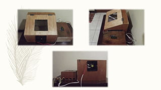
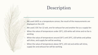
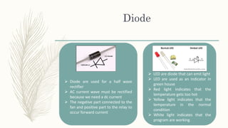
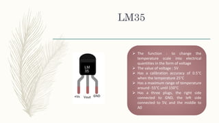
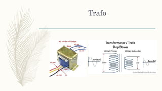
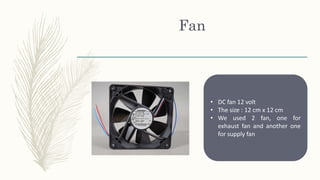
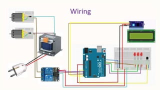
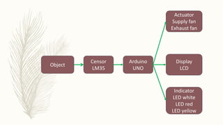
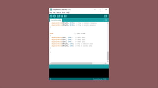
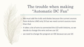
made by ;
M. Daddy Refa Manreza 151611015
Nurlatifa Haulaini 151611019
Ronito Halason 151611027
Group 9
2A
D3 Teknik Pendingin dan Tata Udara
Politeknik Negeri Bandung
Automatic room temperature controlled fan using arduino uno microcontrollerMohammod Al Emran
This paper presents the designs and the simulation of a DC fan control system based on room temperature using pulse width modulation technique, humidity and temperature sensor namely DHT11 with Arduino Uno Microcontroller. The fan will be used to reduce temperature of a room at certain level. To build the fan, we will use DTH11 Humidity Sensor. The sensor will measure the temperature continuously. When the temperature gets higher from a specific temperature, the fan will be on “On” mode. The speed of the fan will be determined by pwm using pulse-width modulation. The temperature along with the speed of the fan will be displayed through LCD monitor.
This document describes an automatic DC fan system using an LM35 temperature sensor that is controlled by an Arduino UNO. The system has two DC fans, one for exhaust and one for supply. It also has LED indicators and displays the temperature on an LCD. Based on the measured temperature from the LM35, the Arduino turns on the appropriate fans and LEDs. For example, if the temperature is below 20°C only the white LED is on, and between 26-29°C the supply fan is turned on along with white and yellow LEDs. The system aims to automatically control fans to regulate temperature in a greenhouse.
This paper presents an innovative prototype design of electric fan with smart characteristics. This electric fan uses a microcontroller to produce an automation function. It also has a unique double feature designs, such as using 2 fans, 2 Light Emitting Diodes (LED) and 2 sensors. This is to ensure the cooling process operates more efficiently and effectively, especially for a large space application and in hot weather due to global warming. By applying the circuit, it offers a better life for human. It is really practical for senior citizens to make their life simpler. The circuit is also suitable for disabled people who have difficulty to switch on the fan manually. Lastly, the circuit can be manipulated by diversifying its function as a detector, where it can produce an alarm signal when emergency case occurs such as the house or premise is on fire.
Temperature Based Fan Controller can be used for reducing the power consumption & also to assist people who are disabled and are unable to control the speed of fan.It may also be used for monitoring changes in environment.
DESIGN OF TEMPERATURE BASED FAN SPEED CONTROL and MONITORING USING ARDUINORatnesh Kumar chaurasia
This practical temperature controller controls the temperature of any device according to its requirement for any industrial application, it also has a feature of remote speed control.
Temperature monitoring and controling using arduinoBablu Singh
This document discusses the design of a temperature monitoring and controlling system using an Arduino microcontroller. It begins with an introduction to the motivation and objectives of the project, which are to automatically control cooling systems based on measured room temperature. It then discusses the hardware and software requirements, including using an Arduino board, LM35 temperature sensor, LCD display, relay, and connecting wires. The existing systems limitations with using an ATmega8 microcontroller are explained. The proposed system overview is given, which uses an Arduino microcontroller to address the limitations.
Temperature based fan speed control & monitoring usingJagannath Dutta
Our object of making this project is for reducing the power consumption. And also to assist people who are disabled and are unable to control the speed of fan.
This document describes a temperature control system using a PIC16F876A microcontroller, LM35 temperature sensors, and other components. The PIC reads the analog voltage from the LM35 sensors and displays the temperature on an LCD. When certain temperature thresholds are reached, the PIC activates fans, LEDs, and a buzzer using a power transistor. The system provides temperature monitoring and control capabilities. Source code and schematics are included to demonstrate the design and implementation.
This document describes an automatic temperature-controlled fan project using an Arduino Uno microcontroller. The fan will automatically turn on when the temperature reaches 35°C as measured by a temperature sensor, and will turn off again when the temperature drops below 35°C, in order to regulate the environment and reduce energy consumption. The system includes an Arduino, temperature sensor, LCD display, DC motor fan, battery power source, and connecting wires. Potential applications include use in homes and industries to assist people and save electricity by automating fan control based on temperature changes.
This project proposes automatic detection of human and energy saving room architecture to reduce standby power consumption and to make the temperature of the room easily controllable with an IR sensor and Lm35 temperature sensor using air conditioner . The proposed auto-detection of human done using the IR sensor to indicate the entering or exit ofthe persons. Microcontroller continuously monitors the infrared receiver. When any object pass throughthe IR receiver then the IR rays falling on the receiver are obstructed, this obstruction is sensed by the microcontroller ATMEGA16.When the temperature of the room is varied then the lm35 temperature sensor converts this temperature change into voltage which is then sensed by the microcontroller ATMEGA16 .
In such cases our project is aimed at starting one ac among both depending upon the temperature value at a particular room .If the temperature on the particular room is above certain range then the AC in that room will start up and during this time the AC in the other room will remain switched off. When the temperature goes below 25 degree in the room where AC is already on will be switched off automatically. Then if the temperature on the other room during the time is above 30degree then the AC in that room will start up and vice versa .The second feature of our project is aimed at switching of the AC automatically when there is absence of human beings in a particular room .The entire scheme is designed using number of ATMEGA16 microcontrollers , temperature sensors , digital counter ,IR sensors , relay etc.
This project will solve the day-to-day problem where AC’s do not start up due to low voltage generally in rural areas .This will start the AC depending upon the temperature label in a room by sharing the load .Also this project can be extended for controlling the temperature in more rooms in an apartment.
Automatic fan controller based on room temperaturenikhilreddy411
This document describes an automatic fan controller circuit that uses a thermistor and operational amplifier to monitor temperature. If the temperature exceeds a predefined limit, the thermistor sends a signal to the operational amplifier to activate a relay and fan, maintaining the temperature. Key components include a bridge rectifier, voltage regulator, thermistor, variable resistor, capacitor, transistor, diode, and relay. The circuit provides automatic fan control without human intervention to ensure cooling when temperatures rise.
Arduino based automatic temperature controlled fan speed regulatorEdgefxkits & Solutions
Using an analog temperature LM35 interfaced to the built in ADC of a programmed Arduino to develop varying duty cycle of PWM output for a driver IC to run a DC motor automatically according to the sensed temperature at different speed based on the temperature sensed.
This document describes how to use an Arduino board to read temperature data from an LM35 temperature sensor. It lists the necessary components as an LM35 temperature sensor, Arduino Uno, protoboard, and 3 wires. It provides images and brief descriptions of these components and gives an overview of the steps to set up the temperature sensing project, which include downloading and opening the Arduino software, copying code to read temperature from the LM35 sensor into the Arduino, and uploading the code to the board connected to a computer.
This document describes a temperature controlled fan project. It contains a block diagram showing the main components: an 8051 microcontroller, temperature sensor, ADC, motor driver, fan motor, and 7-segment displays. It also provides details on the working, which involves measuring temperature, displaying it on the 7-segment displays, and varying the fan speed based on the temperature using PWM. Simulation results and hardware implementation snapshots are included. The project aims to automatically control fan speed based on sensed temperature.
fan speed control by using temperature sensorNandeesh Boya
This document describes a fan control circuit that uses a temperature sensor. The circuit uses a thermistor temperature sensor that varies resistance based on temperature to control the speed of a DC fan. As temperature increases, fan speed increases to cool the area. The circuit aims to reduce power consumption by only running the fan as needed based on temperature. It could assist disabled individuals and be used for temperature monitoring and control in various industries.
This document describes the design and implementation of a temperature monitoring system. It includes a circuit diagram, block diagram, coding logic, algorithm, and flowchart. The system measures temperature using an ADC, converts the reading to Celsius, displays it on an LCD, and compares it to a threshold. If the temperature exceeds the threshold, an LED turns on. It records temperature samples at a user-defined interval to a flash memory. Applications include industrial temperature monitoring and fire alarm systems. The system was implemented on a microcontroller and FPGA for various projects.
This document describes an industrial temperature controller that uses a microcontroller and digital temperature sensor to control the temperature of a device. It displays the current, minimum, and maximum temperatures on an LCD screen and uses a relay connected to a heating element to maintain the temperature within the set limits. The controller requires components like a transformer, voltage regulator, capacitors, resistors, and transistors. It is intended to control temperature in industrial applications like manufacturing to maintain quality.
The document describes an automatic DC fan controller project using a thermistor. The project involves designing a circuit that can automatically control the speed of a DC fan based on temperature readings from a thermistor. The circuit uses an LM741 operational amplifier, NTC thermistor, resistors, and other components. As temperature increases, the thermistor's resistance decreases, causing the fan speed to increase accordingly to regulate the temperature. The document provides details of the circuit design and components, working principle, testing and potential applications of the automatic temperature-controlled fan system.
This project displays the current time and temperature using an Arduino board, LM35 temperature sensor, and DS1307 RTC module. The LM35 and DS1307 are connected to analog pins on the Arduino, which uses its onboard ADC to read the analog voltage values and display the converted time and temperature readings on an LCD screen. The key components required are the Arduino, sensors, LCD, and supporting electronics. The document provides details on how each component functions and how they interconnect and cooperate to continuously display the time and surrounding temperature.
temperature dependent dc fan speed controller withou using micrcontrollerDeepak Yadav
This document describes the development of an automatic fan system that controls fan speed based on room temperature. It uses a LM35 temperature sensor to detect temperature changes and an LM3914 integrated circuit to automatically adjust the fan speed through relays. The system aims to enable automatic fan speed control, develop an automatic fan system that changes speed according to temperature, and allow users to view the temperature and speed status on an LCD display. It works by sensing temperature with the LM35 sensor and sending the output to the LM3914 IC, which activates relays to change the fan speed as the temperature rises or falls.
This document describes an automatic fan and light controller project that uses a microcontroller to monitor temperature and light intensity in order to control a fan and lamp. It aims to reduce power consumption and assist disabled people. The system uses an Arduino board connected to sensors to measure temperature and light and control appliances via relays. It was found to potentially save 40% of energy consumption compared to uncontrolled fans and lights. The economic analysis showed the system would pay for itself within 6 months.
Temperature based speed control of fan using microcontrollerÇdh Suman
This document describes a temperature control project using an LM35 temperature sensor, ATMEGA32 microcontroller, DC motor, and other components. It uses pulse width modulation (PWM) to control the speed of the DC motor based on temperature readings from the LM35 sensor. The temperature readings are taken with the microcontroller's analog-to-digital converter and used to generate the PWM output that controls the motor driver and DC motor speed. The document outlines the components, methodology including a flow chart, and software implementation on the microcontroller. Applications mentioned include temperature control in computers, exhaust fans, washing machines, and CD/DVD players.
This document describes an automatic temperature control system using an 8085 microprocessor. The system uses an AD590 temperature sensor, differential amplifier, ADC0808 converter, and 8085 microprocessor to monitor and control the temperature. It aims to minimize manual intervention and control temperature in industrial plants. The system works by comparing the measured temperature to upper and lower setpoints and turning the heater or cooler on/off accordingly to maintain the temperature within the limits.
This document presents a mini project on an automatic temperature controlled fan. It includes an introduction, block diagram, components used, power supply details, and an introduction to the microcontroller used - PIC16F72. The system uses an LM35 temperature sensor, PIC microcontroller, DC fan driver circuit, resistors, diodes, capacitors, and voltage regulator. It regulates fan speed automatically based on temperature readings from the LM35 sensor through PWM control of the fan's driver circuit.
This document describes a temperature controller project using a PIC microcontroller. It controls temperature by varying the firing angle of a thyristor to adjust AC power levels from 1-100%. A K-type thermocouple measures temperature and its output is amplified before being read by the PIC. The PIC detects zero crossings to determine when to trigger the triac using a TRIAC firing angle control circuit. The system aims to control temperature in applications like ovens and furnaces.
This document describes an automatic DC fan system using an Arduino, LM35 temperature sensor, LCD display, and DC fans for controlling temperature in a greenhouse. The LM35 measures temperature and the Arduino controls DC fans and LED indicators based on temperature readings. If temperature is below 20°C, a white LED turns on and fans are off. Between 26-29°C, white and yellow LEDs turn on and a supply fan operates. Above 30°C, red and white LEDs turn on and both supply and exhaust fans operate. The system aims to automatically regulate greenhouse temperature.
This document describes an automatic DC fan system using an LM35 temperature sensor that is controlled by an Arduino UNO. The system has two DC fans, one for exhaust and one for supply. Based on the temperature readings from the LM35, different LED lights will illuminate and the fans will turn on/off accordingly to regulate the temperature. The document lists the components used, including the Arduino, LM35, LCD display, LEDs, fans, relays, and other electronic parts. It also provides diagrams of the circuit and describes some of the challenges faced in constructing the system.
Group members designed and implemented a temperature detection and control circuit using an Arduino, LM35 temperature sensor, LEDs, buzzer, LCD display, and DC fan motor. The LM35 sensor measures temperature and the output is displayed on the LCD. Different LEDs will illuminate according to different temperature ranges. If temperature exceeds 35 degrees, the buzzer will alert and the fan will turn on to cool down the environment. This circuit can monitor temperature in industrial applications and protect machinery from overheating.
This document describes a water level indicator system with a temperature sensor. The system monitors the water level in a crucible used for heating water and alerts if the level exceeds the limit. It also monitors the temperature in a heat tank using an LM35 temperature sensor to ensure it does not exceed the safe limit for steam generation. The system uses an Arduino Uno microcontroller along with LEDs, an LCD display, temperature sensor, pushbutton, and buzzer. It indicates the water level visually with LEDs and provides temperature readings in both Celsius and Fahrenheit on the LCD screen. An audible alarm from the buzzer alerts if the water level exceeds the limit.
This document describes a smart home system that automatically controls fan speed and lighting based on temperature and light intensity readings. The system uses a microcontroller, LCD display, temperature sensor, light sensor, motor driver, and relays to vary the fan speed based on room temperature between 25-45 degrees Celsius and switch lights on/off based on light intensity above or below 150 units. It also tracks the number of people in the room and turns everything off when unoccupied to save power.
Batch 12(temperature based fan speed control & monitor)gourishettyvivek
This document describes a student project to create a temperature-based fan speed control and monitoring system. The objectives are to measure room temperature, display the current temperature on an LCD screen, and vary the speed of a fan accordingly to reduce power consumption. The system uses an Arduino Uno microcontroller, LM35 temperature sensor, LCD display, and DC motor. As temperature increases, the fan speed increases automatically to control the room temperature. This project aims to automatically control fan speed based on temperature readings without manual intervention.
This document discusses various topics related to embedded systems including microcontrollers versus microprocessors, interfacing components like LEDs and LCDs, programming concepts like for loops and if statements, and examples of embedded systems like a digital clock and temperature sensor. It provides code examples in C programming language to interface different components and displays output screenshots.
The document discusses embedded systems and various electronic components used in microcontrollers like the Arduino, including inputs such as light sensors, outputs such as LEDs, and concepts such as analog and digital signals. It provides examples of how microcontrollers can read input from sensors in the environment and control outputs to devices. The Arduino IDE and programming concepts are also introduced as tools for writing code to operate microcontrollers and connected electronics.
Wireless greenhouse environment monitoring through sensorsSudhanshu Tripathi
This document describes a wireless greenhouse environment monitoring system using sensors. The system monitors temperature, humidity, soil moisture, and light intensity using various sensors and sends the data to a microcontroller. The microcontroller then controls actuators like water pumps, sprayers, and lights depending on the sensor readings and predefined thresholds. It uses sensors, a microcontroller, LCD display, and RF transmission to monitor and control devices in the greenhouse remotely.
International Journal of Engineering Research and DevelopmentIJERD Editor
Electrical, Electronics and Computer Engineering,
Information Engineering and Technology,
Mechanical, Industrial and Manufacturing Engineering,
Automation and Mechatronics Engineering,
Material and Chemical Engineering,
Civil and Architecture Engineering,
Biotechnology and Bio Engineering,
Environmental Engineering,
Petroleum and Mining Engineering,
Marine and Agriculture engineering,
Aerospace Engineering.
This document describes a home temperature control system using a microcontroller. It contains sections on the introduction, how it works, advantages, applications, power supply, components used including an ADC, LCD, temperature sensor, motor driver, and program flow. The system uses these components to measure temperature using a sensor, display it on an LCD, and control a fan motor based on the temperature reading.
Temperature based fan speed control & monitoring usingJagannath Dutta
Our object of making this project is for reducing the power consumption. And also to assist people who are disabled and are unable to control the speed of fan.
This document describes a temperature controlled fan speed controller circuit. The circuit uses an LM35 temperature sensor to monitor temperature. It sends the analog temperature reading to an ADC which converts it to a digital signal for a microcontroller. The microcontroller compares the temperature to set limits and controls the speed of a DC fan motor using PWM to vary the duty cycle and fan speed. It aims to efficiently cool components by increasing fan speed as temperature rises and decreasing it as temperature falls.
Smart under and over voltage protection system forShuvadip das
This project designs a smart home protection system that automatically turns the main power supply on and off in the case of under voltage or over voltage issues. The system uses a microcontroller to monitor the voltage levels and control a relay that switches the power. It includes a voltage sensor to measure the AC voltage, regulators to produce stable voltages for the components, and an LCD to display the voltage readings and system status. The circuit diagram and code are provided to demonstrate how it works and protect home devices from voltage issues without manual intervention.
The document describes the design of a multimeter using VHDL. The multimeter will have four modes - voltmeter, ammeter, ohmmeter, and beta calculator. It will use an Altera DE2 board programmed with VHDL code to control the logic and display measurements on LEDs and an LCD. The VHDL code will control the states and registers to manipulate the different modes. Additional circuits including a power supply, integrating amplifier, and resistance circuits will be used to measure voltage, current, resistance, and beta. Work has begun on the VHDL code and circuit designs, while future work includes completing the circuit designs and testing the integrated system.
Emotional Stress Indicator and Digital Thermometer-Project-8thsemkaushikbandopadhyay
This document outlines the contents and design of an emotional stress indicator and digital thermometer circuit. It includes sections on the introduction, methodology, circuit design, components used, operation of components, observations and conclusions for each project. The emotional stress indicator circuit measures changes in skin resistance to detect stress levels, while the digital thermometer circuit uses a temperature sensor and microcontroller to directly display temperature readings on an LED screen. Both circuits were successfully tested and achieved their objectives of measuring stress and temperature, respectively.
Automated Air Cooled Three Level Inverter system using ArduinoIJEEE
The output voltage of a three level inverter is stepped voltage in which the output voltage have three possible values. Such systems can be used to interface renewable energy sources with the grid. Temperature has significant effect on performance of power MOSFETs. Typically, the MOSFETs used as power switches in such applications are a significant source of heat, and the heat energy dissipated by these components must be carefully controlled if operating temperatures are to be maintained. So for the system to work efficiently cooling of MOSFETs is required. This paper proposed an automated air cooled 3 level H-bridge inverter. The system consists of MOSFETs, LM 35 temperature sensor, Optocouplers for isolation. Arduino is used to control the on-off operation of fan. When temperature rises above certain level fan turns on to cool the MOSFETs.
final Year Projects, Final Year Projects in Chennai, Software Projects, Embedded Projects, Microcontrollers Projects, DSP Projects, VLSI Projects, Matlab Projects, Java Projects, .NET Projects, IEEE Projects, IEEE 2009 Projects, IEEE 2009 Projects, Software, IEEE 2009 Projects, Embedded, Software IEEE 2009 Projects, Embedded IEEE 2009 Projects, Final Year Project Titles, Final Year Project Reports, Final Year Project Review, Robotics Projects, Mechanical Projects, Electrical Projects, Power Electronics Projects, Power System Projects, Model Projects, Java Projects, J2EE Projects, Engineering Projects, Student Projects, Engineering College Projects, MCA Projects, BE Projects, BTech Projects, ME Projects, MTech Projects, Wireless Networks Projects, Network Security Projects, Networking Projects, final year projects, ieee projects, student projects, college projects, ieee projects in chennai, java projects, software ieee projects, embedded ieee projects, "ieee2009projects", "final year projects", "ieee projects", "Engineering Projects", "Final Year Projects in Chennai", "Final year Projects at Chennai", Java Projects, ASP.NET Projects, VB.NET Projects, C# Projects, Visual C++ Projects, Matlab Projects, NS2 Projects, C Projects, Microcontroller Projects, ATMEL Projects, PIC Projects, ARM Projects, DSP Projects, VLSI Projects, FPGA Projects, CPLD Projects, Power Electronics Projects, Electrical Projects, Robotics Projects, Solor Projects, MEMS Projects, J2EE Projects, J2ME Projects, AJAX Projects, Structs Projects, EJB Projects, Real Time Projects, Live Projects, Student Projects, Engineering Projects, MCA Projects, MBA Projects, College Projects, BE Projects, BTech Projects, ME Projects, MTech Projects, M.Sc Projects, Final Year Java Projects, Final Year ASP.NET Projects, Final Year VB.NET Projects, Final Year C# Projects, Final Year Visual C++ Projects, Final Year Matlab Projects, Final Year NS2 Projects, Final Year C Projects, Final Year Microcontroller Projects, Final Year ATMEL Projects, Final Year PIC Projects, Final Year ARM Projects, Final Year DSP Projects, Final Year VLSI Projects, Final Year FPGA Projects, Final Year CPLD Projects, Final Year Power Electronics Projects, Final Year Electrical Projects, Final Year Robotics Projects, Final Year Solor Projects, Final Year MEMS Projects, Final Year J2EE Projects, Final Year J2ME Projects, Final Year AJAX Projects, Final Year Structs Projects, Final Year EJB Projects, Final Year Real Time Projects, Final Year Live Projects, Final Year Student Projects, Final Year Engineering Projects, Final Year MCA Projects, Final Year MBA Projects, Final Year College Projects, Final Year BE Projects, Final Year BTech Projects, Final Year ME Projects, Final Year MTech Projects, Final Year M.Sc Projects, IEEE Java Projects, ASP.NET Projects, VB.NET Projects, C# Projects, Visual C++ Projects, Matlab Projects, NS2 Projects, C Projects, Microcontroller Projects, ATMEL Projects, PIC Projects, ARM Projects, DSP Projects, VLSI Projects, FPGA Projects, CPLD Projects, Power Electronics Projects, Electrical Projects, Robotics Projects, Solor Projects, MEMS Projects, J2EE Projects, J2ME Projects, AJAX Projects, Structs Projects, EJB Projects, Real Time Projects, Live Projects, Student Projects, Engineering Projects, MCA Projects, MBA Projects, College Projects, BE Projects, BTech Projects, ME Projects, MTech Projects, M.Sc Projects, IEEE 2009 Java Projects, IEEE 2009 ASP.NET Projects, IEEE 2009 VB.NET Projects, IEEE 2009 C# Projects, IEEE 2009 Visual C++ Projects, IEEE 2009 Matlab Projects, IEEE 2009 NS2 Projects, IEEE 2009 C Projects, IEEE 2009 Microcontroller Projects, IEEE 2009 ATMEL Projects, IEEE 2009 PIC Projects, IEEE 2009 ARM Projects, IEEE 2009 DSP Projects, IEEE 2009 VLSI Projects, IEEE 2009 FPGA Projects, IEEE 2009 CPLD Projects, IEEE 2009 Power Electronics Projects, IEEE 2009 Electrical Projects, IEEE 2009 Robotics Projects, IEEE 2009 Solor Projects, IEEE 2009 MEMS Projects, IEEE 2009 J2EE P
This document provides information about interfacing a microcontroller with an LCD display and an ADC0804 analog-to-digital converter. It discusses the features of the LCD, including its ability to display text and graphics using an internal refresh controller. It also outlines the pin descriptions and functions of the ADC0804, such as its 8-bit resolution, voltage reference inputs, and output data pins. Finally, it explains the step-by-step conversion process for the ADC0804, which involves initiating a conversion with the WR pin and reading the output data after the INTR pin indicates the conversion is complete.
Similar to Automatic DC Fan using LM35 (english version) (20)
Digital Twins Computer Networking Paper Presentation.pptxaryanpankaj78
A Digital Twin in computer networking is a virtual representation of a physical network, used to simulate, analyze, and optimize network performance and reliability. It leverages real-time data to enhance network management, predict issues, and improve decision-making processes.
Optimizing Gradle Builds - Gradle DPE Tour Berlin 2024Sinan KOZAK
Sinan from the Delivery Hero mobile infrastructure engineering team shares a deep dive into performance acceleration with Gradle build cache optimizations. Sinan shares their journey into solving complex build-cache problems that affect Gradle builds. By understanding the challenges and solutions found in our journey, we aim to demonstrate the possibilities for faster builds. The case study reveals how overlapping outputs and cache misconfigurations led to significant increases in build times, especially as the project scaled up with numerous modules using Paparazzi tests. The journey from diagnosing to defeating cache issues offers invaluable lessons on maintaining cache integrity without sacrificing functionality.
DEEP LEARNING FOR SMART GRID INTRUSION DETECTION: A HYBRID CNN-LSTM-BASED MODELijaia
As digital technology becomes more deeply embedded in power systems, protecting the communication
networks of Smart Grids (SG) has emerged as a critical concern. Distributed Network Protocol 3 (DNP3)
represents a multi-tiered application layer protocol extensively utilized in Supervisory Control and Data
Acquisition (SCADA)-based smart grids to facilitate real-time data gathering and control functionalities.
Robust Intrusion Detection Systems (IDS) are necessary for early threat detection and mitigation because
of the interconnection of these networks, which makes them vulnerable to a variety of cyberattacks. To
solve this issue, this paper develops a hybrid Deep Learning (DL) model specifically designed for intrusion
detection in smart grids. The proposed approach is a combination of the Convolutional Neural Network
(CNN) and the Long-Short-Term Memory algorithms (LSTM). We employed a recent intrusion detection
dataset (DNP3), which focuses on unauthorized commands and Denial of Service (DoS) cyberattacks, to
train and test our model. The results of our experiments show that our CNN-LSTM method is much better
at finding smart grid intrusions than other deep learning algorithms used for classification. In addition,
our proposed approach improves accuracy, precision, recall, and F1 score, achieving a high detection
accuracy rate of 99.50%.
Discover the latest insights on Data Driven Maintenance with our comprehensive webinar presentation. Learn about traditional maintenance challenges, the right approach to utilizing data, and the benefits of adopting a Data Driven Maintenance strategy. Explore real-world examples, industry best practices, and innovative solutions like FMECA and the D3M model. This presentation, led by expert Jules Oudmans, is essential for asset owners looking to optimize their maintenance processes and leverage digital technologies for improved efficiency and performance. Download now to stay ahead in the evolving maintenance landscape.
Software Engineering and Project Management - Introduction, Modeling Concepts...Prakhyath Rai
Introduction, Modeling Concepts and Class Modeling: What is Object orientation? What is OO development? OO Themes; Evidence for usefulness of OO development; OO modeling history. Modeling
as Design technique: Modeling, abstraction, The Three models. Class Modeling: Object and Class Concept, Link and associations concepts, Generalization and Inheritance, A sample class model, Navigation of class models, and UML diagrams
Building the Analysis Models: Requirement Analysis, Analysis Model Approaches, Data modeling Concepts, Object Oriented Analysis, Scenario-Based Modeling, Flow-Oriented Modeling, class Based Modeling, Creating a Behavioral Model.
Electric vehicle and photovoltaic advanced roles in enhancing the financial p...IJECEIAES
Climate change's impact on the planet forced the United Nations and governments to promote green energies and electric transportation. The deployments of photovoltaic (PV) and electric vehicle (EV) systems gained stronger momentum due to their numerous advantages over fossil fuel types. The advantages go beyond sustainability to reach financial support and stability. The work in this paper introduces the hybrid system between PV and EV to support industrial and commercial plants. This paper covers the theoretical framework of the proposed hybrid system including the required equation to complete the cost analysis when PV and EV are present. In addition, the proposed design diagram which sets the priorities and requirements of the system is presented. The proposed approach allows setup to advance their power stability, especially during power outages. The presented information supports researchers and plant owners to complete the necessary analysis while promoting the deployment of clean energy. The result of a case study that represents a dairy milk farmer supports the theoretical works and highlights its advanced benefits to existing plants. The short return on investment of the proposed approach supports the paper's novelty approach for the sustainable electrical system. In addition, the proposed system allows for an isolated power setup without the need for a transmission line which enhances the safety of the electrical network
Introduction- e - waste – definition - sources of e-waste– hazardous substances in e-waste - effects of e-waste on environment and human health- need for e-waste management– e-waste handling rules - waste minimization techniques for managing e-waste – recycling of e-waste - disposal treatment methods of e- waste – mechanism of extraction of precious metal from leaching solution-global Scenario of E-waste – E-waste in India- case studies.
AI for Legal Research with applications, toolsmahaffeycheryld
AI applications in legal research include rapid document analysis, case law review, and statute interpretation. AI-powered tools can sift through vast legal databases to find relevant precedents and citations, enhancing research accuracy and speed. They assist in legal writing by drafting and proofreading documents. Predictive analytics help foresee case outcomes based on historical data, aiding in strategic decision-making. AI also automates routine tasks like contract review and due diligence, freeing up lawyers to focus on complex legal issues. These applications make legal research more efficient, cost-effective, and accessible.
Comparative analysis between traditional aquaponics and reconstructed aquapon...bijceesjournal
The aquaponic system of planting is a method that does not require soil usage. It is a method that only needs water, fish, lava rocks (a substitute for soil), and plants. Aquaponic systems are sustainable and environmentally friendly. Its use not only helps to plant in small spaces but also helps reduce artificial chemical use and minimizes excess water use, as aquaponics consumes 90% less water than soil-based gardening. The study applied a descriptive and experimental design to assess and compare conventional and reconstructed aquaponic methods for reproducing tomatoes. The researchers created an observation checklist to determine the significant factors of the study. The study aims to determine the significant difference between traditional aquaponics and reconstructed aquaponics systems propagating tomatoes in terms of height, weight, girth, and number of fruits. The reconstructed aquaponics system’s higher growth yield results in a much more nourished crop than the traditional aquaponics system. It is superior in its number of fruits, height, weight, and girth measurement. Moreover, the reconstructed aquaponics system is proven to eliminate all the hindrances present in the traditional aquaponics system, which are overcrowding of fish, algae growth, pest problems, contaminated water, and dead fish.
1. AUTOMATIC DC
FAN USING LM35
Base on Arduino
for Green House
English version
made by :
M. Daddy Refa M (151611015)
Nurlatifa Haulaini (151611019)
Ronito Halason (151611027)
2.
3. Description
– We used LM35 as a temperature censor, the result of the measurements are
displayed on the LCD
– We used 2 DC Fan 12 volt, one for exhaust fan and another fan as a supply fan
– When the value of temperature under 20°C, LED white will shine and no fan is
working
– When the value of temperature around 26°C until 29°C, LED white and yellow
will shine, and supply fan will be working
– When the value of temperature above 30°C, LED red and white will shine,
supply fan and exhaust fan will be working
5. The Equipment
Arduino UNO
LED : white, red and
yellow
LCD
Diode
Resistor
Wire
Trafo
DC Fan 12 volt
PCB
Relay Module
Solder
LM35
6. Arduino UNO R3
Consists of :
14 pin digital input/output
6 input analog
Mikrokontroler ATmega328
Koneksi USB
Power jack
ICSP header
Reset button
Arduino UNO is a microcontroller
board based on ATmega328
7. Diode
Diode are used for a half wave
rectifier
AC current wave must be rectified
because we need a dc current
The negative part connected to the
fan and positive part to the relay to
occur forward current
LED are diode that can emit light
LED are used as an indicator in
green house
Red light indicates that the
temperature gets too hot
Yellow light indicates that the
temperature in the normal
condition
White light indicates that the
program are working
8. LM35
The function : to change the
temperature scale into electrical
quantities in the form of voltage
The value of voltage : 5V
Has a calibration accuracy of 0.5°C
when the temperature 25°C
Has a maximum range of temperature
around -55°C until 150°C
Has a three plugs, the right side
connected to GND, the left side
connected to 5V, and the middle to
A0
9. LCD
Liquid Crystal Display (LCD)
LCD is a flat panel display or other
electronic visual display that use the
light modulating properties of liquid
crystals.
• Consist 16 character and 2 row
• can be observe with a 4 bit mode or
8 bit mode
• Equipped with back light
• In this project, LCD use to display the
value of temperature
10. Resistor
Resistor is electronic component
that serve to hold electric current.
Because of electrical currents
connected to electric voltage so that
when voltage is passed across the
resistor, there will be a decrease in
that voltage.
12. Fan
• DC fan 12 volt
• The size : 12 cm x 12 cm
• We used 2 fan, one for
exhaust fan and another one
for supply fan
13. Relay Module
• Relay is switch are operated
electrically
• Relay has two electromechanical
components, witch consist of two
main parts they are electromagnetic
(coil) and mechanical (set contact
switches)
• Principle of electromagnetic relay
use to move the switch contacts so
that when the electric current is
small (low power), it can conduct
electricity with a higher voltage
20. To control the Arduino, we must input the program
by using software Arduino IDE. First we should adapt the
COM of the Arduino with our software. Then, we should
choose the same board between the Arduino and the
software . F.or example : Board Arduino Genuino, COM 3)
21. The trouble when making
“Automatic DC Fan”
– We must add the trafo and diodes because the current sources
from Arduino UNO only 5V but we need current sources more
than that
– It takes a lot of wire to connected the LCD with Arduino, so we
decide to change the wire and we use I2C
– we need to change the program on IDE because we use I2C