Downloaded 240 times


![Auto CAD 2d and 3d Notes
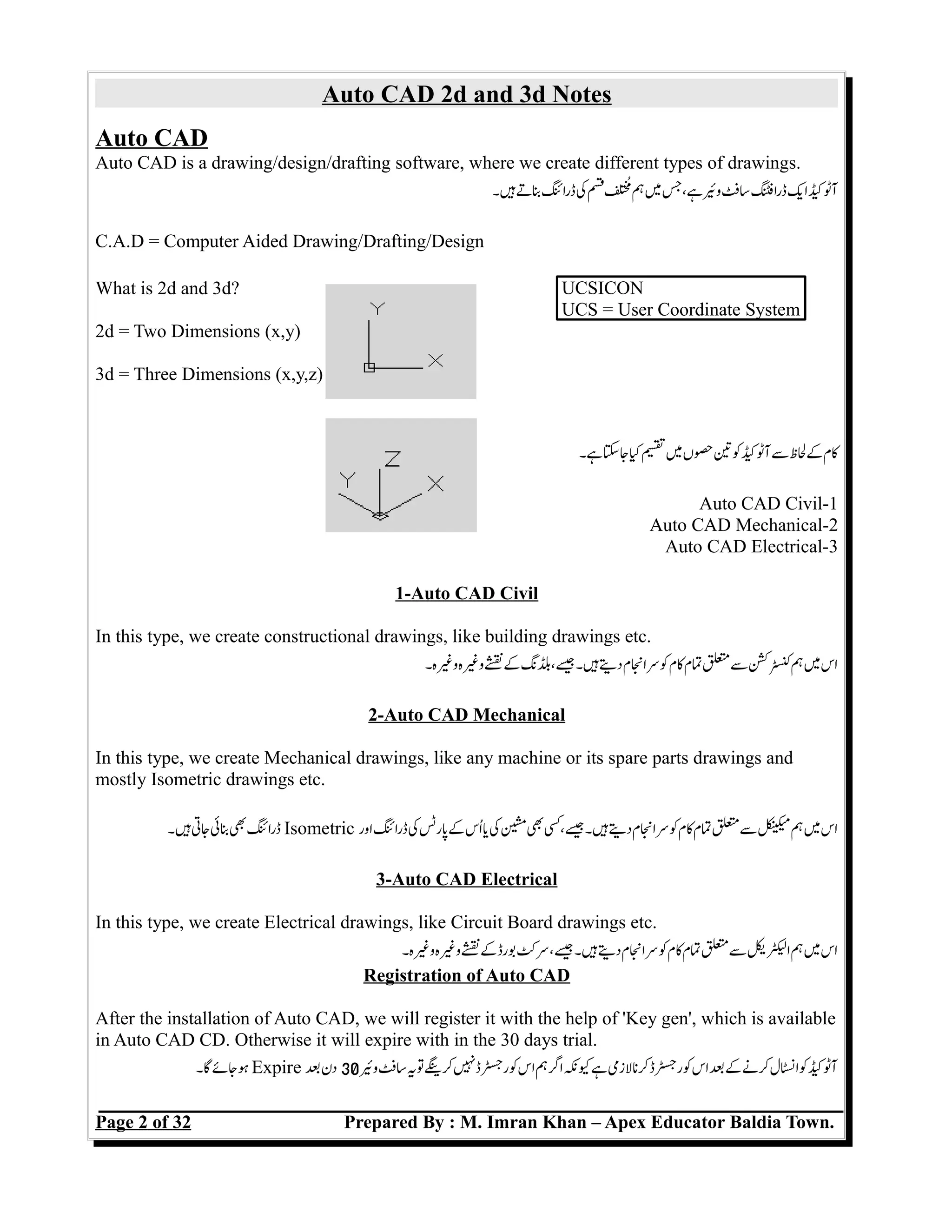
UCSICON:
It shows us that in which dimension we are working, either 2D or 3D. It should be fixed at the left
bottom corner of Auto CAD, other wise it will disturb us when we will Zooming our drawing.
ہ۔ہتلزمکنفطفکنجنبئکآٹککاس .r2D or 3D ہرہککممسکہکہبتکنہی
ہسکپاموقکتبایچٹکڈرائیورن۔
Method:
Command: UCSICON
Select an option[OFF/ON/All/Noorigin/ORigin/Properties]:
1- LINE (L):
We use this command to draw a line. Switch On ORHTO from status bar on Auto CAD or press
F8 to draw straight line.
سبرڈکعوہکاسہجتہ Active کنیسکنکپ ORTHO ہ۔جتکاسلکلبنکلئکنی
ہ۔تککمکنیسدبنکF8
Method:
Command: LINE (L)
From Point: (pick a point using the mouse)
(Pick a point using the mouse)
(Press return to end the command)
2- RECTANGLE (REC): (@50,60)---->(x,y)
We use this command to draw any Square Object, opposite sites are equal of this object.
ہ۔جتکبلئپلک Rectangle ہ۔ہتبابکدوسےایس˜لمدوکہ۔ججتکاسلکلبن Rectangle کنی
پائتمکاسکنہ۔ہتہےئممآپ
Method:
Command: Rectangle (REC)
RECTANG Chamfer/Elevation/Fillet/Thickness/Width/ <First corner>:
Pick first corner.
Pick other corner or type coordinates (@4,2).
3- EXPLODE (X):
We use this command to break any Rectangle or Poly line into lines.
ہجتکاسلککناسکتڑنمکلئRectangle ی Poly Line
Page 4 of 32 Prepared By : M. Imran Khan – Apex Educator Baldia Town.
Rectangle
x=4
x=4
y=2y=2
Line](https://image.slidesharecdn.com/autocad-160712041152/75/Auto-CAD-Notes-4-2048.jpg)

![Auto CAD 2d and 3d Notes
Method:
Command: CHAMFER (CHA)
Pick First object to chamfer.
Polyline/Distance/Angle/Trim/Method<Select first line>: select first object
Pick Second object to chamfer.
OR
Type One of the following options:
P Chamfers entire Polyline.
D Sets chamfer distances.
A Uses a distance and angle method instead of two distances.
T Sets the trim mode
E Sets the method to distance or angle.
7- TRIM (TR):
We use this command to trim line(s) to an exact intersection.
ہ۔جتکاسلکلکٹسمObject بککلئکنی
Method:
Command: TRIM (TR)
Click on line to extend
When extend done, press ESC button to exit.
TIP: Hold the SHIFT key to interactively extend instead of trim.
8- EXTEND (EX):
We use this command to extend line(s) to an outer object.
ہ۔جتکاسلکلبھنتObject بککلئکنی
Method:
Command: EXTEND (EX) [double enter]
Click on line to extend
When extend done, press ESC button to exit.
9- MOVE (M):
We use this command to move a any object to an exact location.
ہ۔جتکاسلکلدیحکجدوسیسجایکObject بککنی
Method:
Command: MOVE (M)
Pick Objects to move
Select objects: (select)
Pick A point to move from
Base point or displacement: (pick point)
Pick A point to move to
Second point of displacement: (pick point)
Page 6 of 32 Prepared By : M. Imran Khan – Apex Educator Baldia Town.](https://image.slidesharecdn.com/autocad-160712041152/75/Auto-CAD-Notes-6-2048.jpg)


![Auto CAD 2d and 3d Notes
Method:
25- INSERT (I):
We use this command to insert an Auto CAD drawing.
ہ۔جتکاسللکلنپScreen کڈرائک Auto CAD کنی
Method:
Command: INSERT (I):
Choose the Browse...to insert a drawing. Press OK.
Specify the insertion location by clicking on black screen.
26- LENTHEN (LEN):
We use this command o make changes in line, by Number, by Percentage, By Total and by
Dynamic method.
ہ۔جتکاسللککنتیسلظکby Number, by Percentage, By Total and by Dynamic مکنلئی
Method:
Command: LENGTHEN (LEN):
Select an object or [DElta/Percent/Total/Dynamic] <0.0000>:(enter any one option)
Select an object to change or [Undo]: pick object
ہ۔جسکاضفمسئککلئکجنکئمسئکلئسمدکاس :DELTA-1
ہ۔جسکبایذریچٹکفکلئسمدکاس :PERCENT-2
ہ۔سکتیبسنمسئمکلئہسمدکاس :TOTAL-3
ہ۔جسککسجبککلئسمدکاس :DYNAMIC-4
27- LINE TYPE (LT):
We use this command to change type line type of any object.
ہ۔جتکاسللککنتیکٹئلئکObject بکنکی
Method:
Command: LINE TYPE (LT): (Click on Load Button and choose Line Type)
Page 13 of 32 Prepared By : M. Imran Khan – Apex Educator Baldia Town.](https://image.slidesharecdn.com/autocad-160712041152/75/Auto-CAD-Notes-13-2048.jpg)


![Auto CAD 2d and 3d Notes
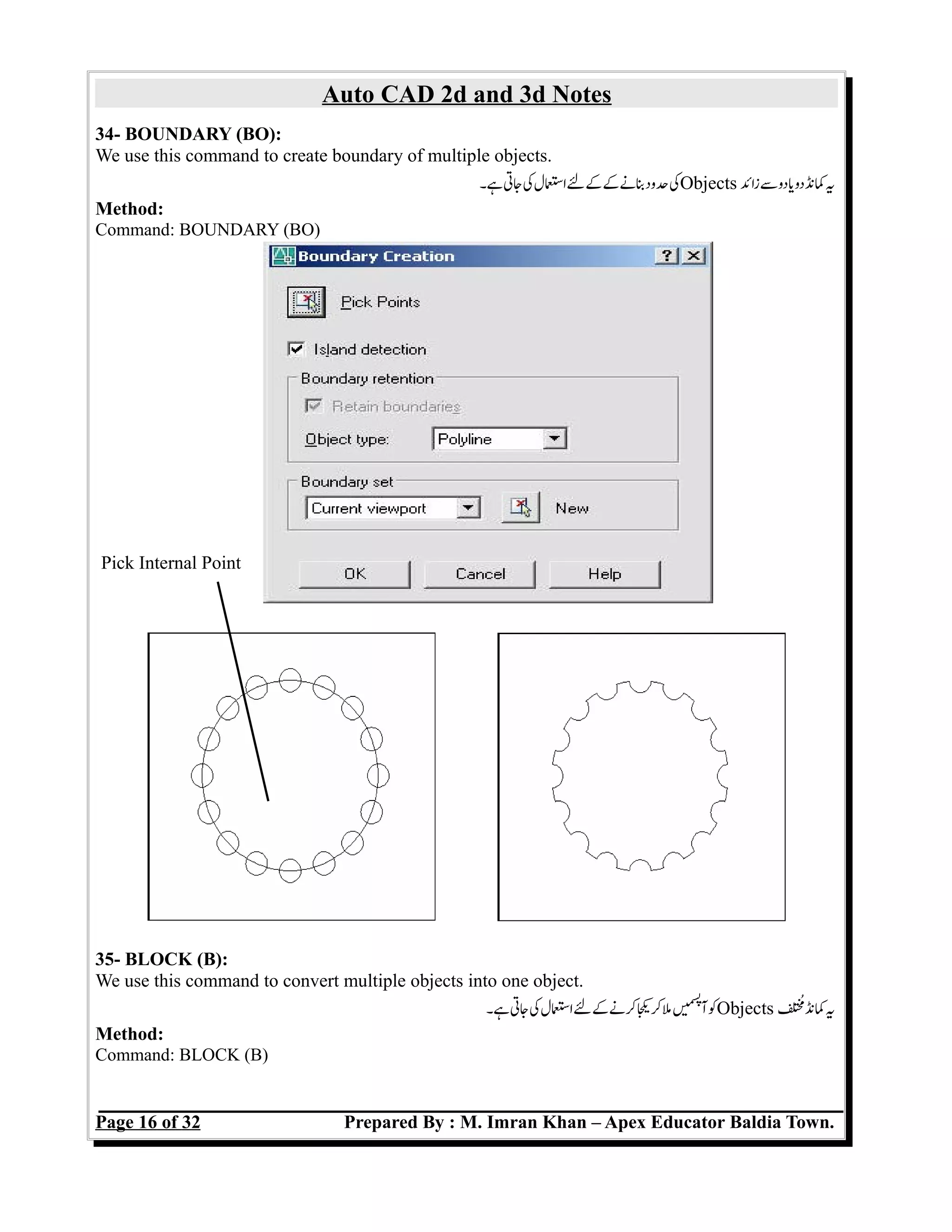
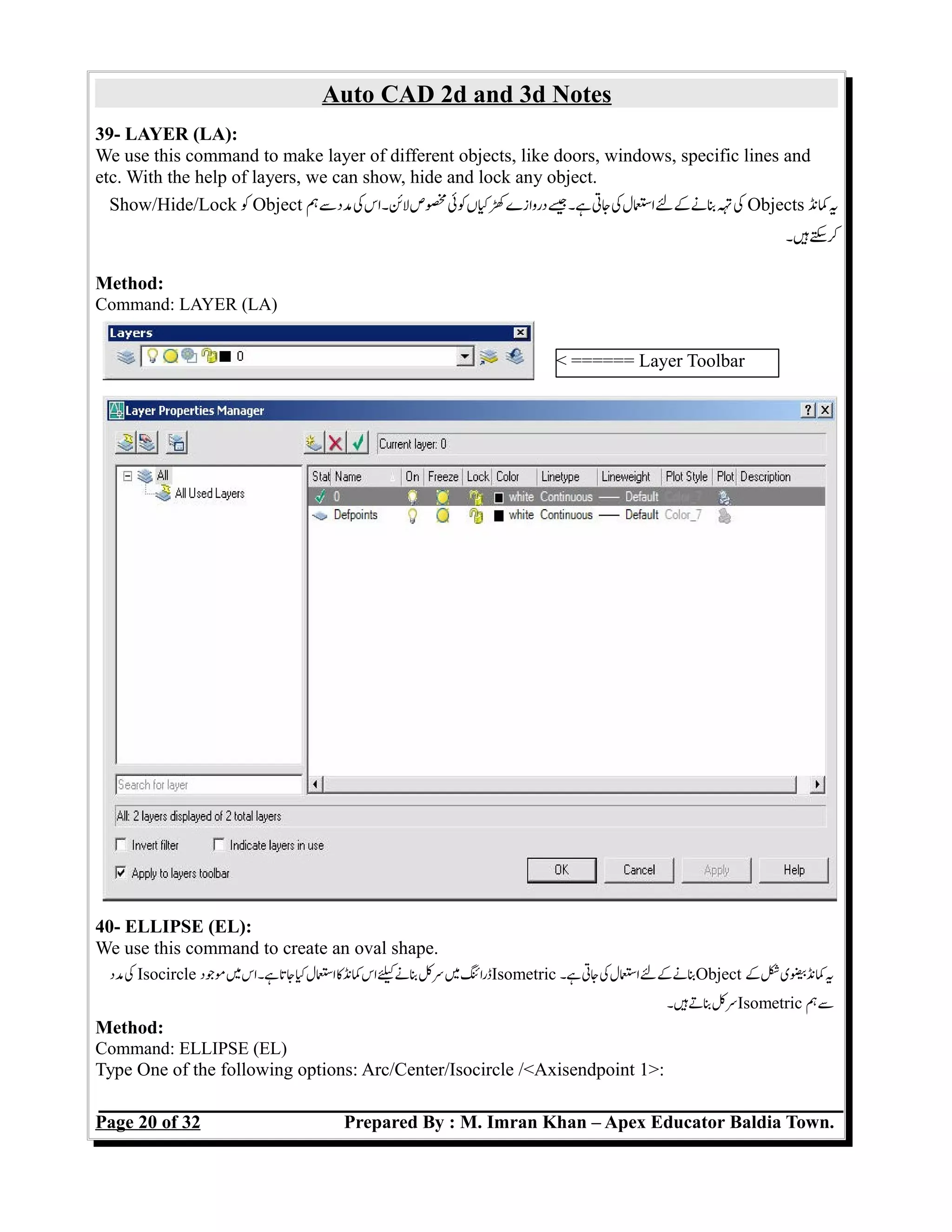
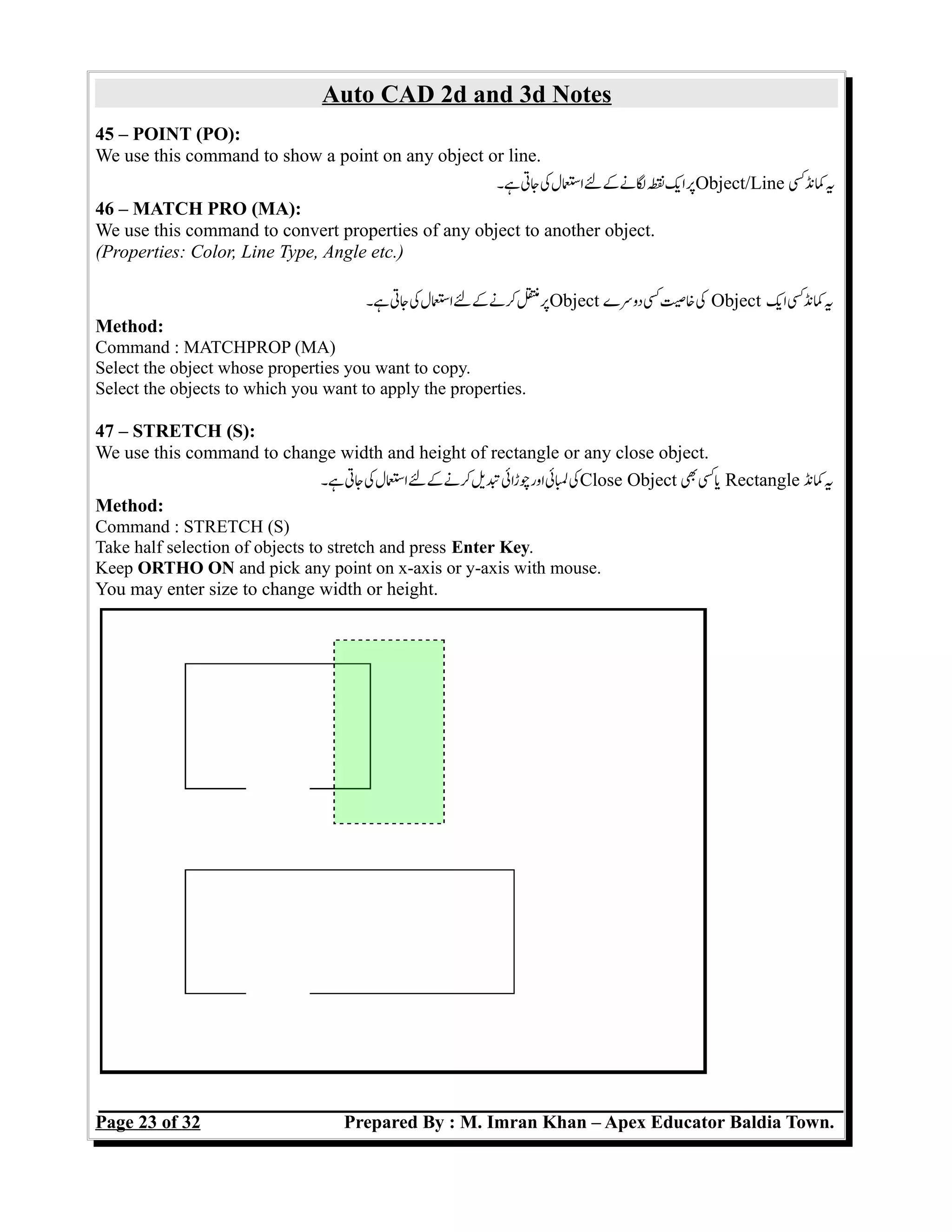
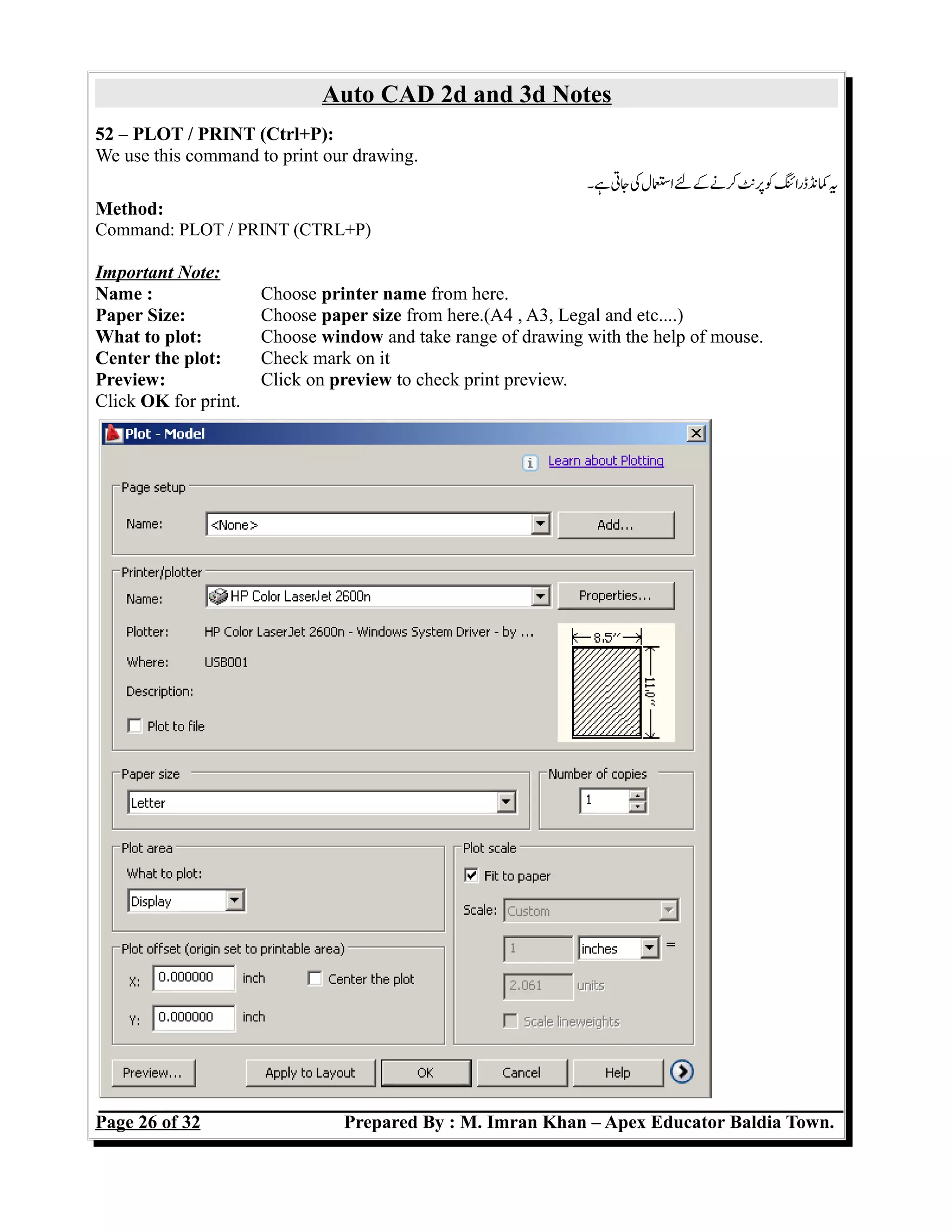
42 – POLY LINE (PL):
We use this command to create that line which all points are joined with each other. Also we can
create arrows, arc, and dark line.
ہ۔سببلئگیاورننکتعوہکہ۔اسہتہےئجےںeمیسپ
آپائتمجہسبلئوہہسمدککناس
Method:
Command : PLINE (PL)
Pick A point on the drawing to start the polyline
Type One of the following options Arc/Close/Halfwidth/Length/Undo/Width/<endpoint of line>:
43 – POLY EDIT (PE):
We use this command to join lines with each other with their points.
ہ۔جتکاسللکجڑنںeمیسپ
آکپائکلئںکنی
Method:
Command: PEDIT (PE)
Select Object [Multiple]: M (Press Enter) then Select Lines.
Type One of the following options:Close/Join/ Width/Edit vertex/FitCurve/Spline/Curve/
Decurve/Undo/eXit : (Choose “J” for join and press 03 times Enter key.)
44 – POLYGON (POL):
We use this command to create that object which have more than four (4) sides.
ہ۔ہتکرنزیسئزائسچرجہجتکاسلکبنکObject اسکنی
Method:
Polygon at the command prompt. Command: POLYGON
Number of sides <default>: (number)
Pick The center of the polygon. Edge/<Center of polygon>:
OR
Type E to define the polygon by two edges.
Type I or C to place the polygon inside or outside of an imaginary circle. Inscribed in
circle/Circumscribed about circle (I/C):
Edge Inscribed Circumscribed
Page 22 of 32 Prepared By : M. Imran Khan – Apex Educator Baldia Town.](https://image.slidesharecdn.com/autocad-160712041152/75/Auto-CAD-Notes-22-2048.jpg)
![Auto CAD 2d and 3d Notes
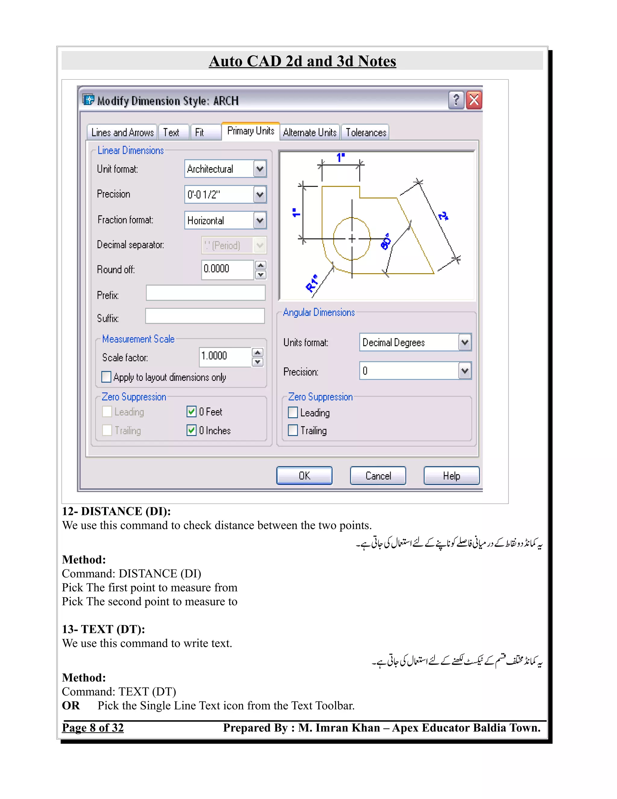
48 – CONSTRUCTION LINE / EXTRA LARGE LINE (XL):
We use this command to create unlimited line or create any shape with the help of object.
ہ۔جتکاسللکبنشکئسمدکObject کیبنلئلمودکنی
Method:
Command: XL
Specify a point or [Hor/Ver/Ang/Bisect/Offset]:
HOR: Creates a horizontal xline passing through a specified point.
VER: Creates a vertical xline passing through a specified point.
ANG: Creates an xline at a specified angle.
BISECT: Creates an xline that passes through the selected angle vertex and bisects the angle
between the first and second line.
OFFSET: Creates an xline parallel to another object.
49 – POLAR (F10):
We use this command to create a line with specif angle and line size.
ہ۔جتکاسللکبنسلئمدکسئکلئاورکنزاویی
Method:
Command: LINE (L)
Specify a point:(click on screen and switched on ORTHO):@1<0
Specify next point::@1<90
Specify next point::@1<180
Specify next point::@1<270
Page 24 of 32 Prepared By : M. Imran Khan – Apex Educator Baldia Town.](https://image.slidesharecdn.com/autocad-160712041152/75/Auto-CAD-Notes-24-2048.jpg)


![Auto CAD 2d and 3d Notes
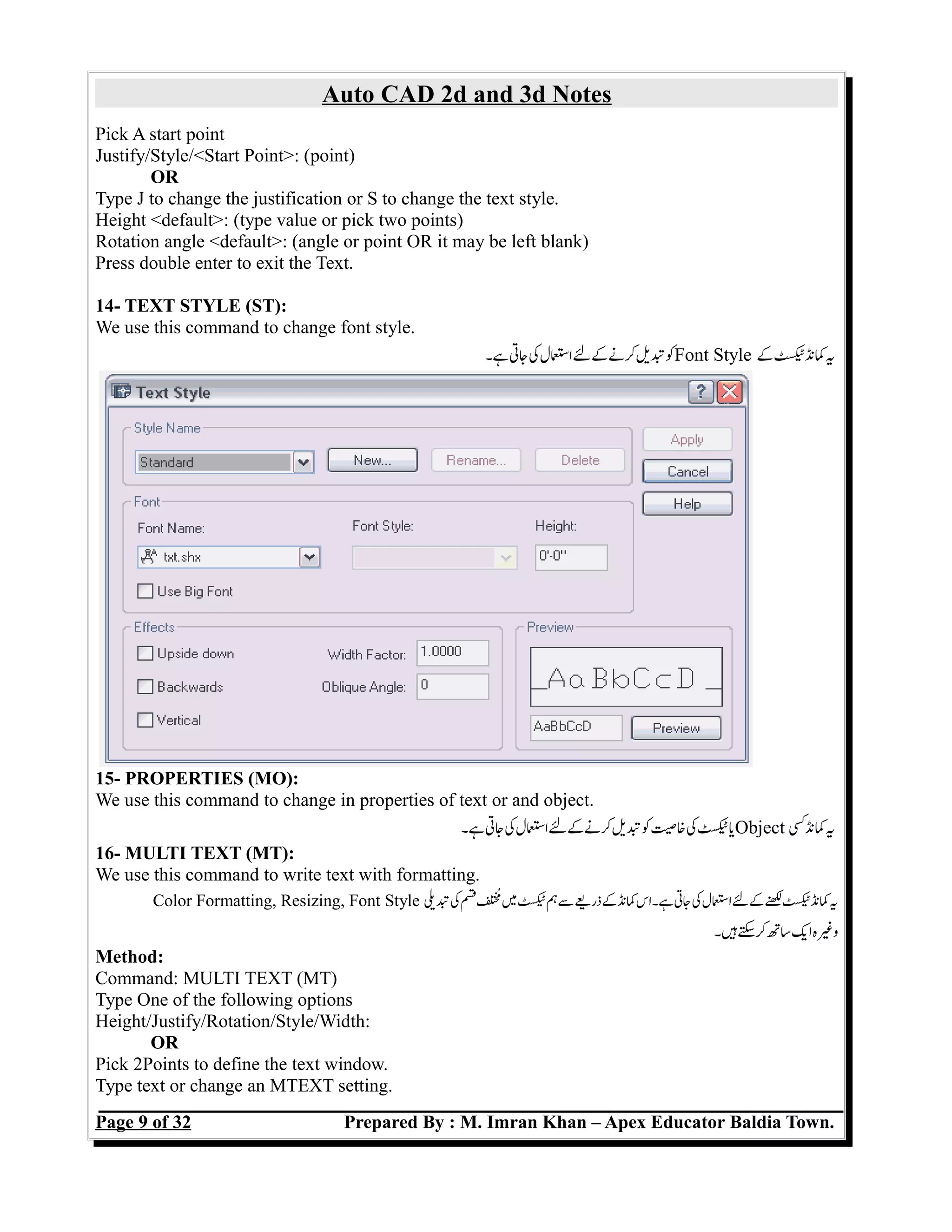
01 – EXTRUDE (EXT):
We use this command to create a solid object.
ہ۔لزمہنہاجاںeمیسپ
آکپائتممہاسجتکاسللکبنSolid Object کنی
Method:
Command: Extrude (Ext)
Select objects: (Enter)
Specify height of extrusion or [Direction/Path/Taper angle]:
Extrude with Taper
Method:
Command: Extrude (Ext)
Select objects: (Enter)
Specify height of extrusion or [Direction/Path/Taper angle]: T
Specify angle of taper for extrusion <0>: 15
Specify height of extrusion or [Direction/Path/Taper angle] <8.9509>: 4
Page 28 of 32 Prepared By : M. Imran Khan – Apex Educator Baldia Town.](https://image.slidesharecdn.com/autocad-160712041152/75/Auto-CAD-Notes-28-2048.jpg)
![Auto CAD 2d and 3d Notes
Extrude with Path
Method:
Command: Extrude (Ext)
Select objects: (Enter)
Specify height of extrusion or [Direction/Path/Taper angle]: P
Select extrusion path. (Line, Arc etc..)
02 – REGION (REG):
We use this command to to join arcs/circles and lines with each other.
ہ۔جتکاسللکجڑنںeمیسپ
آکArc اور Line کنی
Method:
Command REGION (REG)
Select Object: (Press Enter)
03 – SUBTRACT (SU):
We use this command to subtract object from another object.
ہ۔جتکاسللکنلسمObject دوسےکاسک Object ایکنی
Method:
Command: SUBTRACT (SU)
Select objects: pick the main box (Outer Box) Press enter
Select solids and regions to subtract...
Select objects: pick the other solids Select objects: enter
04 – UNION (UN):
We use this command to join multiple 3d objects.
ہ۔جتکاسللکجڑنںeمیسپ
آکSolid Objects زائسایکنی
Method:
Command: UNION (UN)
Select objects: Press Enter Key.
Page 29 of 32 Prepared By : M. Imran Khan – Apex Educator Baldia Town.](https://image.slidesharecdn.com/autocad-160712041152/75/Auto-CAD-Notes-29-2048.jpg)
![Auto CAD 2d and 3d Notes
05 – REVOLVE (REV):
We use this command to create object with an angle.
ہ۔جتکاسللکبنObject سمدکزاویکنی
Method:
Command: REVOLVE (REV)
Select objects : press enter
Specify start point for axis of revolution or define axis by [Object/X (axis)/Y (axis)]:select points
of axis.
Specify angle of revolution <360>: Specify angle or Press enter.
Page 30 of 32 Prepared By : M. Imran Khan – Apex Educator Baldia Town.](https://image.slidesharecdn.com/autocad-160712041152/75/Auto-CAD-Notes-30-2048.jpg)
![Auto CAD 2d and 3d Notes
Procedure for revolve.
First draw a circle. Draw a line from top to bottom in the circle. Trim the half part of circle, you
will get below mentioned shape.
Join both the object with each other with the help of Region(Command # 02 in 3d section).
Now, apply revolve command as mentioned above and you can get below mentioned shape.
Similarly, you can draw different object with the help of SPLine and Arcs. Which object you will
draw, it should be close and join like above shape, otherwise revolve command will not work.
06 – SLICE (SL):
We use this command to break a solid object into two parts.
ہ۔جتکاسللکتڑنمحںدوکSolid Object کنی
Method:
Command: SLICE (SL)
Select objects to slice: 1 found
Specify start point of slicing plane or [planar
Object/Surface/Zaxis/View/XY/YZ/ZX/3points] <3points>:
Specify a point on the YZ-plane <0,0,0>:
Specify a point on desired side or [keep Both sides] <Both>:
Page 31 of 32 Prepared By : M. Imran Khan – Apex Educator Baldia Town.](https://image.slidesharecdn.com/autocad-160712041152/75/Auto-CAD-Notes-31-2048.jpg)


The document provides notes on AutoCAD 2D and 3D. It discusses the different types of AutoCAD including Civil, Mechanical, and Electrical. It explains how to register AutoCAD after installation. It also outlines some common commands used in AutoCAD like LINE, RECTANGLE, EXPLODE, OFFSET, FILLET, and CHAMFER and provides brief descriptions of what each command is used for and its basic usage.