The document provides information about AutoCAD, including:
1. AutoCAD is 2D and 3D modeling software developed by Autodesk for computer aided design (CAD). It allows for precise drawing and modeling with benefits like improved productivity and accuracy.
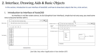
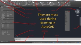
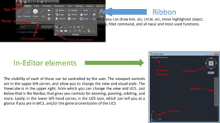
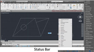
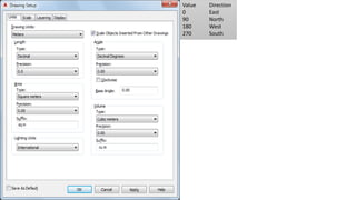
2. The interface of AutoCAD includes common elements like menus and ribbons as well as drafting specific tools. Drawing units and limits can be customized.
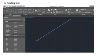
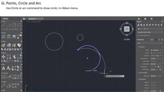
3. Basic objects in AutoCAD like lines, circles, and arcs can be created using commands in the ribbon. Selection tools allow objects on screen to be precisely selected.