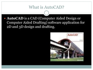
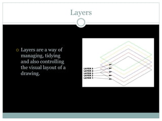
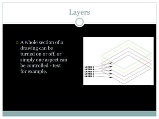
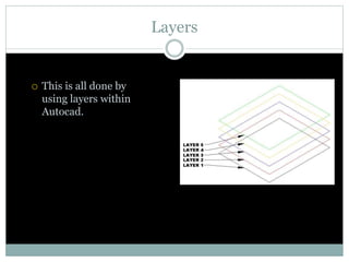
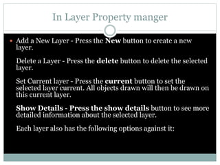
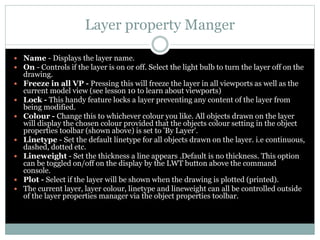
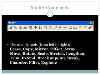
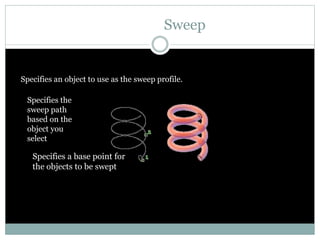
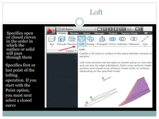
AUTO CAD
NATIONAL DESIGN SCHOOL
CIVIL ENGINEERING
SHAHEED BHAGAT SINGH STATE TECHNICAL CAMPUS
SUMBITTED TO : SUMBITTED BY :
Mr.BOHAR SINGH DEEPAK KUMAR
1421400
CIVIL ENGINEERING
BATCH (2014-2018)
What is AutoCAD?
 AutoCAD is a CAD (Computer Aided Design or
Computer Aided Drafting) software application for
2D and 3D design and drafting.
Commands
 Tool Bar
 Pull Down
 KEY COMMANDS
 From the Key board
Key Sequences
 Always look at the command line
 At the bottom of the page
 Always be as specific as possible
Layers
 In Auto CAD, we make individual layers…
 For things like
 Hidden lines
 Center lines
 Section lines
 Break lines
Layers
 Layers are a way of
managing, tidying
and also controlling
the visual layout of a
drawing.
Layers
 A whole section of a
drawing can be
turned on or off, or
simply one aspect can
be controlled - text
for example.
Layers
 This is all done by
using layers within
Autocad.
What is a Layer
 A layer can be thought of as a large piece of clear plastic, as
infinitely large as the drawing area in Autocad.
What is a Layer
 When drawing in Autocad, everything is drawn on the
default layer which is set current. Only the objects you are
drawing are visible on the layer, the layer itself can never
be seen - it is invisible.
What is a Layer
 Each new layer is created by you, the user. Normally, it is
acceptable to have a layer for each different part of a
drawing.
Layers are controlled by the layer properties manager button which is located on
the object properties toolbar:
Layer property manger
In Layer Property manger
 Add a New Layer - Press the New button to create a new
layer.
Delete a Layer - Press the delete button to delete the selected
layer.
Set Current layer - Press the current button to set the
selected layer current. All objects drawn will then be drawn on
this current layer.
Show Details - Press the show details button to see more
detailed information about the selected layer.
Each layer also has the following options against it:
Layer property Manger
 Name - Displays the layer name.
 On - Controls if the layer is on or off. Select the light bulb to turn the layer off on the
drawing.
 Freeze in all VP - Pressing this will freeze the layer in all viewports as well as the
current model view (see lesson 10 to learn about viewports)
 Lock - This handy feature locks a layer preventing any content of the layer from
being modified.
 Colour - Change this to whichever colour you like. All objects drawn on the layer
will display the chosen colour provided that the objects colour setting in the object
properties toolbar (shown above) is set to 'By Layer'.
 Linetype - Set the default linetype for all objects drawn on the layer. i.e continuous,
dashed, dotted etc.
 Lineweight - Set the thickness a line appears .Default is no thickness. This option
can be toggled on/off on the display by the LWT button above the command
console.
 Plot - Select if the layer will be shown when the drawing is plotted (printed).
 The current layer, layer colour, linetype and lineweight can all be controlled outside
of the layer properties manager via the object properties toolbar.
Drafting Settings
 Command DS
 Changes Grid
 Object Snaps
 Polar Tracking
Modify Commands
 The modify tools (from left to right):
Erase, Copy, Mirror, Offset, Array,
Move, Rotate, Scale, Stretch, Lengthen,
Trim, Extend, Break at point, Break,
Chamfer, Fillet, Explode
Erase
 Select this button then a drawing element to erase it
permanently from the drawing.
Copy
 Copy - The copy command will copy any selected
drawing elements and reposition where specified by
the user, without affecting the original elements.
Mirror
Mirror - The mirror command will create a
mirror image of any selected drawing
elements along any line of symmetry
specified by the user.
Offset
 Offset will make a copy of a line or series of
selected lines by a specified distance in the
direction specified.
Array
 The array command quickly creates copies of a
selected object(s) to a specified spacing..
Rectangular Array
Rectangular Array
Polar Array
Move
 The move command works exactly the same as the
copy command described above, except instead of
creating a copy of the selected objects, the second
objects are moved.
Rotate
 The rotate command rotates any selected objects
about a defined point by the angle specified. By
default Autocad will rotate objects anticlockwise
when an angle is entered.
Scale
 The scale command scales the size of a selected
object(s) by a defined scale factor from a selected
base point. The selected objects can be scaled up to
increase size or down to reduce the size.
Trim
 The trim command is an extremely useful tool
which will erase all parts of an object beyond
or within its intersection with another object.
Break
 The break command is identical to the break at point
command, except the break line isn't as neat as break
at point.
Chamfer
 The chamfer command will chamfer the intersection
of two lines to a specified distance.
Fillet
 The fillet command is very similar to the
chamfer command above, except instead of
creating a straight line chamfer, Autocad
creates a radius between the two points.
Zoom real time and Pan
 While holding the left mouse button, pull the
mouse to the left, right, up or down. Notice
how the pan tool reflects these mouse
movements on screen so we can move around
the screen effortlessly.
AutoCad 3D(Introduction)
Double click on
the AutoCAD
icon on the
windows
desktop.
Extrude
Now from the Home
Tab> modeling panel,
click Extrude. Follow
the instructions on the
command prompt i.e.
select the object and
click Enter.
At the SPECIFY
HEIGHT:
prompt, type
200 and click
Enter.
Extrude
Click on the
conceptual
style and see
how your
door looks
like.
Revolve
Select a closed object to revolve
lick to points on the screen to
set the axis orientation. The
axis points must be on one
side of the revolved object.
The positive axis direction
extends from the start point
to the endpoint.
The X, Y,
or Z axis. Enter x, y, or z
Sweep
Specifies an object to use as the sweep profile.
Specifies the
sweep path
based on the
object you
select
Specifies a base point for
the objects to be swept
Loft
Specifies open
or closed curves
in the order in
which the
surface or solid
will pass
through them
Specifies first or
last point of the
lofting
operation. If you
start with the
Point option,
you must next
select a closed
curve
AUTO CAD CIVIL ENGINEERING PPT REPORT

AUTO CAD CIVIL ENGINEERING PPT REPORT

  • 1.
    AUTO CAD NATIONAL DESIGNSCHOOL CIVIL ENGINEERING SHAHEED BHAGAT SINGH STATE TECHNICAL CAMPUS SUMBITTED TO : SUMBITTED BY : Mr.BOHAR SINGH DEEPAK KUMAR 1421400 CIVIL ENGINEERING BATCH (2014-2018)
  • 2.
    What is AutoCAD? AutoCAD is a CAD (Computer Aided Design or Computer Aided Drafting) software application for 2D and 3D design and drafting.
  • 3.
    Commands  Tool Bar Pull Down  KEY COMMANDS  From the Key board
  • 4.
    Key Sequences  Alwayslook at the command line  At the bottom of the page  Always be as specific as possible
  • 5.
    Layers  In AutoCAD, we make individual layers…  For things like  Hidden lines  Center lines  Section lines  Break lines
  • 6.
    Layers  Layers area way of managing, tidying and also controlling the visual layout of a drawing.
  • 7.
    Layers  A wholesection of a drawing can be turned on or off, or simply one aspect can be controlled - text for example.
  • 8.
    Layers  This isall done by using layers within Autocad.
  • 9.
    What is aLayer  A layer can be thought of as a large piece of clear plastic, as infinitely large as the drawing area in Autocad.
  • 10.
    What is aLayer  When drawing in Autocad, everything is drawn on the default layer which is set current. Only the objects you are drawing are visible on the layer, the layer itself can never be seen - it is invisible.
  • 11.
    What is aLayer  Each new layer is created by you, the user. Normally, it is acceptable to have a layer for each different part of a drawing. Layers are controlled by the layer properties manager button which is located on the object properties toolbar:
  • 12.
  • 13.
    In Layer Propertymanger  Add a New Layer - Press the New button to create a new layer. Delete a Layer - Press the delete button to delete the selected layer. Set Current layer - Press the current button to set the selected layer current. All objects drawn will then be drawn on this current layer. Show Details - Press the show details button to see more detailed information about the selected layer. Each layer also has the following options against it:
  • 14.
    Layer property Manger Name - Displays the layer name.  On - Controls if the layer is on or off. Select the light bulb to turn the layer off on the drawing.  Freeze in all VP - Pressing this will freeze the layer in all viewports as well as the current model view (see lesson 10 to learn about viewports)  Lock - This handy feature locks a layer preventing any content of the layer from being modified.  Colour - Change this to whichever colour you like. All objects drawn on the layer will display the chosen colour provided that the objects colour setting in the object properties toolbar (shown above) is set to 'By Layer'.  Linetype - Set the default linetype for all objects drawn on the layer. i.e continuous, dashed, dotted etc.  Lineweight - Set the thickness a line appears .Default is no thickness. This option can be toggled on/off on the display by the LWT button above the command console.  Plot - Select if the layer will be shown when the drawing is plotted (printed).  The current layer, layer colour, linetype and lineweight can all be controlled outside of the layer properties manager via the object properties toolbar.
  • 15.
    Drafting Settings  CommandDS  Changes Grid  Object Snaps  Polar Tracking
  • 16.
    Modify Commands  Themodify tools (from left to right): Erase, Copy, Mirror, Offset, Array, Move, Rotate, Scale, Stretch, Lengthen, Trim, Extend, Break at point, Break, Chamfer, Fillet, Explode
  • 17.
    Erase  Select thisbutton then a drawing element to erase it permanently from the drawing.
  • 18.
    Copy  Copy -The copy command will copy any selected drawing elements and reposition where specified by the user, without affecting the original elements.
  • 19.
    Mirror Mirror - Themirror command will create a mirror image of any selected drawing elements along any line of symmetry specified by the user.
  • 20.
    Offset  Offset willmake a copy of a line or series of selected lines by a specified distance in the direction specified.
  • 21.
    Array  The arraycommand quickly creates copies of a selected object(s) to a specified spacing..
  • 22.
  • 23.
  • 24.
  • 25.
    Move  The movecommand works exactly the same as the copy command described above, except instead of creating a copy of the selected objects, the second objects are moved.
  • 26.
    Rotate  The rotatecommand rotates any selected objects about a defined point by the angle specified. By default Autocad will rotate objects anticlockwise when an angle is entered.
  • 27.
    Scale  The scalecommand scales the size of a selected object(s) by a defined scale factor from a selected base point. The selected objects can be scaled up to increase size or down to reduce the size.
  • 28.
    Trim  The trimcommand is an extremely useful tool which will erase all parts of an object beyond or within its intersection with another object.
  • 29.
    Break  The breakcommand is identical to the break at point command, except the break line isn't as neat as break at point.
  • 30.
    Chamfer  The chamfercommand will chamfer the intersection of two lines to a specified distance.
  • 31.
    Fillet  The filletcommand is very similar to the chamfer command above, except instead of creating a straight line chamfer, Autocad creates a radius between the two points.
  • 32.
    Zoom real timeand Pan  While holding the left mouse button, pull the mouse to the left, right, up or down. Notice how the pan tool reflects these mouse movements on screen so we can move around the screen effortlessly.
  • 33.
    AutoCad 3D(Introduction) Double clickon the AutoCAD icon on the windows desktop.
  • 34.
    Extrude Now from theHome Tab> modeling panel, click Extrude. Follow the instructions on the command prompt i.e. select the object and click Enter. At the SPECIFY HEIGHT: prompt, type 200 and click Enter.
  • 35.
    Extrude Click on the conceptual styleand see how your door looks like.
  • 36.
    Revolve Select a closedobject to revolve lick to points on the screen to set the axis orientation. The axis points must be on one side of the revolved object. The positive axis direction extends from the start point to the endpoint. The X, Y, or Z axis. Enter x, y, or z
  • 37.
    Sweep Specifies an objectto use as the sweep profile. Specifies the sweep path based on the object you select Specifies a base point for the objects to be swept
  • 38.
    Loft Specifies open or closedcurves in the order in which the surface or solid will pass through them Specifies first or last point of the lofting operation. If you start with the Point option, you must next select a closed curve

Editor's Notes