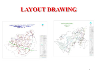
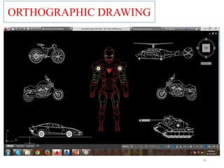
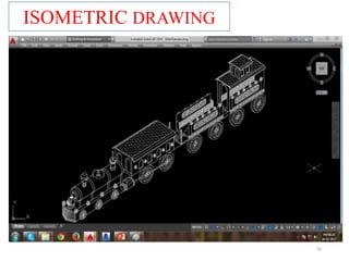
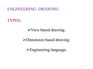
This document provides an overview of AutoCAD and its uses. It discusses what AutoCAD is, common projection and drawing types in AutoCAD like orthographic and isometric. It also covers CAD file formats, advantages of CAD, common CAD users, and engineering drawing types. Keyboard shortcuts and functions keys in AutoCAD are listed. Examples of civil engineering drawings created in AutoCAD like building drawings, center line plans, and layout drawings are also provided.


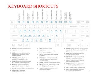
![Function Keys
• Function Keys provide instant access to commands
21
[F1] - Help
[F2] - Flip screen from graphics to text toggle On/Off
[F3] - Displays Osnap On/Off
[F4] - Displays 3D Osnap On/Off
[F5] - Isoplane (Left, Right, Top)
[F6] - Coordinate display
[F7] - Grid mode toggle On/Off
[F8] - Ortho mode toggle On/Off
[F9] - Snap mode toggle On/Off
[F10] - Polar Tracking mode toggle On/Off
[F11] – Object Snap Tracking On/Off
[F12] – Command Window Inter Change](https://image.slidesharecdn.com/autocadcivil-180216113436/85/Auto-CADD-civil-21-320.jpg)