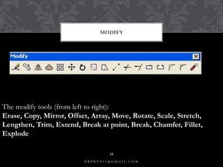
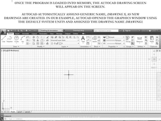
Presentation on basic Autocad tools
AUTO CAD
H R P R T 0 0 1 @ G M A I L . C O M
1
Auto Cad Introduction
Basic Drawing Tools
Modify Tools
Layers And Dimensions
Section Views and Blocks
3d Modelling
INDEX
H R P R T 0 0 1 @ G M A I L . C O M
2
AutoCAD is a commercial computer-aided design (CAD) and drafting
software application. Developed and marketed by Autodesk, AutoCAD was
first released in December 1982 as a desktop app running on microcomputers
with internal graphics controllers. Prior to the introduction of AutoCAD,
most commercial CAD programs ran on mainframe computers
or minicomputers, with each CAD operator (user) working at a
separate graphics terminal. Since 2010, AutoCAD was released as a mobile
and web app as well, marketed as AutoCAD 360.
AutoCAD is used across a wide range of industries, by architects, project
managers, engineers, graphic designers, and many other professionals. It was
supported by 750 training centers worldwide in 1994.
WHAT IS AUTO CAD
H R P R T 0 0 1 @ G M A I L . C O M
3
ONCE THE PROGRAM IS LOADED INTO MEMORY, THE AUTOCAD DRAWING SCREEN
WILL APPEAR ON THE SCREEN.
AUTOCAD AUTOMATICALLY ASSIGNS GENERIC NAME, DRAWING X, AS NEW
DRAWINGS ARE CREATED. IN OUR EXAMPLE, AUTOCAD OPENED THE GRAPHICS WINDOW USING
THE DEFAULT SYSTEM UNITS AND ASSIGNED THE DRAWING NAME DRAWING1.
H R P R T 0 0 1 @ G M A I L . C O M
4
THE AUTO CAD WINDOW
H R P R T 0 0 1 @ G M A I L . C O M
5
RIBBON BAR
The most prominent feature in the autocad besides the drawing area is the
ribbon. This is where user can selectthe tools to draw, edit or perform other
functions.The ribbon contains a set of panels representing groups of tools
and features. The name of each Ribbon panel is found in its title bar at the
bottom of the pannel
H R P R T 0 0 1 @ G M A I L . C O M
6
DRAWING UNITS SETUP
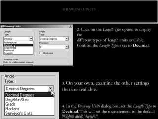
Every object we construct in a CAD system is
measured in units. We should determine the system of
units within the CAD system before creating the first
geometric entities.
1. In the Menu Bar select:
[Format] - [Units]
• The AutoCAD Menu Bar contains multiple pulldown menus,
where all of the AutoCAD commands can be accessed. Note
that many of the menu items listed in the pull-down menus
can also be accessed
through the Quick Access toolbar and/or Ribbonpanels.
H R P R T 0 0 1 @ G M A I L . C O M
7
DRAWING UNITS
2. Click on the Length Type option to display
the
different types of length units available.
Confirm the Length Type is set to Decimal.
3. On your own, examine the other settings
that are available.
4. In the Drawing Units dialog box, set the Length Type to
Decimal. This will set the measurement to the default
English units, inches.H R P R T 0 0 1 @ G M A I L . C O M
8
BASIC DRAWING TOOLS
• LINE
• POLYLINE
• RECTANGLE
• CIRCLE
• SPLINE
• ELLIPSE ARC
• BLOCK
• HATCH
• TEXT
• CONST. LINE
• POLYGON
• ELLIPSE
• POINT
• REGION
H R P R T 0 0 1 @ G M A I L . C O M
9
There are 3 AutoCAD coordinates system you should know. Absolute coordinates, Relative
coordinates and Polar coordinates.
Absolute Coordinates:All input points specify in your drawing using standard Cartesian
coordinates x and y. Using absolute coordinate, points entered by typing x,y [Enter]
Relative Coordinates: After first points entered, your next points can be entered by
specifying the next coordinate compare/relative from the first points. The relative
coordinate started with symbol “@” tell AutoCAD it was a relative coordinates. Using
relative coordinate, points entered by typing @x,y [Enter]
Polar Coordinates: Polar coordinates used when you need to draw the next points at
specify angle. Polar coordinates system in AutoCAD specifies distance length at which
angle. Using polar coordinate, points entered by typing @distance<angle [Enter]
CORDINATE SYSTEMS
H R P R T 0 0 1 @ G M A I L . C O M
10
ABSOLUTE CORDINATE
Enter LINE command: L [Enter]
Start line at point A: 0,0 [Enter]
End first line at point B: 2,2 [Enter]
End of second line at point C: 2,3 [Enter]
H R P R T 0 0 1 @ G M A I L . C O M
11
RELATIVE CORDINATE
Enter LINE command: L [Enter]
Start line at point A: 0,0 [Enter]
End first line at point B: @2,2 [Enter]
End of second line at point C: @0,1 [Enter]
H R P R T 0 0 1 @ G M A I L . C O M
12
POLAR CORDINATE
Enter LINE command: L [Enter]
Start line at point A: 0,0 [Enter]
End first line at point B: @2.828<45 [Enter]
End of second line at point C: @1<90 [Enter]
H R P R T 0 0 1 @ G M A I L . C O M
13
MODIFY
The modify tools (from left to right):
Erase, Copy, Mirror, Offset, Array, Move, Rotate, Scale, Stretch,
Lengthen, Trim, Extend, Break at point, Break, Chamfer, Fillet,
Explode
H R P R T 0 0 1 @ G M A I L . C O M
14
Mirror - The mirror command will create a mirror image of any selected
drawing elements along any line of symmetry specified by the user.
MIRROR
H R P R T 0 0 1 @ G M A I L . C O M
15
Offset will make a copy of a line or series of selected lines by a specified
distance in the direction specified.
OFFSET
H R P R T 0 0 1 @ G M A I L . C O M
16
ARRAY
The array command quickly creates copies of a selected
object(s) to a specified spacing..
H R P R T 0 0 1 @ G M A I L . C O M
17
POLAR ARRAY
H R P R T 0 0 1 @ G M A I L . C O M
18
MOVE : The move command works exactly the same as the copy command
described above, except instead of creating a copy of the selected objects, the
second objects are moved.
SCALE : The scale command scales the size of a selected object(s) by a
defined scale factor from a selected base point. The selected objects can be
scaled up to increase size
LENGTHEN : The lengthen command will lengthen a selected line.
EXTEND :The extend command is similar to the trim command in how it
functions, except it extends a selected line to a point of intersection of
another selected object.
OTHER MODIFY COMMANDS
H R P R T 0 0 1 @ G M A I L . C O M
19
The trim command is an extremely useful tool which will erase all
parts of an object beyond or within its intersection with another
object.
TRIM
H R P R T 0 0 1 @ G M A I L . C O M
20
CHAMFER: The chamfer command will chamfer the intersection of two lines
to a specified distance.
FILLET :The fillet command is very similar to the chamfer command above,
except instead of creating a straight line chamfer, Autocad creates a radius
between the two points.
CHAMFER N FILLET
H R P R T 0 0 1 @ G M A I L . C O M
21
DIMENSIONING:
Bring up the Layer dialog box and make DIM your current layer.This is one
time when I recommend to use the icons. Dimensioning is a LOT easier this
way. If you don't see your dimensioning toolbar on the screen, right click on
one of your toolbar icons and check the Dimension checkbox. You'll see the
toolbar appear. Close the Toolbars dialog box.There are several different types
of dimensions, here are the ones you'll be using in this lesson
LAYERS AND DIMENSIONS
H R P R T 0 0 1 @ G M A I L . C O M
22
COLUMN DESCRIPTION
LINEAR
dimensions are used for dimensioning either
horizontal or vertical distances.
ALIGNED
dimensions will measure the actual length of
an angled line.
RADIUS
dimensions will give you the radius of either
arcs or circles.
DIAMETER dimensions are used on circles.
ANGULAR
dimensions will measure the angle between
two lines that you pick.
BASELINE
dimensions are a special type that will
automatically stack dimensions along one
plane as you pick points. This is only seen
on the Annotate Ribbon with 'Continue'.
TYPES OF DIMENSION
H R P R T 0 0 1 @ G M A I L . C O M
23
Layers: independent drawing spaces that stack on top of each other to create
an overall image. Organizing objects in layers is important when you work on
big projects (Architecture for example). You use layers to organize your project in
such a way that every group of similar things is in their own layers
LAYERS
H R P R T 0 0 1 @ G M A I L . C O M
24
3 D CAD
Types of Solid Models
Wireframe Models Consists of lines, arcs, and curves that define
the object.There are no surfaces. Objects appear as outlines only
Time consuming to make it part
Surface Models:Represent a thin layer or shell of the shape of
an objec tMade up of edges and surfaces Surfaces models are
created by using sweeping, lofting, or revolving 2D lines or arcs
H R P R T 0 0 1 @ G M A I L . C O M
25
Solid Models :Are made up of surfaces and the volume inside Solid models
have properties of mass, volume, center of gravity, and moments-of-inertia
You can easily create 3D primitives such as boxes, cones, cylinders, and
spheres or create 3D models from sweeping, lofting, or extruding 2D closed
objects or profiles.
Mesh Models :Consists of vertices, edges, and faces that use triangles and
quads to define the 3D shape Meshes have to mass properties Meshes allow
greater ability to manipulate and deform surfaces You can covert meshes into
solid models
TYPES
H R P R T 0 0 1 @ G M A I L . C O M
26
•Models can be rotated or viewed from any position
•You can generate section and auxiliary views
•You can remove hidden lines and do realistic shading
•You can run part interference checks for engineering analysis
•You can add lighting and realistic rendering to models
•You can create animations
•You can extract manufacturing data for making the part
ADVANTAGES OF 3D MODEL
H R P R T 0 0 1 @ G M A I L . C O M
27
3D WORKSPACE
To enter 3D workspace go to status
To enter 3D workspace go to
status bar and select “3D
Modeling” from the workspace
switching button
e switching button
H R P R T 0 0 1 @ G M A I L . C O M
28
VIEW AND NAVIGATION
ViewCube
Compass ring- rotate
Faces- standard orthographic view
Corners- ¾ view
Edges- ½ view
3D Orbit (View Menu)
Uses cursor
Camera moves, not the object
To use hold down “Shift
Key” and middle mouse
button together
Steering Wheel
4 different kinds
Can place anywhere on screen
H R P R T 0 0 1 @ G M A I L . C O M
29
VISUAL STYLES
Group of settings that control edges and shading in
the viewport
Opens and docks on left of screen
There are five default styles:
2D Wireframe- NOT use full in 3D
3D Hidden- Hides back faces
3D Wireframe- XYZ planes shaded
Conceptual-Smoothes polygons and uses warm
colors to contrast faces
Realistic- Shades faces and applies any preselected
materials (i.e., brick)
H R P R T 0 0 1 @ G M A I L . C O M
30
CREATING 3D OBJECTS
Extrude Commands A closed polyline
will create a 3D
Solid Model
An open
polyline will
create a surface
model
H R P R T 0 0 1 @ G M A I L . C O M
31
2D LINE TO 3D
NOTE: In order for
2D lines and/or arcs
to be extruded into a
solid 3D model you
must use the “Edit
Polyline Command
(PEDIT)” to
convert the separate
line segments into
one closed polyline.
H R P R T 0 0 1 @ G M A I L . C O M
32
EXTRUDE OPTIONS
Path
Specifies the extrusion
path based on an object
that you select. The path is
moved to the centroid of
the profile. Then the
profile of the selected
object is extruded along
the chosen path to create
solids or surfaces.
The path should not lie on
the same plane as the
object, nor should the
path have areas of high
curvature H R P R T 0 0 1 @ G M A I L . C O M
33
XTRUDE CONICAL
Taper Angle
Sets an angle of taper for an extrusion.
Positive angles taper in from the base object.
Negative angles taper out. The default angle, 0,
extrudes a 2D object perpendicular to its 2D plane.
All selected objects and loops are tapered to the same
value.
Specifying a large taper angle or a long extrusion
height can cause the object or portions of the object
to taper to a point before reaching the extrusion
height.
Individual loops of a region are always extruded to
the same height.
When an arc is part of a tapered extrusion, the angle
of the arc remains constant, and the radius of the arc
changes H R P R T 0 0 1 @ G M A I L . C O M
34
REVOLVE
Revolve Tool
You can revolve closed
objects to create 3D solid
models and open objects to
create surface models.
Objects can be revolved
360 degrees or another
specified angle.
You can revolve more than
one object.
Gap creates
hole
gap
H R P R T 0 0 1 @ G M A I L . C O M
35
LOFT
Loft Tool
Create a 3D solid or surface by lofting
a profile through a set of two or more
cross-section profiles.
The cross-section profiles define the
shape of the resulting solid or surface
object. You must specify at least two
cross-section profiles.
The cross sections that you use when
lofting must be all open or all closed.
You cannot use a selection set that
includes both open and closed curves.
H R P R T 0 0 1 @ G M A I L . C O M
36
SWEEP
Sweep Tool
Create a new solid or surface by
sweeping a planar curve (profile) along
a path.
The SWEEP command draws a solid
or surface object by extending a profile
shape (the swept object) along a
specified path. When you sweep a
profile along a path, the profile is
moved and aligned normal
(perpendicular) to the path.
If you sweep a closed curve along a
path, the result is a solid. If you sweep
an open curve along a path, the result is
a surface.
H R P R T 0 0 1 @ G M A I L . C O M
37
END
H R P R T 0 0 1 @ G M A I L . C O M
38

Auto cad ppt

  • 1.
    Presentation on basicAutocad tools AUTO CAD H R P R T 0 0 1 @ G M A I L . C O M 1
  • 2.
    Auto Cad Introduction BasicDrawing Tools Modify Tools Layers And Dimensions Section Views and Blocks 3d Modelling INDEX H R P R T 0 0 1 @ G M A I L . C O M 2
  • 3.
    AutoCAD is acommercial computer-aided design (CAD) and drafting software application. Developed and marketed by Autodesk, AutoCAD was first released in December 1982 as a desktop app running on microcomputers with internal graphics controllers. Prior to the introduction of AutoCAD, most commercial CAD programs ran on mainframe computers or minicomputers, with each CAD operator (user) working at a separate graphics terminal. Since 2010, AutoCAD was released as a mobile and web app as well, marketed as AutoCAD 360. AutoCAD is used across a wide range of industries, by architects, project managers, engineers, graphic designers, and many other professionals. It was supported by 750 training centers worldwide in 1994. WHAT IS AUTO CAD H R P R T 0 0 1 @ G M A I L . C O M 3
  • 4.
    ONCE THE PROGRAMIS LOADED INTO MEMORY, THE AUTOCAD DRAWING SCREEN WILL APPEAR ON THE SCREEN. AUTOCAD AUTOMATICALLY ASSIGNS GENERIC NAME, DRAWING X, AS NEW DRAWINGS ARE CREATED. IN OUR EXAMPLE, AUTOCAD OPENED THE GRAPHICS WINDOW USING THE DEFAULT SYSTEM UNITS AND ASSIGNED THE DRAWING NAME DRAWING1. H R P R T 0 0 1 @ G M A I L . C O M 4
  • 5.
    THE AUTO CADWINDOW H R P R T 0 0 1 @ G M A I L . C O M 5
  • 6.
    RIBBON BAR The mostprominent feature in the autocad besides the drawing area is the ribbon. This is where user can selectthe tools to draw, edit or perform other functions.The ribbon contains a set of panels representing groups of tools and features. The name of each Ribbon panel is found in its title bar at the bottom of the pannel H R P R T 0 0 1 @ G M A I L . C O M 6
  • 7.
    DRAWING UNITS SETUP Everyobject we construct in a CAD system is measured in units. We should determine the system of units within the CAD system before creating the first geometric entities. 1. In the Menu Bar select: [Format] - [Units] • The AutoCAD Menu Bar contains multiple pulldown menus, where all of the AutoCAD commands can be accessed. Note that many of the menu items listed in the pull-down menus can also be accessed through the Quick Access toolbar and/or Ribbonpanels. H R P R T 0 0 1 @ G M A I L . C O M 7
  • 8.
    DRAWING UNITS 2. Clickon the Length Type option to display the different types of length units available. Confirm the Length Type is set to Decimal. 3. On your own, examine the other settings that are available. 4. In the Drawing Units dialog box, set the Length Type to Decimal. This will set the measurement to the default English units, inches.H R P R T 0 0 1 @ G M A I L . C O M 8
  • 9.
    BASIC DRAWING TOOLS •LINE • POLYLINE • RECTANGLE • CIRCLE • SPLINE • ELLIPSE ARC • BLOCK • HATCH • TEXT • CONST. LINE • POLYGON • ELLIPSE • POINT • REGION H R P R T 0 0 1 @ G M A I L . C O M 9
  • 10.
    There are 3AutoCAD coordinates system you should know. Absolute coordinates, Relative coordinates and Polar coordinates. Absolute Coordinates:All input points specify in your drawing using standard Cartesian coordinates x and y. Using absolute coordinate, points entered by typing x,y [Enter] Relative Coordinates: After first points entered, your next points can be entered by specifying the next coordinate compare/relative from the first points. The relative coordinate started with symbol “@” tell AutoCAD it was a relative coordinates. Using relative coordinate, points entered by typing @x,y [Enter] Polar Coordinates: Polar coordinates used when you need to draw the next points at specify angle. Polar coordinates system in AutoCAD specifies distance length at which angle. Using polar coordinate, points entered by typing @distance<angle [Enter] CORDINATE SYSTEMS H R P R T 0 0 1 @ G M A I L . C O M 10
  • 11.
    ABSOLUTE CORDINATE Enter LINEcommand: L [Enter] Start line at point A: 0,0 [Enter] End first line at point B: 2,2 [Enter] End of second line at point C: 2,3 [Enter] H R P R T 0 0 1 @ G M A I L . C O M 11
  • 12.
    RELATIVE CORDINATE Enter LINEcommand: L [Enter] Start line at point A: 0,0 [Enter] End first line at point B: @2,2 [Enter] End of second line at point C: @0,1 [Enter] H R P R T 0 0 1 @ G M A I L . C O M 12
  • 13.
    POLAR CORDINATE Enter LINEcommand: L [Enter] Start line at point A: 0,0 [Enter] End first line at point B: @2.828<45 [Enter] End of second line at point C: @1<90 [Enter] H R P R T 0 0 1 @ G M A I L . C O M 13
  • 14.
    MODIFY The modify tools(from left to right): Erase, Copy, Mirror, Offset, Array, Move, Rotate, Scale, Stretch, Lengthen, Trim, Extend, Break at point, Break, Chamfer, Fillet, Explode H R P R T 0 0 1 @ G M A I L . C O M 14
  • 15.
    Mirror - Themirror command will create a mirror image of any selected drawing elements along any line of symmetry specified by the user. MIRROR H R P R T 0 0 1 @ G M A I L . C O M 15
  • 16.
    Offset will makea copy of a line or series of selected lines by a specified distance in the direction specified. OFFSET H R P R T 0 0 1 @ G M A I L . C O M 16
  • 17.
    ARRAY The array commandquickly creates copies of a selected object(s) to a specified spacing.. H R P R T 0 0 1 @ G M A I L . C O M 17
  • 18.
    POLAR ARRAY H RP R T 0 0 1 @ G M A I L . C O M 18
  • 19.
    MOVE : Themove command works exactly the same as the copy command described above, except instead of creating a copy of the selected objects, the second objects are moved. SCALE : The scale command scales the size of a selected object(s) by a defined scale factor from a selected base point. The selected objects can be scaled up to increase size LENGTHEN : The lengthen command will lengthen a selected line. EXTEND :The extend command is similar to the trim command in how it functions, except it extends a selected line to a point of intersection of another selected object. OTHER MODIFY COMMANDS H R P R T 0 0 1 @ G M A I L . C O M 19
  • 20.
    The trim commandis an extremely useful tool which will erase all parts of an object beyond or within its intersection with another object. TRIM H R P R T 0 0 1 @ G M A I L . C O M 20
  • 21.
    CHAMFER: The chamfercommand will chamfer the intersection of two lines to a specified distance. FILLET :The fillet command is very similar to the chamfer command above, except instead of creating a straight line chamfer, Autocad creates a radius between the two points. CHAMFER N FILLET H R P R T 0 0 1 @ G M A I L . C O M 21
  • 22.
    DIMENSIONING: Bring up theLayer dialog box and make DIM your current layer.This is one time when I recommend to use the icons. Dimensioning is a LOT easier this way. If you don't see your dimensioning toolbar on the screen, right click on one of your toolbar icons and check the Dimension checkbox. You'll see the toolbar appear. Close the Toolbars dialog box.There are several different types of dimensions, here are the ones you'll be using in this lesson LAYERS AND DIMENSIONS H R P R T 0 0 1 @ G M A I L . C O M 22
  • 23.
    COLUMN DESCRIPTION LINEAR dimensions areused for dimensioning either horizontal or vertical distances. ALIGNED dimensions will measure the actual length of an angled line. RADIUS dimensions will give you the radius of either arcs or circles. DIAMETER dimensions are used on circles. ANGULAR dimensions will measure the angle between two lines that you pick. BASELINE dimensions are a special type that will automatically stack dimensions along one plane as you pick points. This is only seen on the Annotate Ribbon with 'Continue'. TYPES OF DIMENSION H R P R T 0 0 1 @ G M A I L . C O M 23
  • 24.
    Layers: independent drawingspaces that stack on top of each other to create an overall image. Organizing objects in layers is important when you work on big projects (Architecture for example). You use layers to organize your project in such a way that every group of similar things is in their own layers LAYERS H R P R T 0 0 1 @ G M A I L . C O M 24
  • 25.
    3 D CAD Typesof Solid Models Wireframe Models Consists of lines, arcs, and curves that define the object.There are no surfaces. Objects appear as outlines only Time consuming to make it part Surface Models:Represent a thin layer or shell of the shape of an objec tMade up of edges and surfaces Surfaces models are created by using sweeping, lofting, or revolving 2D lines or arcs H R P R T 0 0 1 @ G M A I L . C O M 25
  • 26.
    Solid Models :Aremade up of surfaces and the volume inside Solid models have properties of mass, volume, center of gravity, and moments-of-inertia You can easily create 3D primitives such as boxes, cones, cylinders, and spheres or create 3D models from sweeping, lofting, or extruding 2D closed objects or profiles. Mesh Models :Consists of vertices, edges, and faces that use triangles and quads to define the 3D shape Meshes have to mass properties Meshes allow greater ability to manipulate and deform surfaces You can covert meshes into solid models TYPES H R P R T 0 0 1 @ G M A I L . C O M 26
  • 27.
    •Models can berotated or viewed from any position •You can generate section and auxiliary views •You can remove hidden lines and do realistic shading •You can run part interference checks for engineering analysis •You can add lighting and realistic rendering to models •You can create animations •You can extract manufacturing data for making the part ADVANTAGES OF 3D MODEL H R P R T 0 0 1 @ G M A I L . C O M 27
  • 28.
    3D WORKSPACE To enter3D workspace go to status To enter 3D workspace go to status bar and select “3D Modeling” from the workspace switching button e switching button H R P R T 0 0 1 @ G M A I L . C O M 28
  • 29.
    VIEW AND NAVIGATION ViewCube Compassring- rotate Faces- standard orthographic view Corners- ¾ view Edges- ½ view 3D Orbit (View Menu) Uses cursor Camera moves, not the object To use hold down “Shift Key” and middle mouse button together Steering Wheel 4 different kinds Can place anywhere on screen H R P R T 0 0 1 @ G M A I L . C O M 29
  • 30.
    VISUAL STYLES Group ofsettings that control edges and shading in the viewport Opens and docks on left of screen There are five default styles: 2D Wireframe- NOT use full in 3D 3D Hidden- Hides back faces 3D Wireframe- XYZ planes shaded Conceptual-Smoothes polygons and uses warm colors to contrast faces Realistic- Shades faces and applies any preselected materials (i.e., brick) H R P R T 0 0 1 @ G M A I L . C O M 30
  • 31.
    CREATING 3D OBJECTS ExtrudeCommands A closed polyline will create a 3D Solid Model An open polyline will create a surface model H R P R T 0 0 1 @ G M A I L . C O M 31
  • 32.
    2D LINE TO3D NOTE: In order for 2D lines and/or arcs to be extruded into a solid 3D model you must use the “Edit Polyline Command (PEDIT)” to convert the separate line segments into one closed polyline. H R P R T 0 0 1 @ G M A I L . C O M 32
  • 33.
    EXTRUDE OPTIONS Path Specifies theextrusion path based on an object that you select. The path is moved to the centroid of the profile. Then the profile of the selected object is extruded along the chosen path to create solids or surfaces. The path should not lie on the same plane as the object, nor should the path have areas of high curvature H R P R T 0 0 1 @ G M A I L . C O M 33
  • 34.
    XTRUDE CONICAL Taper Angle Setsan angle of taper for an extrusion. Positive angles taper in from the base object. Negative angles taper out. The default angle, 0, extrudes a 2D object perpendicular to its 2D plane. All selected objects and loops are tapered to the same value. Specifying a large taper angle or a long extrusion height can cause the object or portions of the object to taper to a point before reaching the extrusion height. Individual loops of a region are always extruded to the same height. When an arc is part of a tapered extrusion, the angle of the arc remains constant, and the radius of the arc changes H R P R T 0 0 1 @ G M A I L . C O M 34
  • 35.
    REVOLVE Revolve Tool You canrevolve closed objects to create 3D solid models and open objects to create surface models. Objects can be revolved 360 degrees or another specified angle. You can revolve more than one object. Gap creates hole gap H R P R T 0 0 1 @ G M A I L . C O M 35
  • 36.
    LOFT Loft Tool Create a3D solid or surface by lofting a profile through a set of two or more cross-section profiles. The cross-section profiles define the shape of the resulting solid or surface object. You must specify at least two cross-section profiles. The cross sections that you use when lofting must be all open or all closed. You cannot use a selection set that includes both open and closed curves. H R P R T 0 0 1 @ G M A I L . C O M 36
  • 37.
    SWEEP Sweep Tool Create anew solid or surface by sweeping a planar curve (profile) along a path. The SWEEP command draws a solid or surface object by extending a profile shape (the swept object) along a specified path. When you sweep a profile along a path, the profile is moved and aligned normal (perpendicular) to the path. If you sweep a closed curve along a path, the result is a solid. If you sweep an open curve along a path, the result is a surface. H R P R T 0 0 1 @ G M A I L . C O M 37
  • 38.
    END H R PR T 0 0 1 @ G M A I L . C O M 38