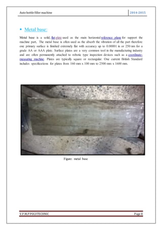
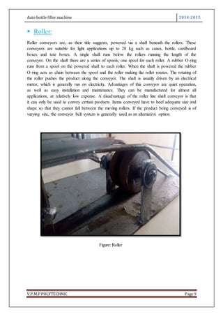
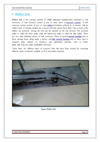
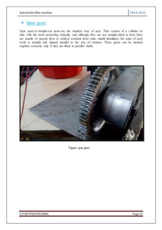
Download to read offline


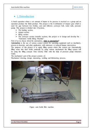
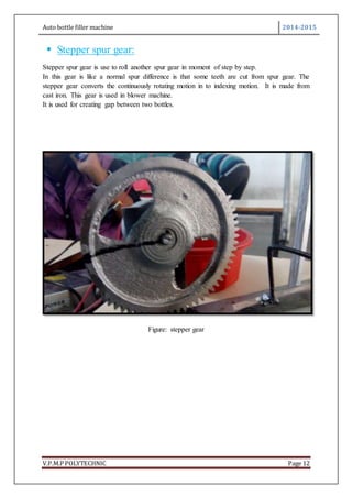
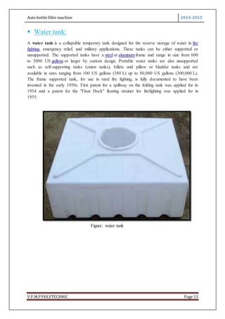
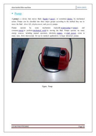
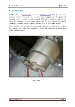


This document describes the design of an automatic bottle filling machine. It consists of four main sections: the loading section, stepper section, filling section, and conveyor section. The key components are a metal base, rollers, rubber belt, spur gears, stepper gear, water tank, pressure pump, and AC/DC motor. The stepper gear is used to create gaps between bottles on the conveyor belt. The pressure pump fills bottles with water from the water tank. The overall purpose is to automatically fill bottles with a set volume of water using various mechanisms to reduce human labor.