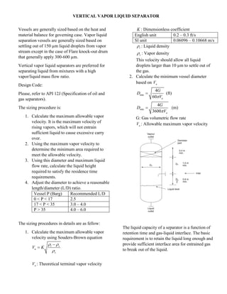
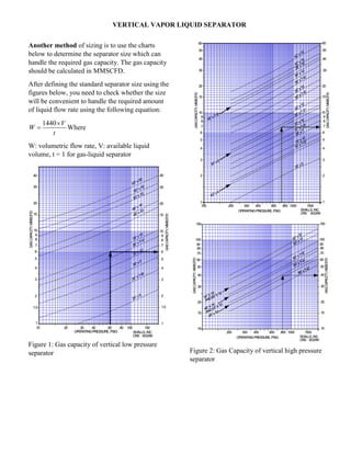
VERTICAL VAPOR LIQUID SEPARATOR
Vessels are generally sized based on the heat and
material balance for governing case. Vapor liquid
separation vessels are generally sized based on
settling out of 150 µm liquid droplets from vapor
stream except in the case of Flare knock-out drum
that generally apply 300-600 µm.
Vertical vapor liquid separators are preferred for
separating liquid from mixtures with a high
vapor/liquid mass flow ratio.
Design Code:
Please, refer to API 12J (Specification of oil and
gas separators).
The sizing procedure is:
1. Calculate the maximum allowable vapor
velocity. It is the maximum velocity of
rising vapors, which will not entrain
sufficient liquid to cause excessive carry
over.
2. Using the maximum vapor velocity to
determine the minimum area required to
meet the allowable velocity.
3. Using this diameter and maximum liquid
flow rate, calculate the liquid height
required to satisfy the residence time
requirements.
4. Adjust the diameter to achieve a reasonable
length/diameter (L/D) ratio.
Vessel P (Barg) Recommended L/D
0 < P < 17 2.5
17 < P < 35 3.0 – 4.0
P > 35 4.0 – 6.0
The sizing procedures in details are as fellow:
1. Calculate the maximum allowable vapor
velocity using Souders-Brown equation
l v
a
v
V K
 



aV : Theoretical terminal vapor velocity
K : Dimensionless coefficient
English unit 0.2 – 0.3 ft/s
SI unit 0.06096 – 0.10668 m/s
l : Liquid density
v : Vapor density
This velocity should allow all liquid
droplets larger than 10 µm to settle out of
the gas.
2. Calculate the minimum vessel diameter
based on aV
min
4
60 a
G
D
V
 (ft)
min
4
3600 a
G
D
V
 (m)
G: Gas volumetric flow rate
aV : Allowable maximum vapor velocity
The liquid capacity of a separator is a function of
retention time and gas-liquid interface. The basic
requirement is to retain the liquid long enough and
provide sufficient interface area for entrained gas
to break out of the liquid.
VERTICAL VAPOR LIQUID SEPARATOR
Another method of sizing is to use the charts
below to determine the separator size which can
handle the required gas capacity. The gas capacity
should be calculated in MMSCFD.
After defining the standard separator size using the
figures below, you need to check whether the size
will be convenient to handle the required amount
of liquid flow rate using the following equation:
1440 V
W
t

 Where
W: volumetric flow rate, V: available liquid
volume, t = 1 for gas-liquid separator
Figure 1: Gas capacity of vertical low pressure
separator Figure 2: Gas Capacity of vertical high pressure
separator

Vertical vapor liquid separator

  • 1.
    VERTICAL VAPOR LIQUIDSEPARATOR Vessels are generally sized based on the heat and material balance for governing case. Vapor liquid separation vessels are generally sized based on settling out of 150 µm liquid droplets from vapor stream except in the case of Flare knock-out drum that generally apply 300-600 µm. Vertical vapor liquid separators are preferred for separating liquid from mixtures with a high vapor/liquid mass flow ratio. Design Code: Please, refer to API 12J (Specification of oil and gas separators). The sizing procedure is: 1. Calculate the maximum allowable vapor velocity. It is the maximum velocity of rising vapors, which will not entrain sufficient liquid to cause excessive carry over. 2. Using the maximum vapor velocity to determine the minimum area required to meet the allowable velocity. 3. Using this diameter and maximum liquid flow rate, calculate the liquid height required to satisfy the residence time requirements. 4. Adjust the diameter to achieve a reasonable length/diameter (L/D) ratio. Vessel P (Barg) Recommended L/D 0 < P < 17 2.5 17 < P < 35 3.0 – 4.0 P > 35 4.0 – 6.0 The sizing procedures in details are as fellow: 1. Calculate the maximum allowable vapor velocity using Souders-Brown equation l v a v V K      aV : Theoretical terminal vapor velocity K : Dimensionless coefficient English unit 0.2 – 0.3 ft/s SI unit 0.06096 – 0.10668 m/s l : Liquid density v : Vapor density This velocity should allow all liquid droplets larger than 10 µm to settle out of the gas. 2. Calculate the minimum vessel diameter based on aV min 4 60 a G D V  (ft) min 4 3600 a G D V  (m) G: Gas volumetric flow rate aV : Allowable maximum vapor velocity The liquid capacity of a separator is a function of retention time and gas-liquid interface. The basic requirement is to retain the liquid long enough and provide sufficient interface area for entrained gas to break out of the liquid.
  • 2.
    VERTICAL VAPOR LIQUIDSEPARATOR Another method of sizing is to use the charts below to determine the separator size which can handle the required gas capacity. The gas capacity should be calculated in MMSCFD. After defining the standard separator size using the figures below, you need to check whether the size will be convenient to handle the required amount of liquid flow rate using the following equation: 1440 V W t   Where W: volumetric flow rate, V: available liquid volume, t = 1 for gas-liquid separator Figure 1: Gas capacity of vertical low pressure separator Figure 2: Gas Capacity of vertical high pressure separator