Downloaded 610 times

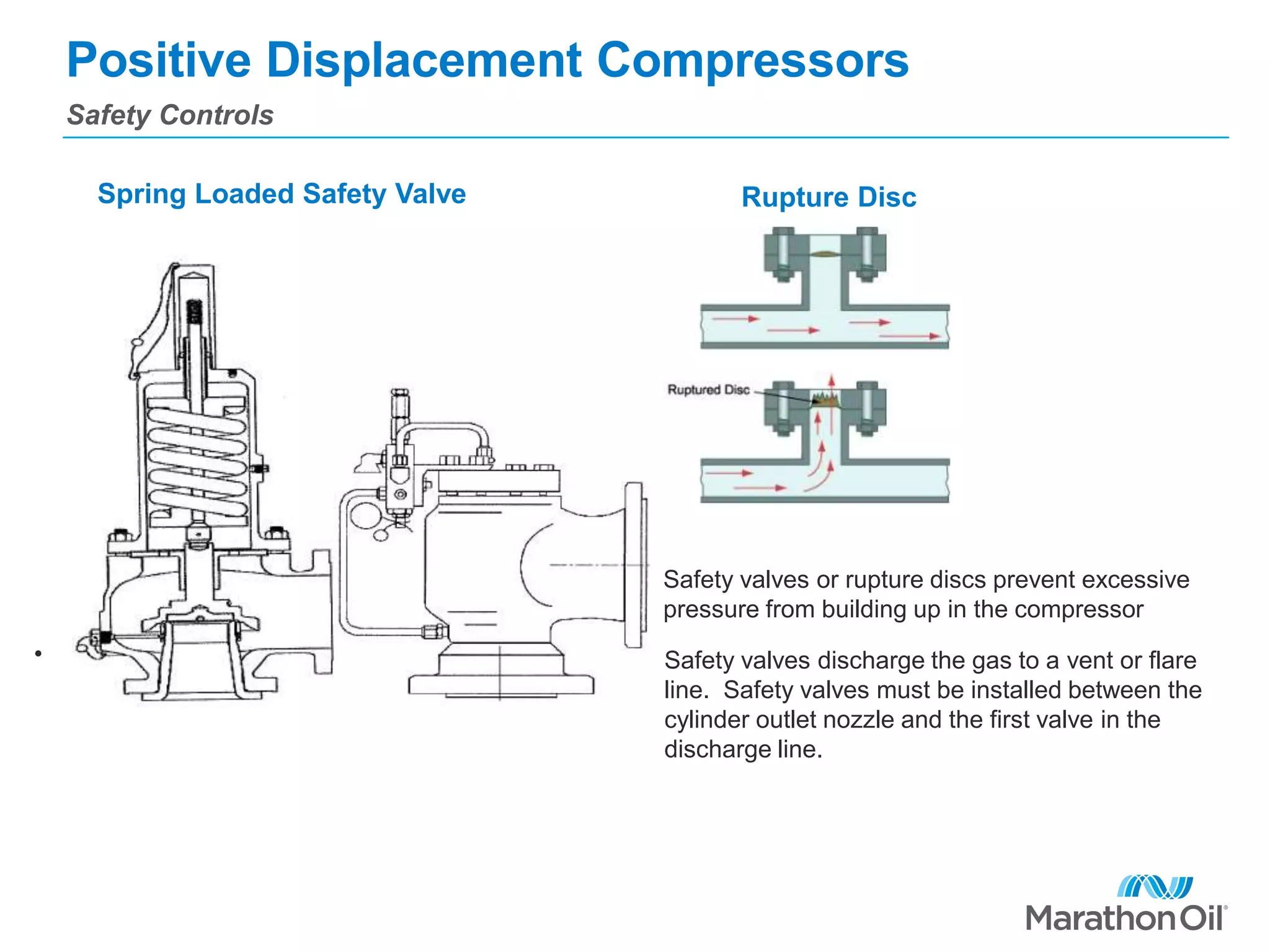
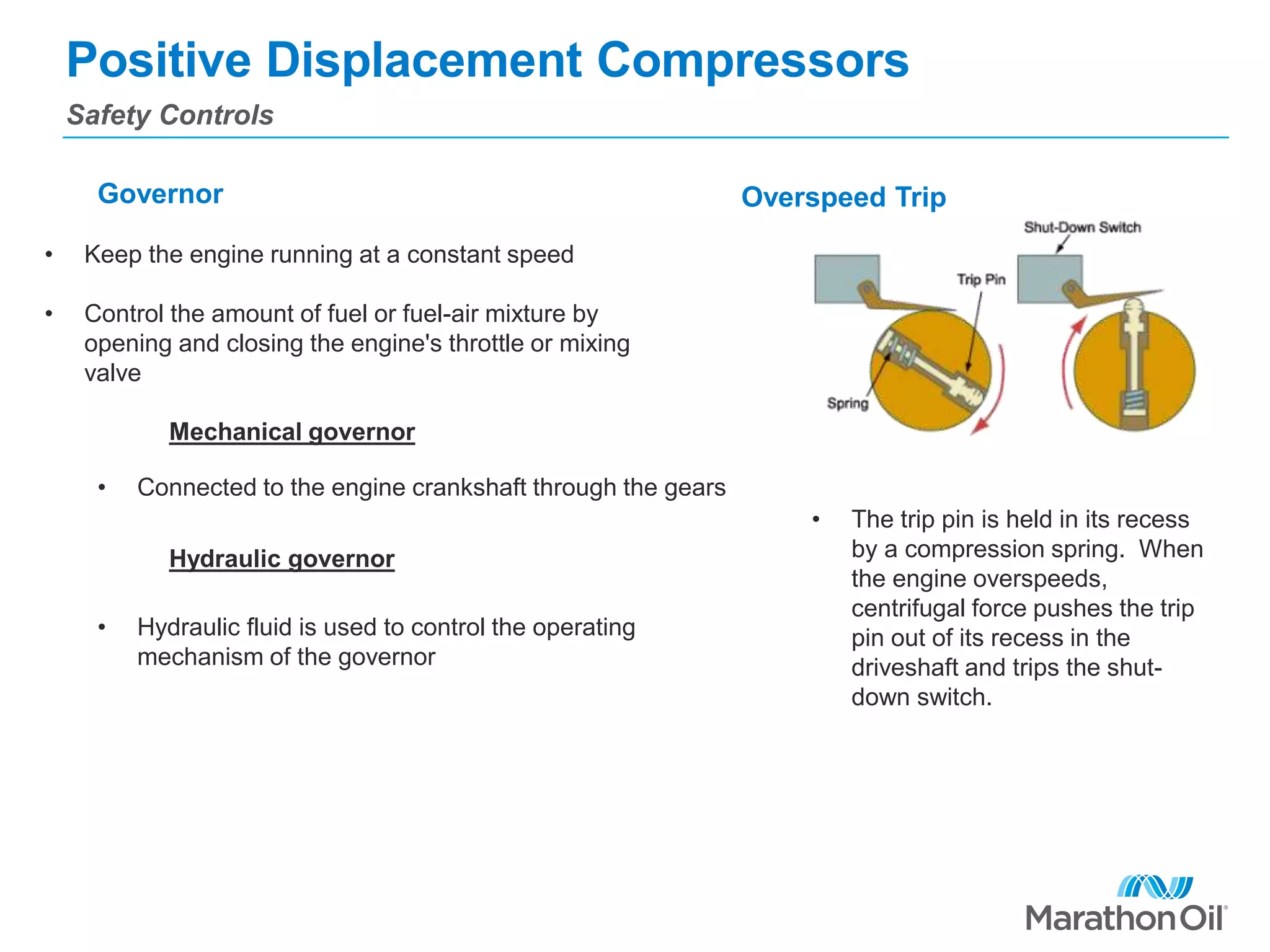
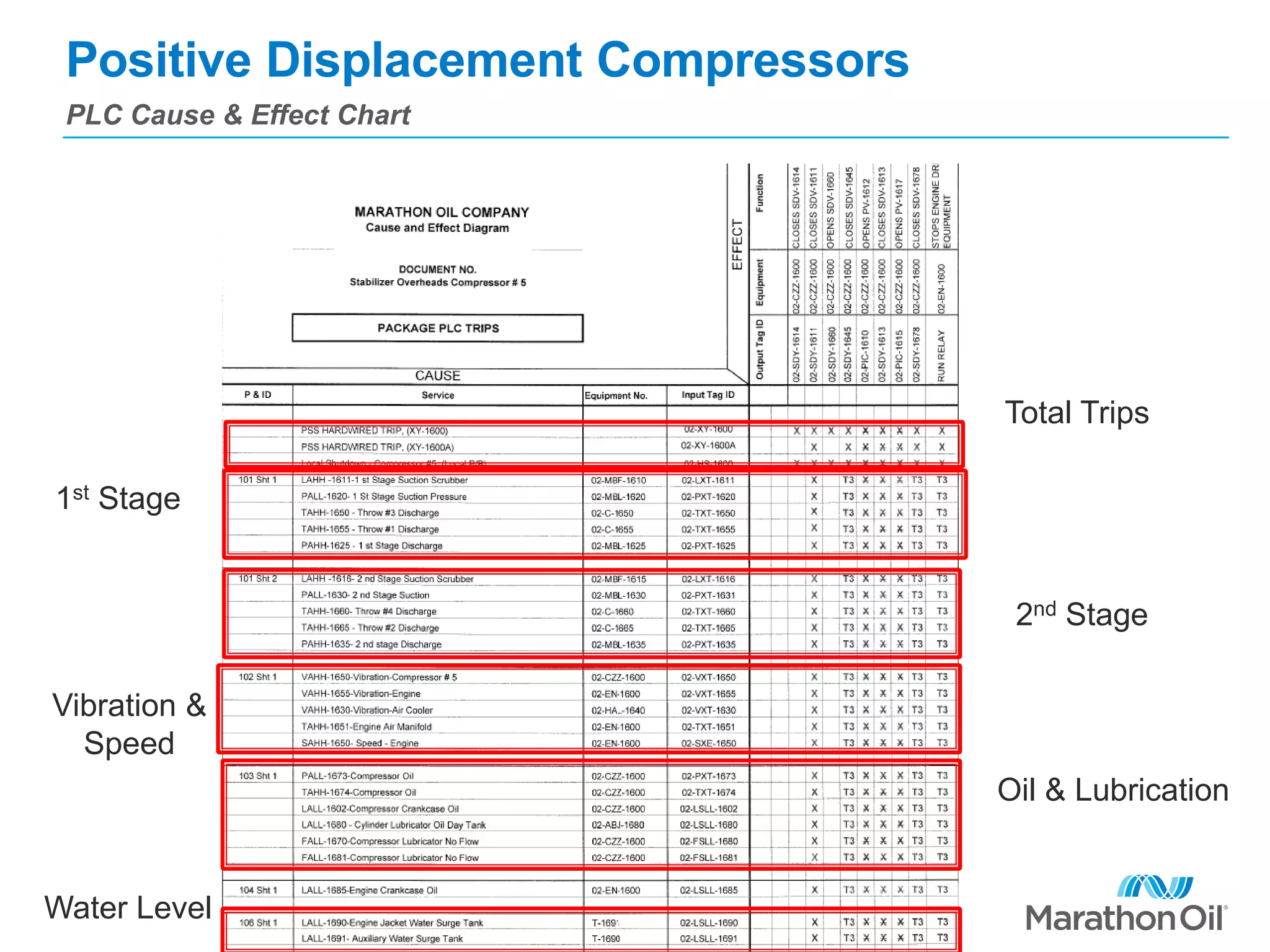


This document is a comprehensive guide on positive displacement compressors, detailing the operational principles, components, and maintenance procedures for both reciprocating and rotary compressors. It covers aspects such as lubrication systems, safety controls, and start-up and shutdown procedures, emphasizing the importance of each part's function in efficient operation. The information aims to help operators understand compressor control and maintenance to ensure safety and reliability in their operation.


