Downloaded 381 times
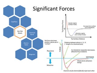
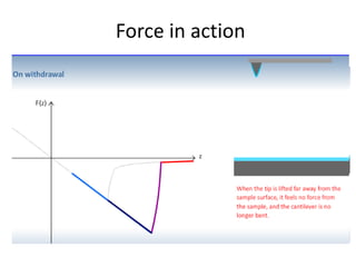
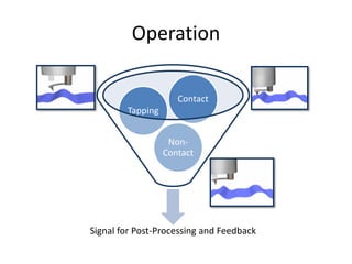
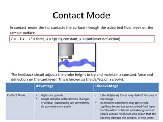
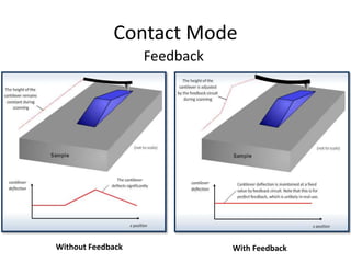
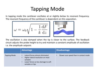
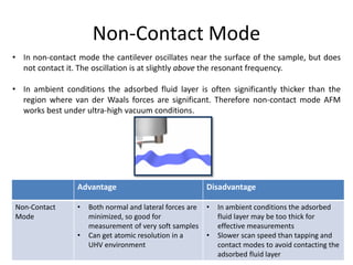
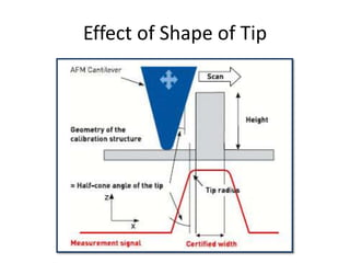
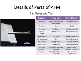
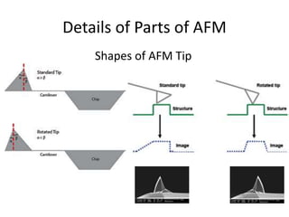
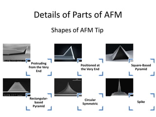
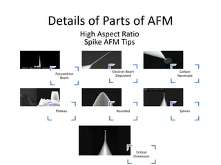
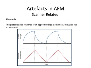
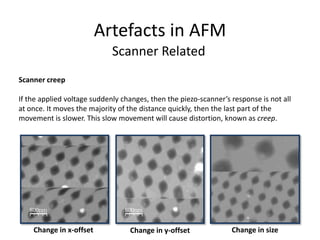
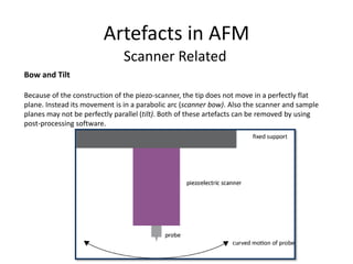
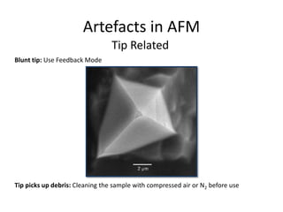
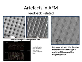
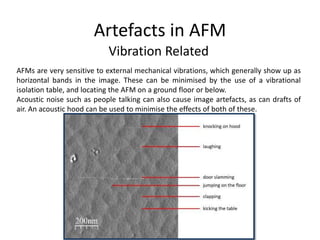
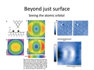
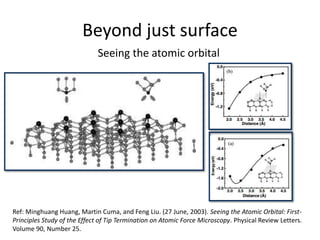


The document provides an overview of atomic force microscopy (AFM), detailing its principles, operational modes (contact, tapping, and non-contact), and advantages and disadvantages of each mode. It also discusses the design aspects of AFM tips and scanners, and addresses common artifacts associated with AFM measurements. Additionally, it briefly mentions advancements in AFM applications, including imaging chemical reactions at the atomic level.