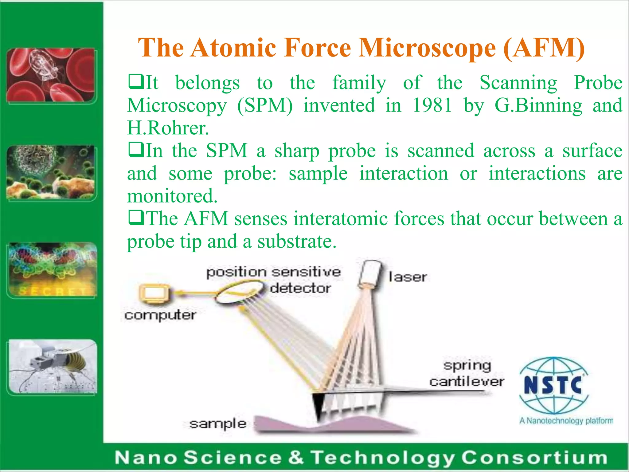
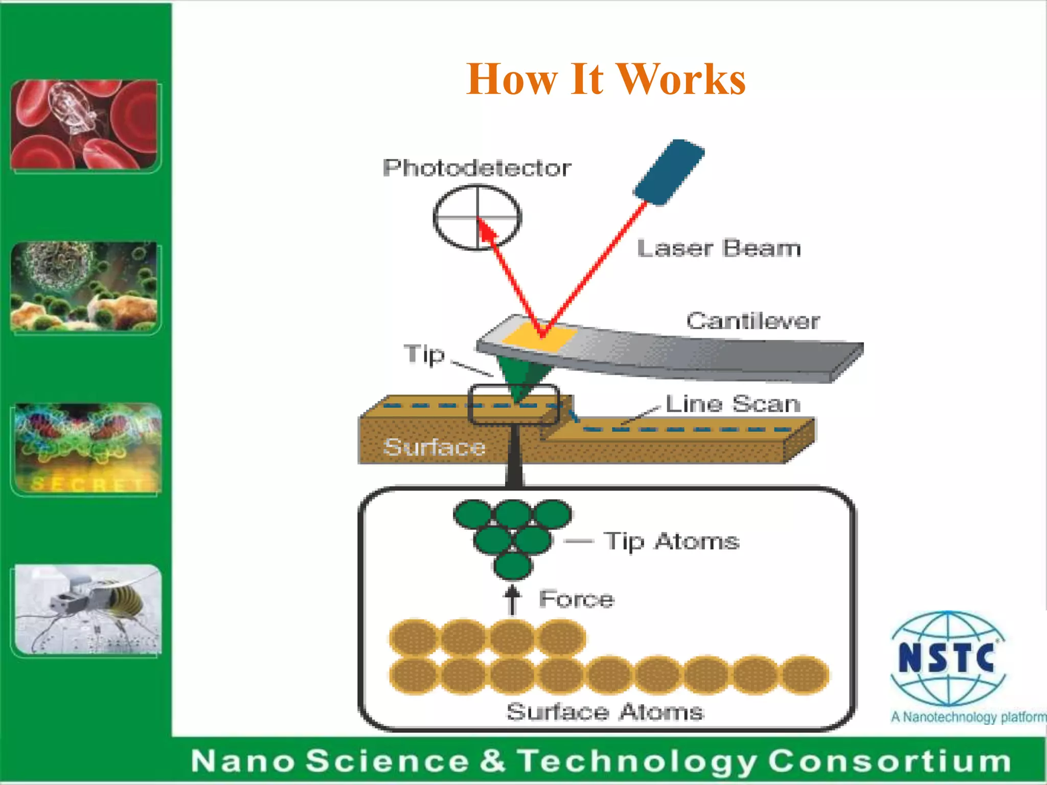
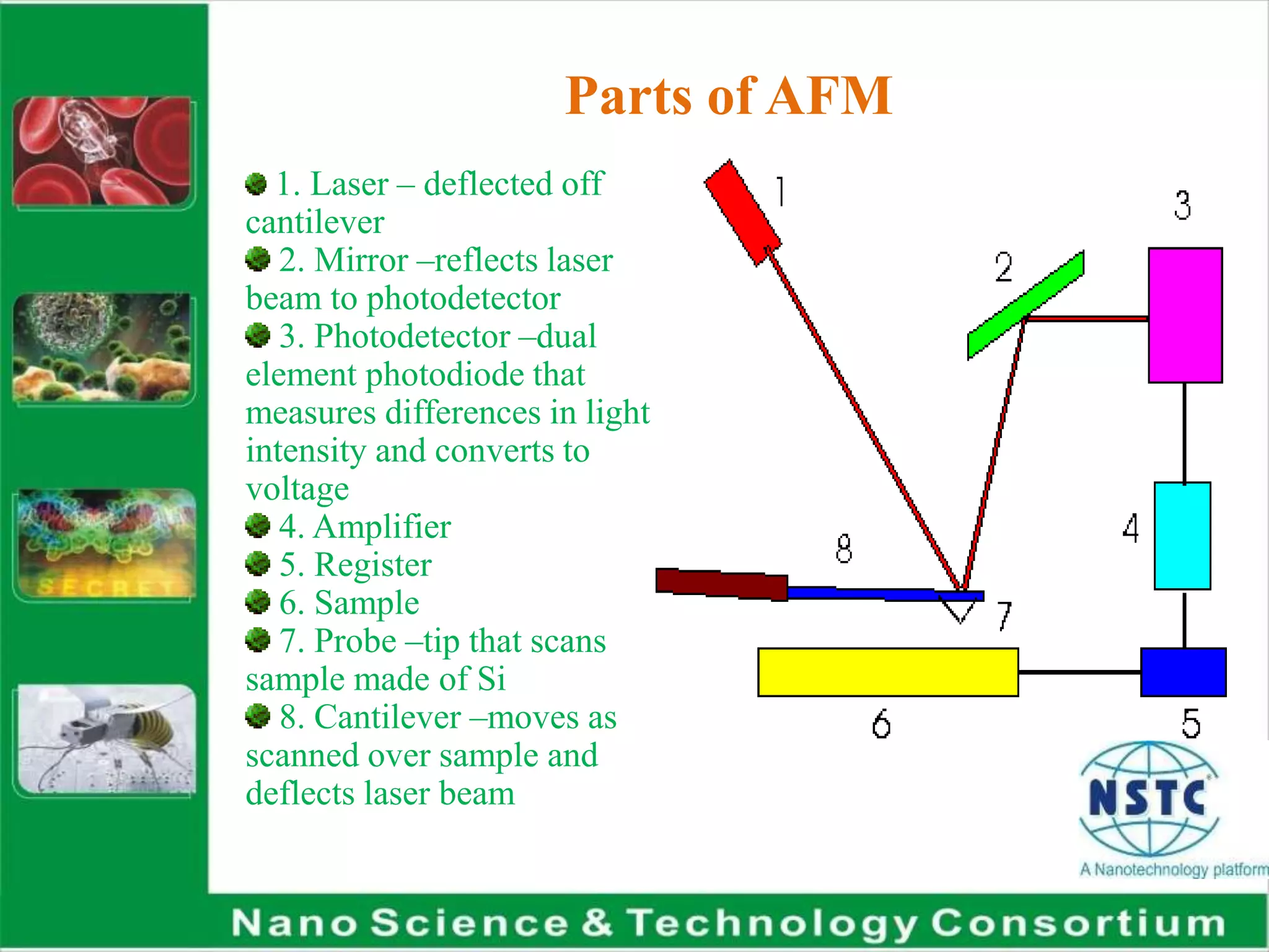
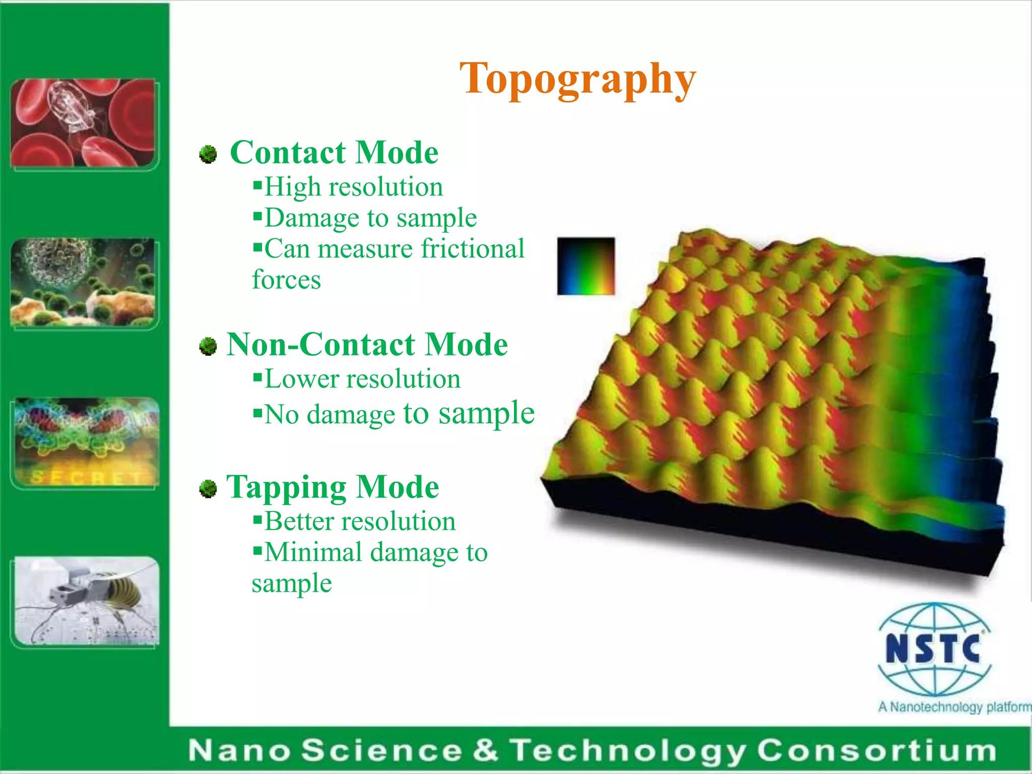
Atomic force
microscopy
The Atomic Force Microscope (AFM)
It belongs to the family of the Scanning Probe
Microscopy (SPM) invented in 1981 by G.Binning and
H.Rohrer.
In the SPM a sharp probe is scanned across a surface
and some probe: sample interaction or interactions are
monitored.
The AFM senses interatomic forces that occur between a
probe tip and a substrate.
History of AFM
1st AFM made by Gerd Binnig and Cristoph
Gerber in 1985
Constructed by gluing tiny shard of
diamond onto one end of tiny strip of gold foil
Small hook at end of the tip pressed against
sample surface
Sample scanned by tracking deflection of
cantilever by monitoring tunneling current to
2nd tip position above cantilever
Developed in order to examine insulating
surfaces
The first AFM
G. Binnig, Ch. Gerber and C.F. Quate, Phys.
Rev. Lett. 56, 930 (1986)
Advantages of using the AFM
Unlike other techniques, AFM can use samples with
just minor preparation, over a large range of
temperatures and in repetitive studies.
The high resolution allows topographical imaging
of samples such as DNA molecules, protein
adsorption or crystal growth, and living cells adsorbed
on biomaterials, etc.
In addition to topographical measurements, AFM is
also capable of complementary techniques that
provide information on other surface properties, e.g.
stiffness, hardness, friction, or elasticity.
It can be also used as a tool for controlled
mechanical nano-stimulation and manipulation
How It Works
Parts of AFM
1. Laser – deflected off
cantilever
2. Mirror –reflects laser
beam to photodetector
3. Photodetector –dual
element photodiode that
measures differences in light
intensity and converts to
voltage
4. Amplifier
5. Register
6. Sample
7. Probe –tip that scans
sample made of Si
8. Cantilever –moves as
scanned over sample and
deflects laser beam
Topography
Contact Mode
High resolution
Damage to sample
Can measure frictional
forces
Non-Contact Mode
Lower resolution
No damage to sample
Tapping Mode
Better resolution
Minimal damage to
sample
Contact Mode
 Measures repulsion between tip and sample
 Force of tip against sample remains constant
 Feedback regulation keeps cantilever deflection
constant
 Voltage required indicates height of sample
 Problems: excessive tracking forces applied by
probe to sample
Non-Contact Mode
 Measures attractive forces between tip and sample
Tip doesn’t touch sample
Van der Waals forces between tip and sample
detected
Problems: Can’t use with samples in fluid
Used to analyze semiconductors
Doesn’t degrade or interfere with sample- better for
soft samples
Tapping (Intermittent-Contact) Mode
 Tip vertically oscillates between contacting sample
surface and lifting of at frequency of 50,000 to
500,000 cycles/sec.
Oscillation amplitude reduced as probe contacts
surface due to loss of energy caused by tip contacting
surface
Advantages: overcomes problems associated with
friction, adhesion, electrostatic forces
More effective for larger scan sizes
Applications
 Study Unfolding Of Proteins
Imagining Of Biomolecules
Force Measurements In Real Solvent Environments
Antibody-Antigen Binding Studies
Ligand-Receptor Binding Studies
Binding Forces Of Complimentary DNA Strands
Study Surface Frictional Forces
Ion Channel Localization
Biological-Applications
 Used to analyze DNA, RNA, protein-nucleic acid
complexes, chromosomes, cell membranes, proteins
and peptides, molecular crystals, polymers,
biomaterials, ligand-receptor binding
Nanometer resolved images of nucleic acids
Imaging of cells
Quantification of molecular interactions in
biological systems
Quantification of electrical surface charge

Atomic force microscopy

  • 1.
  • 2.
    The Atomic ForceMicroscope (AFM) It belongs to the family of the Scanning Probe Microscopy (SPM) invented in 1981 by G.Binning and H.Rohrer. In the SPM a sharp probe is scanned across a surface and some probe: sample interaction or interactions are monitored. The AFM senses interatomic forces that occur between a probe tip and a substrate.
  • 3.
    History of AFM 1stAFM made by Gerd Binnig and Cristoph Gerber in 1985 Constructed by gluing tiny shard of diamond onto one end of tiny strip of gold foil Small hook at end of the tip pressed against sample surface Sample scanned by tracking deflection of cantilever by monitoring tunneling current to 2nd tip position above cantilever Developed in order to examine insulating surfaces
  • 4.
    The first AFM G.Binnig, Ch. Gerber and C.F. Quate, Phys. Rev. Lett. 56, 930 (1986)
  • 5.
    Advantages of usingthe AFM Unlike other techniques, AFM can use samples with just minor preparation, over a large range of temperatures and in repetitive studies. The high resolution allows topographical imaging of samples such as DNA molecules, protein adsorption or crystal growth, and living cells adsorbed on biomaterials, etc. In addition to topographical measurements, AFM is also capable of complementary techniques that provide information on other surface properties, e.g. stiffness, hardness, friction, or elasticity. It can be also used as a tool for controlled mechanical nano-stimulation and manipulation
  • 6.
  • 7.
    Parts of AFM 1.Laser – deflected off cantilever 2. Mirror –reflects laser beam to photodetector 3. Photodetector –dual element photodiode that measures differences in light intensity and converts to voltage 4. Amplifier 5. Register 6. Sample 7. Probe –tip that scans sample made of Si 8. Cantilever –moves as scanned over sample and deflects laser beam
  • 8.
    Topography Contact Mode High resolution Damageto sample Can measure frictional forces Non-Contact Mode Lower resolution No damage to sample Tapping Mode Better resolution Minimal damage to sample
  • 9.
    Contact Mode  Measuresrepulsion between tip and sample  Force of tip against sample remains constant  Feedback regulation keeps cantilever deflection constant  Voltage required indicates height of sample  Problems: excessive tracking forces applied by probe to sample
  • 10.
    Non-Contact Mode  Measuresattractive forces between tip and sample Tip doesn’t touch sample Van der Waals forces between tip and sample detected Problems: Can’t use with samples in fluid Used to analyze semiconductors Doesn’t degrade or interfere with sample- better for soft samples
  • 11.
    Tapping (Intermittent-Contact) Mode Tip vertically oscillates between contacting sample surface and lifting of at frequency of 50,000 to 500,000 cycles/sec. Oscillation amplitude reduced as probe contacts surface due to loss of energy caused by tip contacting surface Advantages: overcomes problems associated with friction, adhesion, electrostatic forces More effective for larger scan sizes
  • 12.
    Applications  Study UnfoldingOf Proteins Imagining Of Biomolecules Force Measurements In Real Solvent Environments Antibody-Antigen Binding Studies Ligand-Receptor Binding Studies Binding Forces Of Complimentary DNA Strands Study Surface Frictional Forces Ion Channel Localization
  • 13.
    Biological-Applications  Used toanalyze DNA, RNA, protein-nucleic acid complexes, chromosomes, cell membranes, proteins and peptides, molecular crystals, polymers, biomaterials, ligand-receptor binding Nanometer resolved images of nucleic acids Imaging of cells Quantification of molecular interactions in biological systems Quantification of electrical surface charge