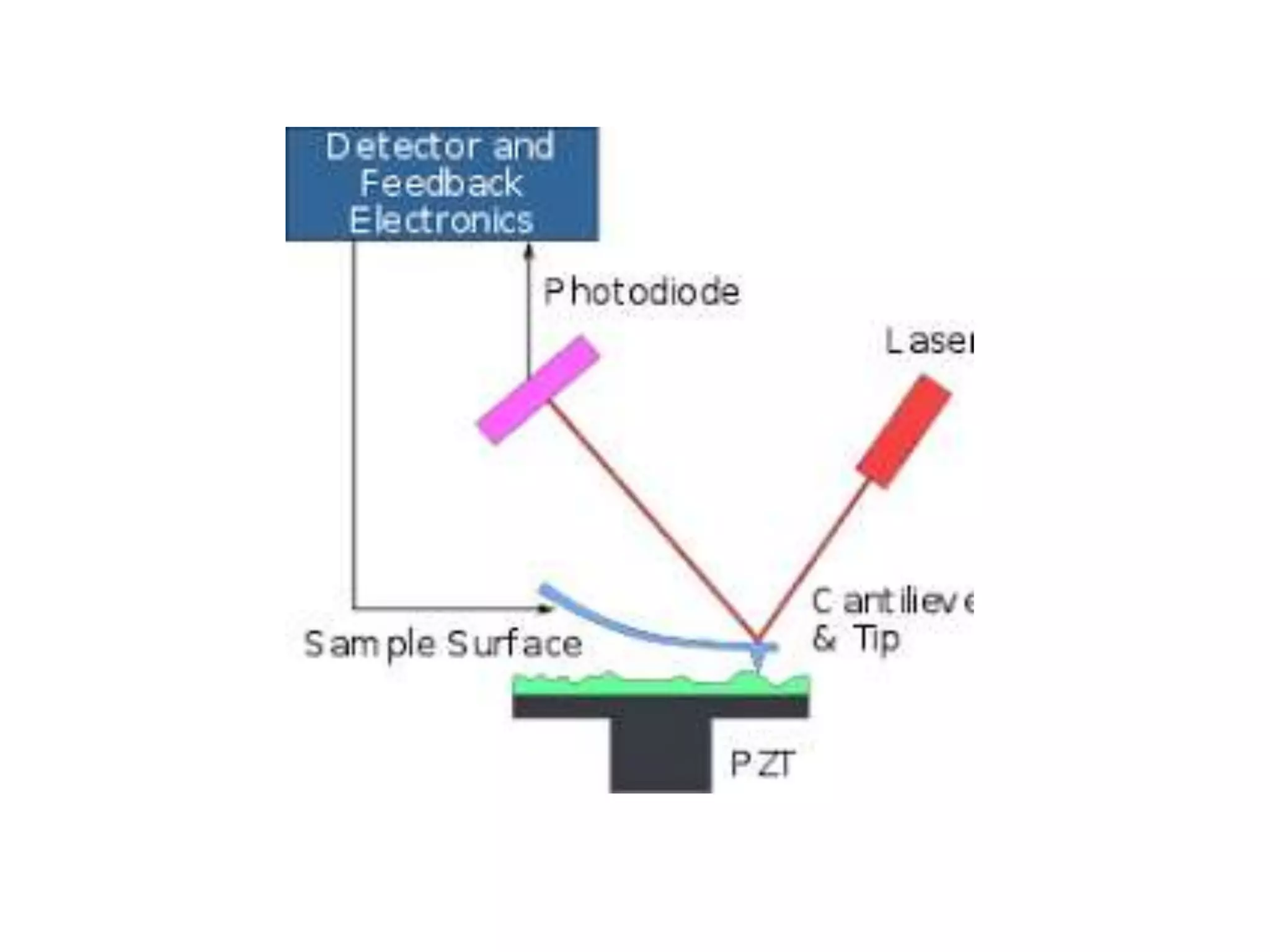
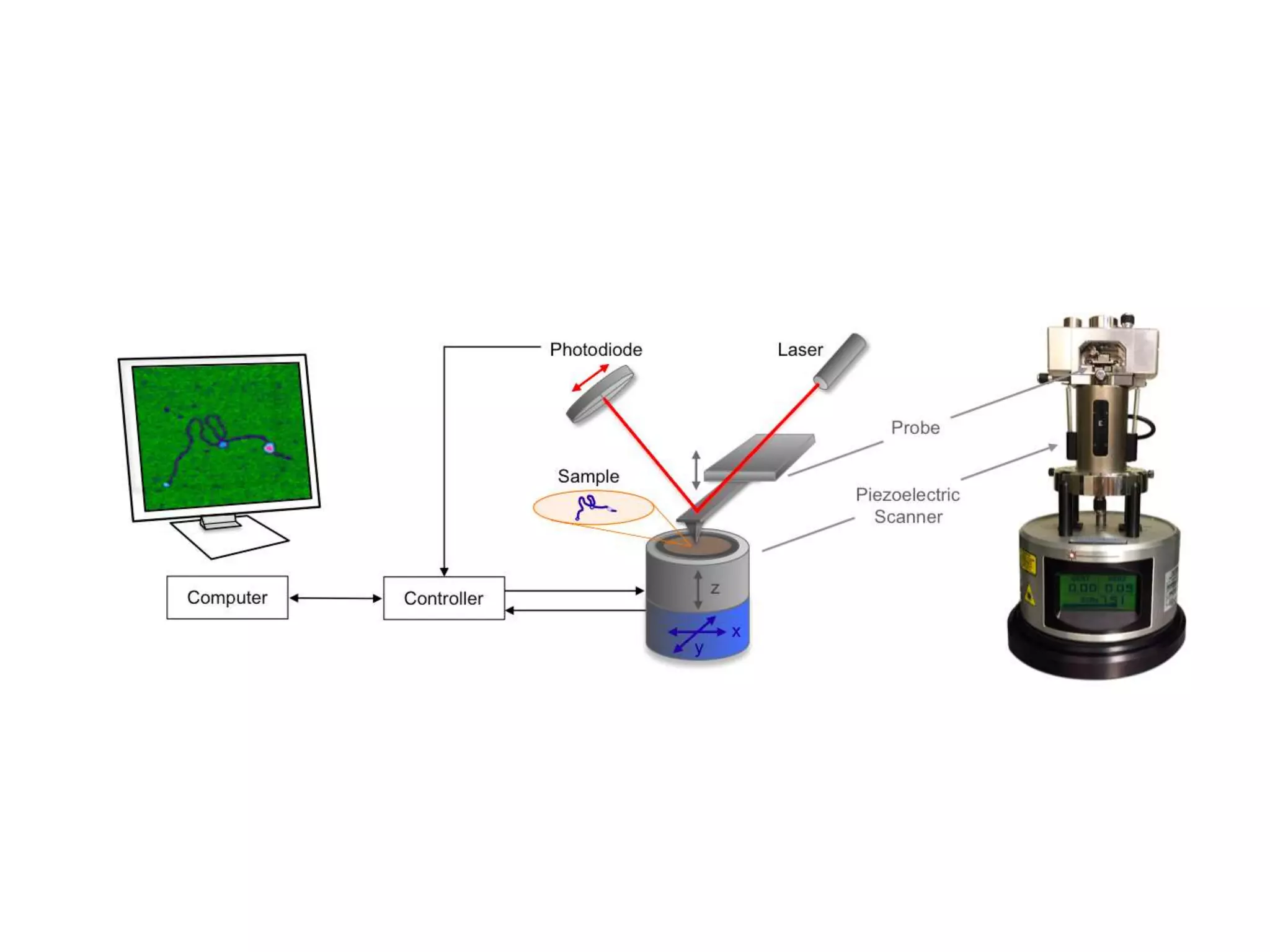
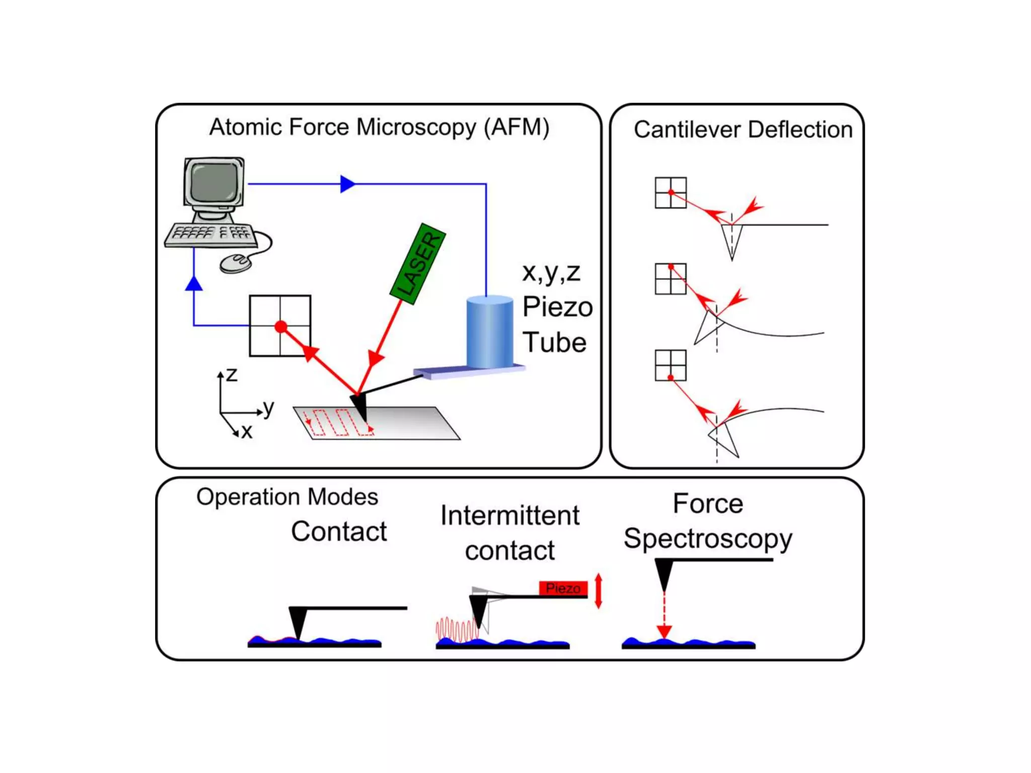
ATOMIC FORCEMICROSCOPE
Dr.K. SENTHILARASAN
ASSISTANT PROFESSOR
EDAYATHANGUDY G.S.PILLAY ARTS &
SCIENCE COLLEGE, NAGAPATTINAM
Atomic force microscopy (AFM) is one of the excellent tools to study the
morphological and textural characteristics like roughness , waviness, lay and flaws of
diverse surfaces .
(a particular form, shape, or structure.)
(appearance, or consistency of a surface or a substance.)
atomic force microscopic analysis is ideal for quantitatively measuring the
three dimensional topography of a sample surface along with the physical properties
like elasticity, adhesion, hardness and friction.
(Topography is the study of the shape and features of land surfaces.)
ATOMIC FORCE MICROSCOPY (AFM)
 An AFM is an mechanical imaging instrument that measures the force
acting between a sharp tip and the surface of a sample.
 When the tip is attached at the free end of a cantilever is scanned across
the surface , the attractive or repulsive force acting between the tip and the
surface will cause a positive or negative deflection of the cantilever .
 These deflections are used to generate a map of the surface topography.
BASIC PRINCIPLE
 Tip
 Cantilever
 Scanner
 Feedback
controller
 A photo detector
 It is generally made up of silicon or silicon nitrate typically pyramidal in
shape.
 It is approximately 100 to 200 microns long.
 0.3 to 2 microns thick and 10 to 40 microns width.
 The end of the tip is often slightly rounded being around ten nanometers in
radius.
 As the tip is very sharp and thin , it can penetrate all the nooks and cracks of
the sample .
TIP
The cantilever needs to be very thin and flexible but strong enough to hold
the tips securely on its end.
THE CANTILEVER
The piezo – electric scanner controls the movement of the tip in the
x, y, and z-directions which is the order of a fraction of a nanometer.
Such accurate movements of the tip could not be possible using
traditional mechanical methods.
For typical AFM scanners , the maximum rangers are 80 mm x 80 mm
the x-y plane and 5mm in the z-directions .
THE SCANNER
FEEDBACK CONTROL
 AFM can be operated with or without feedback control.
 When the electronic feedback is on , as the tip is raster-scanned
across the surface , the scanner will adjust the separation between the tip
and the sample so that a constant deflection is maintained.
 Thus, the deflection of the cantilever reflects the topography of a
sample.
 The planto detector is divided into four parts viz.
A, B, C, and D.
when the laser light is displaced vertically along the position top (A-B)
and the bottom (C-D), there exists a bending due to topography while,
 if this movement is horizontal ( between left and right ), it produces a torsion
due to “friction” ( lateral force ).
 The scanning area is less than 100 nm and the scanning time can be
varied in the range of a fraction of a second to few minutes depending on the
size of the scan and the height of the topographic features on a surface .
 magnifications of the AFM may be between 100 X and 100,000,000 X in
the horizontal (x-y) and the vertical axis.
DETECTOR
 A cantilever with a sharp tip is scanned across the surface of the specimen as
shown in Fig 7.6 .
 the short range or long range forces between the tip of the cantilever and the
specimen surface cause the deflection of the cantilever according to the Hooke’s
law.
 This deflection of the cantilever is measured using the change in the reflection
angle of the laser spot incident of the top surface of the cantilever which behaves
like a mirror.
 This reflected laser light is collected by a position sensitive detector to generate a
map of the surface topography.
WORKING DETAILS
There are three main operational modes
(1) contact AFM ( probe-surface separation is < 0.5 nm )
(2) intermittent contact/tapping mode AFM ( probe-surface separation is 0.5 nm )
(3) Non-contact AFM ( probe-surface separation range is 0.1 – 10 nm )
 The cantilever used for contact mode have force constants typically less than
1n/m and are fabricated from si and siN.
 In contact mode, the sharp tip is brought in close contact with the surface of
the sample (Fig 7.7 ).
 The strong repulsive force appears between the tip and the sample due to the
exchange interactions causes the cantilever to bend in accordance with the
Hooke’s law.
 There are two types contact scanning modes viz.
(I) Constant force
(II) constant height .
CONTACT MODE
CONSTANT FORCE
 To prevent the cantilever tip from damaging the surface of the sample, it
is maintained at a constant angular deflection so that the force applied by
the tip on the surface is also kept constant.
 This is achieved using a feedback mechanism that adjusts the distance
between the tip and the surface to keep the applied force constant and
the motion of the scanner in z-direction is recorded. By using contact-
mode AFM, even “atomic resolution” images can be obtained.
 This constant force mode is generally preferred for most of the
applications.
CONSTANT HEIGHT
 In this mode, the spatial variation of the cantilever deflection is used to
generate the topography image, as the height of the scanner is fixed during
the scanning.
 Constant-height mode is ideal for recording real-time images of changing
surfaces where high scan speed is essential.
 This mode is widely used for studying fluid layers.
 Non-contact cantilevers are fabricated from si and have force constants greater
than 10N/m. in this mode, as the probe has high spring constant than the surface,
it does not stick to the sample surface at small amplitudes, but it oscillates above
the adsorbed fluid layer on the surface during scanning (Fig 7.8 ).
 Changes in the amplitude of this oscillation caused by the attractive forces acting
between the probe and the sample are observed using a feedback loop which gives
the surface topography.
NON-CONTACT MODE
TAPPING MODE ( INTERMITTENT CONTACT MODE )
 Unlike contact mode, where the tip is always in contact with the surface , in
tapping mode the tip makes intermittent contact with the surface ( Fig 7.9 ).
 As the tip is scanned over the surface, the cantilever is made to oscillate at its
resonant frequency ( hundreds of kHz ).
 The contact time is a small fraction of its oscillation period and hence the
lateral forces are reduced very much, tapping mode is usually preferred to
image samples with the structures that are weakly bound to the surface or
samples that are soft like polymers and thin films.
There are two types of imaging mechanisms in tapping mode viz,
1. amplitude imaging
2. phase imaging.
AMPLITUDE IMAGING
 In this type of operation, the feedback loop adjusts the z-piezo in such a way
that the amplitude of the cantilever oscillation remains ( nearly ) constant.
 The voltages required to keep the amplitude constant are processed to obtain
the image of the surface.
 This mechanism provides high contrast between the features on the surface.
PHASE IMAGING
 In this mechanism, the phase difference between the driven oscillations of the
cantilever and the measured oscillations is used for imaging.
 Phase mode is very sensitive to variations in material properties like surface
stiffness, elasticity and adhesion
ADVANTAGES OF AFM
 AFM has the ability to magnify to specimen along all these axes (x, y, and Z ).
 AFM can image non-conducting surfaces and hence it is suitable for biological
systems.
 AFM is capable of measuring nanometer scale images of insulating surfaces .
 It does not require any specific sample preparation process .
APPLICATIONS OF AFM
 Step formation in thin film epitaxial deposition.
 Analysis of pin-holes formation or other defects in the growth of oxides.
 Grain size analysis
 Study of the young’s modulus.
 Investigation for obtaining information of what is happening under indentation at very
small loads.
 Study on the changes in the structure with respect to changes in temperature using in-
situ AFM analysis.
Thank you

Atomic force microscope

  • 1.
    ATOMIC FORCEMICROSCOPE Dr.K. SENTHILARASAN ASSISTANTPROFESSOR EDAYATHANGUDY G.S.PILLAY ARTS & SCIENCE COLLEGE, NAGAPATTINAM
  • 2.
    Atomic force microscopy(AFM) is one of the excellent tools to study the morphological and textural characteristics like roughness , waviness, lay and flaws of diverse surfaces . (a particular form, shape, or structure.) (appearance, or consistency of a surface or a substance.) atomic force microscopic analysis is ideal for quantitatively measuring the three dimensional topography of a sample surface along with the physical properties like elasticity, adhesion, hardness and friction. (Topography is the study of the shape and features of land surfaces.) ATOMIC FORCE MICROSCOPY (AFM)
  • 3.
     An AFMis an mechanical imaging instrument that measures the force acting between a sharp tip and the surface of a sample.  When the tip is attached at the free end of a cantilever is scanned across the surface , the attractive or repulsive force acting between the tip and the surface will cause a positive or negative deflection of the cantilever .  These deflections are used to generate a map of the surface topography. BASIC PRINCIPLE
  • 4.
     Tip  Cantilever Scanner  Feedback controller  A photo detector
  • 9.
     It isgenerally made up of silicon or silicon nitrate typically pyramidal in shape.  It is approximately 100 to 200 microns long.  0.3 to 2 microns thick and 10 to 40 microns width.  The end of the tip is often slightly rounded being around ten nanometers in radius.  As the tip is very sharp and thin , it can penetrate all the nooks and cracks of the sample . TIP
  • 10.
    The cantilever needsto be very thin and flexible but strong enough to hold the tips securely on its end. THE CANTILEVER
  • 11.
    The piezo –electric scanner controls the movement of the tip in the x, y, and z-directions which is the order of a fraction of a nanometer. Such accurate movements of the tip could not be possible using traditional mechanical methods. For typical AFM scanners , the maximum rangers are 80 mm x 80 mm the x-y plane and 5mm in the z-directions . THE SCANNER
  • 12.
    FEEDBACK CONTROL  AFMcan be operated with or without feedback control.  When the electronic feedback is on , as the tip is raster-scanned across the surface , the scanner will adjust the separation between the tip and the sample so that a constant deflection is maintained.  Thus, the deflection of the cantilever reflects the topography of a sample.
  • 13.
     The plantodetector is divided into four parts viz. A, B, C, and D. when the laser light is displaced vertically along the position top (A-B) and the bottom (C-D), there exists a bending due to topography while,  if this movement is horizontal ( between left and right ), it produces a torsion due to “friction” ( lateral force ).  The scanning area is less than 100 nm and the scanning time can be varied in the range of a fraction of a second to few minutes depending on the size of the scan and the height of the topographic features on a surface .  magnifications of the AFM may be between 100 X and 100,000,000 X in the horizontal (x-y) and the vertical axis. DETECTOR
  • 14.
     A cantileverwith a sharp tip is scanned across the surface of the specimen as shown in Fig 7.6 .  the short range or long range forces between the tip of the cantilever and the specimen surface cause the deflection of the cantilever according to the Hooke’s law.  This deflection of the cantilever is measured using the change in the reflection angle of the laser spot incident of the top surface of the cantilever which behaves like a mirror.  This reflected laser light is collected by a position sensitive detector to generate a map of the surface topography. WORKING DETAILS
  • 15.
    There are threemain operational modes (1) contact AFM ( probe-surface separation is < 0.5 nm ) (2) intermittent contact/tapping mode AFM ( probe-surface separation is 0.5 nm ) (3) Non-contact AFM ( probe-surface separation range is 0.1 – 10 nm )
  • 16.
     The cantileverused for contact mode have force constants typically less than 1n/m and are fabricated from si and siN.  In contact mode, the sharp tip is brought in close contact with the surface of the sample (Fig 7.7 ).  The strong repulsive force appears between the tip and the sample due to the exchange interactions causes the cantilever to bend in accordance with the Hooke’s law.  There are two types contact scanning modes viz. (I) Constant force (II) constant height . CONTACT MODE
  • 18.
    CONSTANT FORCE  Toprevent the cantilever tip from damaging the surface of the sample, it is maintained at a constant angular deflection so that the force applied by the tip on the surface is also kept constant.  This is achieved using a feedback mechanism that adjusts the distance between the tip and the surface to keep the applied force constant and the motion of the scanner in z-direction is recorded. By using contact- mode AFM, even “atomic resolution” images can be obtained.  This constant force mode is generally preferred for most of the applications.
  • 19.
    CONSTANT HEIGHT  Inthis mode, the spatial variation of the cantilever deflection is used to generate the topography image, as the height of the scanner is fixed during the scanning.  Constant-height mode is ideal for recording real-time images of changing surfaces where high scan speed is essential.
  • 20.
     This modeis widely used for studying fluid layers.  Non-contact cantilevers are fabricated from si and have force constants greater than 10N/m. in this mode, as the probe has high spring constant than the surface, it does not stick to the sample surface at small amplitudes, but it oscillates above the adsorbed fluid layer on the surface during scanning (Fig 7.8 ).  Changes in the amplitude of this oscillation caused by the attractive forces acting between the probe and the sample are observed using a feedback loop which gives the surface topography. NON-CONTACT MODE
  • 21.
    TAPPING MODE (INTERMITTENT CONTACT MODE )  Unlike contact mode, where the tip is always in contact with the surface , in tapping mode the tip makes intermittent contact with the surface ( Fig 7.9 ).  As the tip is scanned over the surface, the cantilever is made to oscillate at its resonant frequency ( hundreds of kHz ).  The contact time is a small fraction of its oscillation period and hence the lateral forces are reduced very much, tapping mode is usually preferred to image samples with the structures that are weakly bound to the surface or samples that are soft like polymers and thin films. There are two types of imaging mechanisms in tapping mode viz, 1. amplitude imaging 2. phase imaging.
  • 22.
    AMPLITUDE IMAGING  Inthis type of operation, the feedback loop adjusts the z-piezo in such a way that the amplitude of the cantilever oscillation remains ( nearly ) constant.  The voltages required to keep the amplitude constant are processed to obtain the image of the surface.  This mechanism provides high contrast between the features on the surface. PHASE IMAGING  In this mechanism, the phase difference between the driven oscillations of the cantilever and the measured oscillations is used for imaging.  Phase mode is very sensitive to variations in material properties like surface stiffness, elasticity and adhesion
  • 23.
    ADVANTAGES OF AFM AFM has the ability to magnify to specimen along all these axes (x, y, and Z ).  AFM can image non-conducting surfaces and hence it is suitable for biological systems.  AFM is capable of measuring nanometer scale images of insulating surfaces .  It does not require any specific sample preparation process .
  • 24.
    APPLICATIONS OF AFM Step formation in thin film epitaxial deposition.  Analysis of pin-holes formation or other defects in the growth of oxides.  Grain size analysis  Study of the young’s modulus.  Investigation for obtaining information of what is happening under indentation at very small loads.  Study on the changes in the structure with respect to changes in temperature using in- situ AFM analysis.
  • 25.