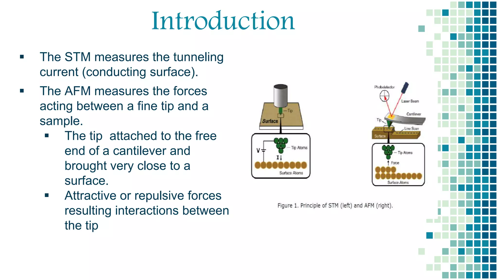
- Atomic force microscopy (AFM) uses a sharp tip to scan over a sample surface and measure forces between the tip and sample. Gerd Binning invented the AFM in 1986.
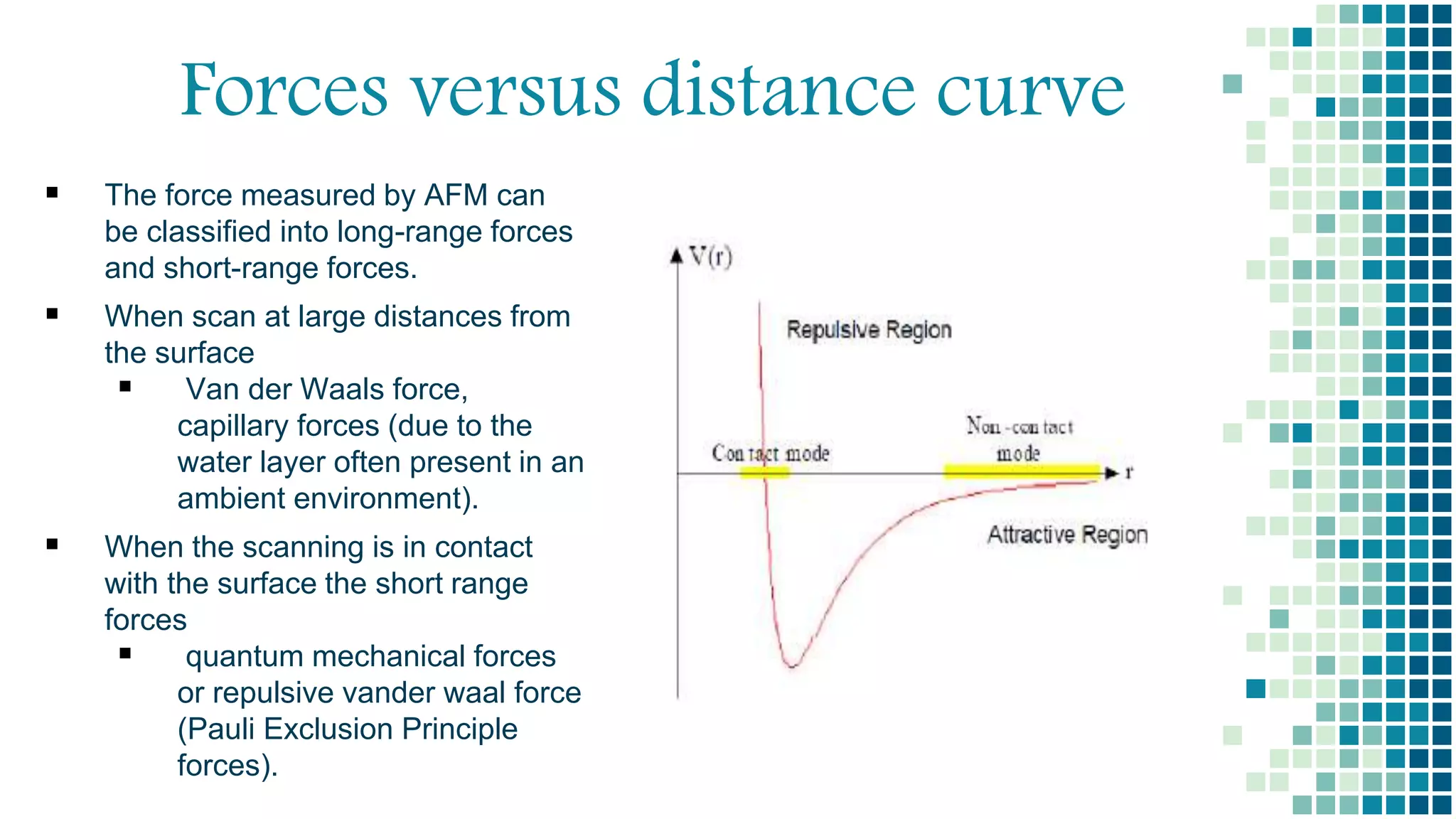
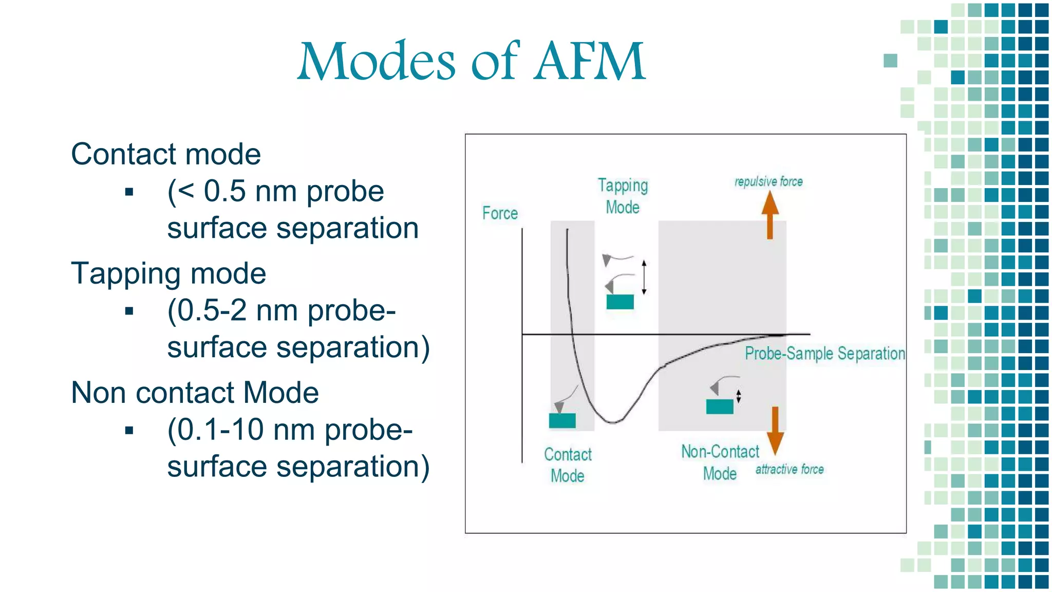
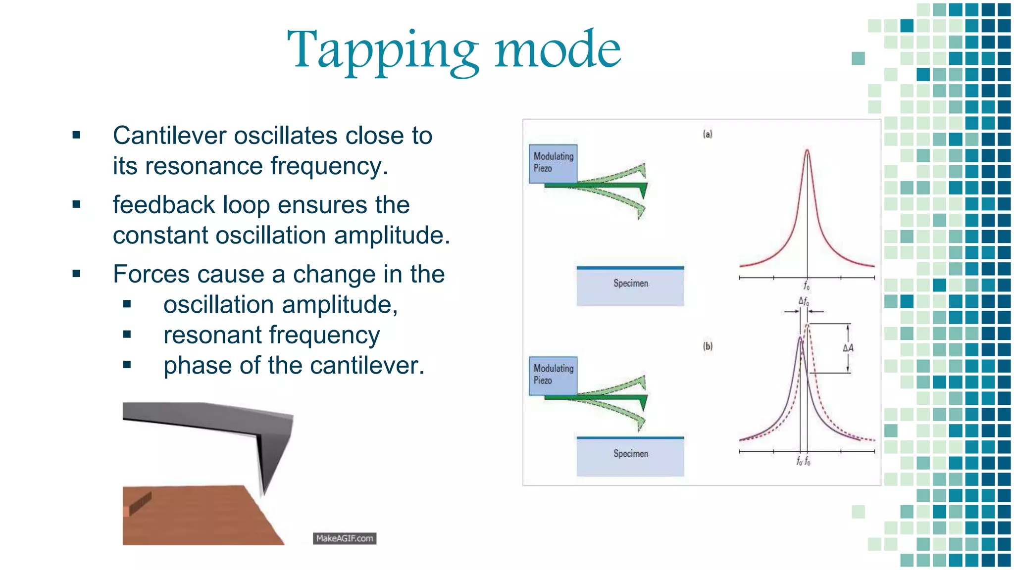
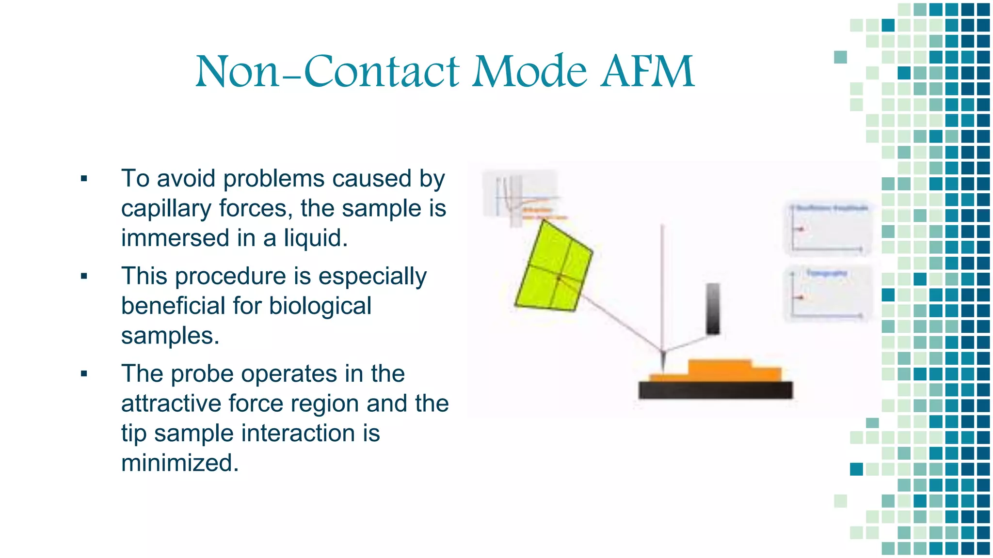
- There are three main imaging modes: contact mode, tapping mode, and non-contact mode. Non-contact mode operates with the tip oscillating above the surface without touching.
- Advantages of non-contact AFM include that it exerts low forces and avoids damaging soft samples or contaminating the tip. Disadvantages include lower resolution and slower scanning speeds. Applications include analyzing surface roughness, thin film growth, and material properties like stiffness.