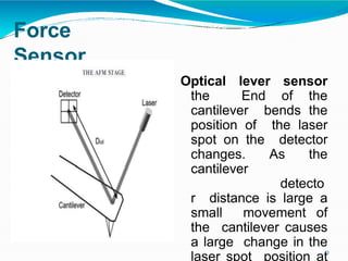
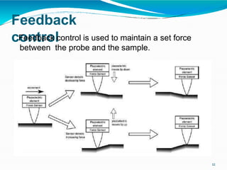
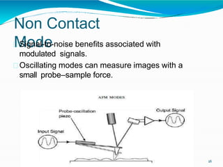
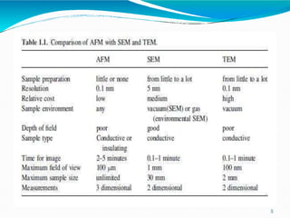
The document summarizes atomic force microscopy (AFM). It describes how AFM works by scanning a probe over a sample surface to build a topography map. The key components of an AFM are a microscope stage, control electronics, and computer. AFM uses a piezoelectric transducer to move the tip over the sample while a force transducer senses the force between them. Different scanning modes are contact, non-contact, and tapping mode. AFM provides high resolution imaging at the single atomic level and can be used to image a variety of biological and material science samples.
2. Atomic Force
Microscopy
AFM works by scanning a probe over the sample
surface, building up a map of the height or
topography of the surface as it goes along.
2
3. Background of
AFM
3
In 1929 Shmalz described Stylus Profiler.
In 1950 Becker suggested oscillating the
probe that approach contact with surface.
In 1971 Young described non contact type Stylus
Profiler.
In 1981 Binning and Rohrer described STM.
AFM Invented in 1986 by Binning.
4. DifferentFrom other
Microscopy
4
No need of focusing, illumination, Depth of field.
It also have height information that make it simple to
quickly measure the height, volume, width of any
feature in the sample.
It physically feels the sample’s surface with a sharp
probe, building up a map of the height of samples
surface.
It provides single atomic level structure so provide
high resolution.
6. The first AFM instrument built by
Binning, Quate and Gerber
The STM with a lever
made by carefully gluing
a tiny diamond onto the
end of a spring made of
a thin strip of gold. This
was the cantilever of
the first AFM.
6
7. AFM
Instrument
7
The main components of an AFM are
1.Microscope stage – Moving AFM tip, Sample
holder, Force Sensor
2.Control electronics - Optical Microscope, Vibration
controller
3.Computer - The control electronics usually takes the
form of a large box interfaced to both the microscope
stage and the computer.
8. Basic concept of AFM
Instrumentation
8
The piezoelectric transducer moves the tip over the
sample surface, the force transducer senses the
force between the tip and the surface, and the
feedback control feeds the signal from the force
transducer back in to the piezoelectric, to maintain a
fixed force between the tip and the sample.
11. Force
Sensor
Optical lever sensor
the End of the
cantilever bends the
position of the laser
spot on the detector
changes. As the
cantilever
detecto
r distance is large a
small movement of
the cantilever causes
a large change in the
laser spot position at
11
14. Challenges of AFM regarding
Design
14
Requirement of sharp probe for high resolution.
The force between probe and sample should be
1nN or less than that.
The feedback controller should have a rapid
control so adjust topographic film can be formed.
A high speed computer that can generate the
images in real time.
Vibration free stage.
16. Modes of Operation in
AFM
16
Mode of Operation
Contact mode strong(repulsive)
-
Force of Interaction
constant force or
constant Height
Non-contact mode weak
(attractive) -
Tapping mode strong (repulsive) -
vibrating
probe
vibrating
probe
17. Contact
Mode
17
High Resolution Images.
Tip of the probe always touching the sample.
Fastest of all the topographic modes.
Because of repulsive forces tip and sample may
damage.
Sensitive to the nature of sample.
Not good for soft samples.
21. Limitation
s
21
AFM can only image a maximum height on the
order of 10-20 micrometers and a maximum
scanning area of about 150×150 micrometers.
The scanning speed of an AFM is also a limitation.
Highly Dependent on AFM probes.
22. Application
s
22
It can image far more biological processes,
such as imaging of proteins.
Any sample like ceramic material, human cells
or individual molecules of DNA, Dispersion of
metallic Nanoparticles can be imaged.