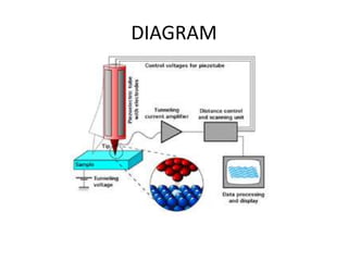
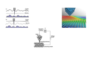
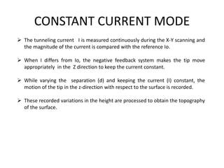
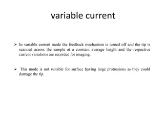
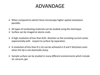
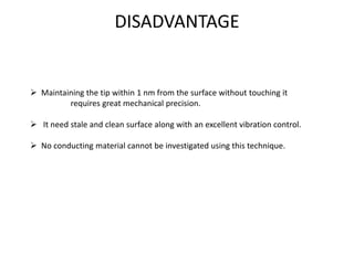
3. SCANNING TUNNELING MICROSCOPE
It is a widely used tool that can image the surface of conducting materials with
atomic resolution.
It has been used to study the deposition and etching of materials to map surface
electronic surface.
4. PRINCIPLE
When a potential difference is applied across the surface to be studied and
a fine metal tip is placed close to the surface, a current tunnels across the
gap.
The magnitude of the current is exponentially dependent on the tip-sample
separation.
The change in the tunneling current, when the tip scans over the surface,
provide the information for surface imaging.
7. TIP AND POSITIONING
The performance of STM depends mainly on the condition of the tip as it determines
the resolution of the instrument.
The tip is made of tungsten, gold or platinum.
It is mechanically or electrochemically sharpened so that it has monoatomic point.
The positioning system consists of coarse positioned and a piezoelectric controlled
x,y and z scanner.
The coarse positioner is used to set the tip sufficiently close to the sample surface.
The xyz scanner is often a cylinder or a tripod made of piezoelectric material. This
scanner makes the tip move laterally across the sample surface.
8. Working
A small voltage is applied between the tip and the sample surface. This
applied voltage is typically a few millivolt to a few volt which depends upon the
material of the sample.
When the tip is brought close enough (5 to 10Å) to the sample, the tunneling
phenomenon occurs which results in a net current in the range of 10pA to 10 nA .
Tunneling is purely a quantum mechanical phenomenon and it is well known
that according to classical mechanics, if there is no contact between the tip and
surface, no current can flow.
The tunneling current varies exponentially with respect to the separation
between the tip and the surface (d) of the sample.
IH= V exp (-2Kd)
Where, K is the wave vector associated with the particles in the tunnel barrier, in this
case, the vacuum between the tip and the sample,
9. MODES
This instrument can be operated in two different modes
1. Constant current mode
2. Variable current mode
10. CONSTANT CURRENT MODE
The tunneling current I is measured continuously during the X-Y scanning and
the magnitude of the current is compared with the reference Io.
When I differs from Io, the negative feedback system makes the tip move
appropriately in the Z direction to keep the current constant.
While varying the separation (d) and keeping the current (I) constant, the
motion of the tip in the z-direction with respect to the surface is recorded.
These recorded variations in the height are processed to obtain the topography
of the surface.
11. variable current
In variable current mode the feedback mechanism is turned off and the tip is
scanned across the sample at a constant average height and the respective
current variations are recorded for imaging.
This mode is not suitable for surface having large protrusions as they could
damage the tip.
12. ADVANDAGE
When compared to atomic force microscope higher spatial resolutions
possible.
All types of conducting materials can be studied using this technique.
Surface can be imaged at atomic scale.
A high resolution of less than 0.01- direction as the tunneling current varies
exponentially with respect to surface tip separation.
A resolution of less than 0.1 nm can be achieved in X and Y directions even
when the tip is not atomically sharp.
Sample surface can be studied in many different environments which include
air, vacuum, gas
13. DISADVANTAGE
Maintaining the tip within 1 nm from the surface without touching it
requires great mechanical precision.
It need stale and clean surface along with an excellent vibration control.
No conducting material cannot be investigated using this technique.