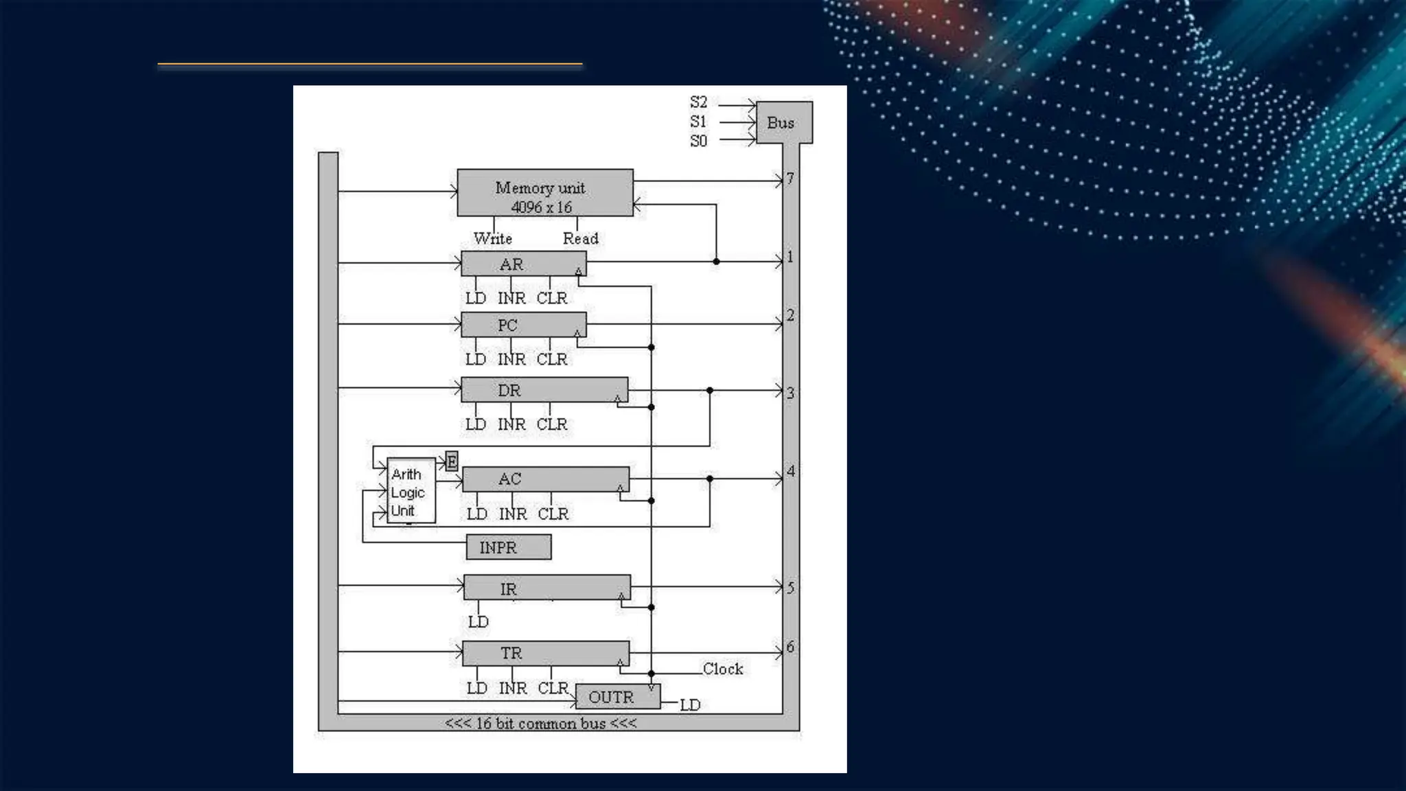
1. COMMON BUS
SYSTEM
Mrs. R. Nancy Beaulah MCA., M.Phil.,
Assistant Professor
Department of Computer Applications
V.V.Vanniaperumal College for Women
Virudhunagar
2. BUS
● A wire or a collection of wires that carry some multi-bit
information is known as bus.
● Main purpose of bus is to transfer information form one
system to another.
● The basic computer has eight registers (AC, PC, DR, AC,
IR, TR, INPR and OUTR), a memory unit and a control
unit.
● Path must be provided to transfer information from one
register to another and between memory and registers.
● A more efficient scheme is to use a common bus.
● Thus common bus provides a path between memory
unit and registers.
3.
4. Five registers have three control inputs: LD (load), INR (increment)
and CLR (clear).
Two registers have only a LD input.
Load (LD):
The lines from the common bus are connected to the inputs of
each register and the data inputs of the memory.
The particular register whose LD input is enabled receives the data
from the bus.
Increment (INR)) and Clear (CLR):
The contents of the particular register are incremented when its
INR signal is enabled and cleared when its CLR signal is enabled.
5. CIRCUIT OPERATION
DESCRIPTION
Memory Unit:
● The memory receives the 16-bit information from the bus when
its write input is enabled and the memory places its 16-bit
information onto the bus when its read input is activated and
S2S1S0 = 111.
Address Register (AR):
● This register specifies the address in memory for next read or
writes operations.
● The address register consists of 12 bits.
● When selection inputs S2S1S0 =001 is applied to the bus, the
address register AR receives or transfers address from or to the
bus when its LD input is enable.
● The address is incremented or clear by the inputs INR or CLR.
6. Program Counter (PC):
● Program counter has 12 bits and it holds the address of the next
instruction to be read from memory after the current execution is
executed.
● When selection inputs S2S1S0 = 010 is applied to the bus, the program
counter (PC) receives or transfers address from or to the bus when its LD
input is enable.
● The address is incremented or clear by the inputs INR or CLR.
Data Register (DR):
● The register DR consists of 16-bits and memory operands (data).
● This register contains the data to be written into memory or receives the
data read from memory.
● When selection inputs S2S1S0 = 011 is applied to the bus, the data register
DR receives or transfers data from or to the bus when its LD input is
enable.
● The data is incremented or clear by the inputs INR or CLR.
7. Accumulator (AC):
● The processor register AC consists of 16 bits.
● The 16-bit inputs to the Adder / logic circuit come from the
outputs of AC.
● They are used to implement register micro operation such as
complement and shift the contents of AC.
● The results of these micro operations are again transferred to
AC.
● So an accumulator is a register in which intermediate
arithmetic and logic results are stored.
● When selection inputs S2S1S0 = 100 is applied to the bus, the
processor register AC receives or transfers its data to the bus by
enabling the LD input of DR, it transfers the contents of DR
through the adder / logic circuit into AC when its LD input is
enable.
● The data of AC is incremented or clear by the inputs INR or
CLR.
8. Instruction Register (IR):
● The instruction register consists of 16-bits.
● The purpose of the instruction register is to hold a copy of the
instruction which the processor is to execute.
● The instruction read from memory is placed in the IR.
● When selection inputs S2S1S0 = 101 is applied to the bus, the
instruction register IR receives or transfers instruction code
from or to the bus when its LD input is enable.
9. Temporary Register (TR):
● Temporary registers have 16 bits. It provides temporary storage of
variables or results.
● When selection inputs S2S1S0 = 111 is applied to the bus, the temporary
register TR receives or transfers temporary data from or to the bus when
its LD input is enable.
● The data is incremented or clear by the inputs INR or CLR.
Input Register (INPR):
● The Input Register INPR consists of 8-bits and hold alphanumeric input
information.
● The serial information from the input device is shifted into input of 8-bit
register INPR.
● When LD input of AC is enabled, the 8-bit information of INPR is
transferred to the AC via Adder/logic circuit.
10. ● Output Register (OUTR):
● The output OUTR receives information from AC and
transfers it to the output device.