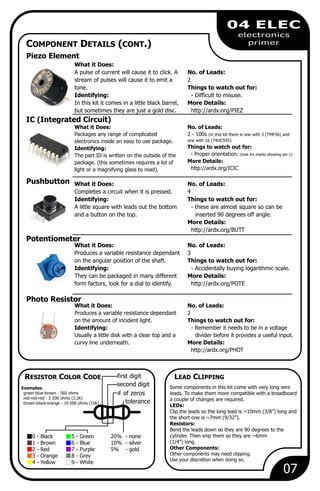
Here are the key things to know about some common electronic components:
DC Motor:
- What it Does: Spins when a current is passed through its leads. It converts electrical energy to mechanical motion/rotation.
- No. of Leads: Typically has 2 leads - one positive and one negative. Current must flow through the motor in one direction for it to spin.
LED (Light Emitting Diode):
- What it Does: Emits light when current passes through it in the correct direction. Common colors are red, green, blue, yellow, white.
- No. of Leads: Has 2 leads, one longer than the other. The longer lead is positive and must be connected to


![Wire
10
CIRC-02
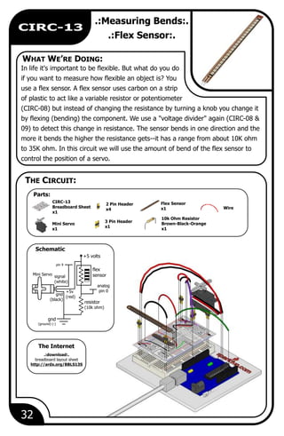
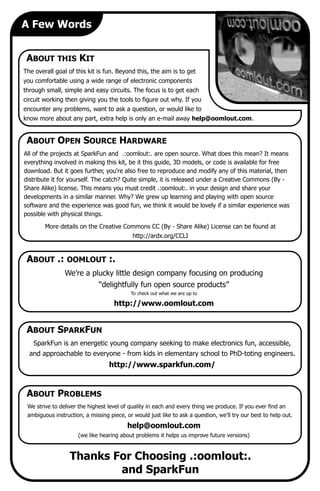
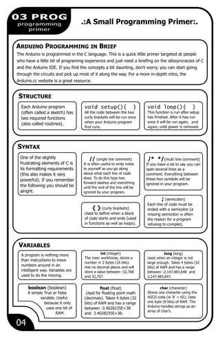
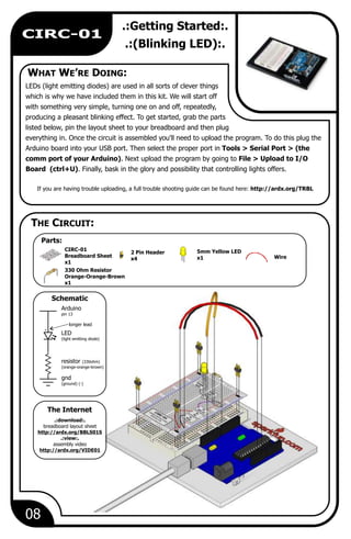
.:8 LED Fun:.
.:Multiple LEDs:.
We have caused one LED to blink, now it's time to up the
stakes. Lets connect eight. We'll also have an opportunity to
stretch the Arduino a bit by creating various lighting
sequences. This circuit is also a nice setup to experiment with
writing your own programs and getting a feel for how the Arduino works.
Along with controlling the LEDs we start looking into a few simple programming methods to
keep your programs small.
for() loops - used when you want to run a piece of code several times.
arrays[] - used to make managing variables easier (it's a group of variables).
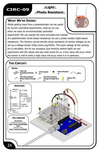
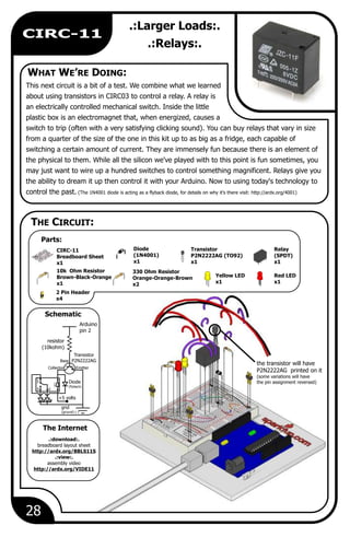
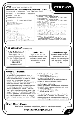
5mm Yellow LED
x8
330 Ohm Resistor
Orange-Orange-Brown
x8
2 Pin Header
x4
CIRC-02
Breadboard Sheet
x1
.:download:.
breadboard layout sheet
http://ardx.org/BBLS02S
.:view:.
assembly video
http://ardx.org/VIDE02
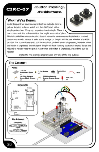
LED
resistor
330ohm
gnd
pin 3pin 2 pin 4 pin 5
LED
resistor
330ohm
gnd
pin 7pin 6 pin 8 pin 9
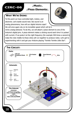
WHAT WE’RE DOING:
The Internet
THE CIRCUIT:
Schematic
Parts:](https://image.slidesharecdn.com/ardx-eg-spar-web-rev10-170317120215/85/Ardx-eg-spar-web-rev10-12-320.jpg)
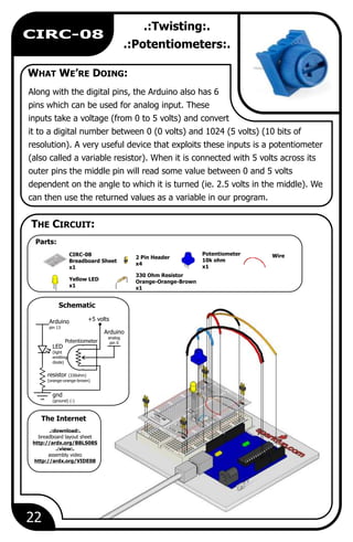
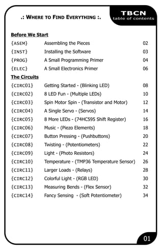
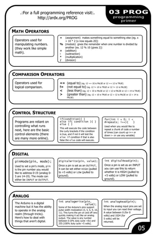
![NOT WORKING? (3 things to try)
MAKING IT BETTER
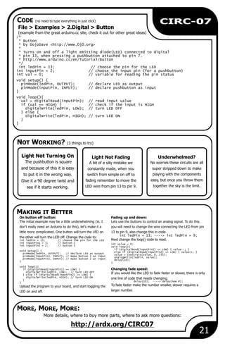
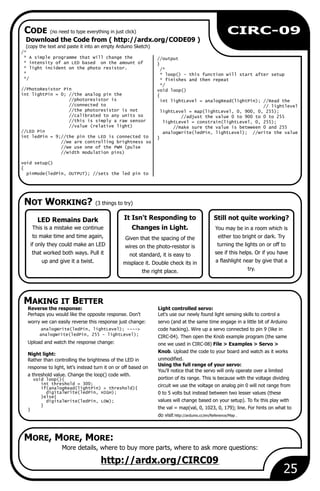
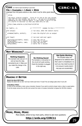
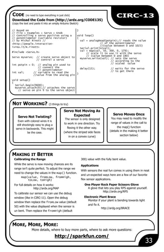
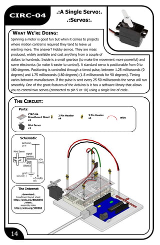
CODE (no need to type everything in just click)
MORE, MORE, MORE:
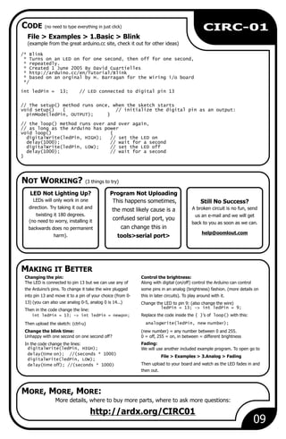
Operating out of sequence
With eight wires it's easy to cross
a couple. Double check that the
first LED is plugged into pin 2 and
each pin there after.
11
CIRC-02
Download the Code from ( http://ardx.org/CODE02 )
(and then copy the text and paste it into an empty Arduino Sketch)
More details, where to buy more parts, where to ask more questions:
http://ardx.org/CIRC02
Some LEDs Fail to Light
It is easy to insert an LED
backwards. Check the LEDs
that aren't working and ensure
they the right way around.
Switching to loops: Extra animations:
Tired of this animation? Then try the other twoIn the loop() function there are 4 lines. The last
sample animations. Uncomment their lines and uploadthree all start with a '//'. This means the line is
the program to your board and enjoy the new lighttreated as a comment (not run). To switch the
animations. (delete the slashes in front of row 3 and then 4)program to use loops change the void loop()
code to:
Testing out your own animations://oneAfterAnotherNoLoop();
oneAfterAnotherLoop(); Jump into the included code and start changing
//oneOnAtATime();
things. The main point is to turn an LED on use//inAndOut();
digitalWrite(pinNumber, HIGH); then to turn
Upload the program, and notice that nothing has
it off use digitalWrite(pinNumber, LOW); .changed. You can take a look at the two
functions, each does the same thing, but use Type away, regardless of what you change you won't
different approaches (hint: the second one uses break anything.
a for loop).
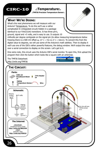
Starting Afresh
Its easy to accidentally
misplace a wire without
noticing. Pulling everything out
and starting with a fresh slate
is often easier than trying to
track down the problem.
//LED Pin Variables * will then turn them off
int ledPins[] = {2,3,4,5,6,7,8,9};
//An array to hold the void oneAfterAnotherNoLoop(){
//pin each LED is connected to int delayTime = 100;
//i.e. LED #0 is connected to pin 2 //the time (in milliseconds) to pause
//between LEDs
void setup() digitalWrite(ledPins[0], HIGH); //Turns on LED #0
{ //(connected to pin 2)
for(int i = 0; i < 8; i++){ delay(delayTime); //waits delayTime milliseconds
//this is a loop and will repeat eight times ...
pinMode(ledPins[i],OUTPUT); ...
//we use this to set LED pins to output digitalWrite(ledPins[7], HIGH); //Turns on LED #7
} //(connected to pin 9)
} delay(delayTime); //waits delayTime milliseconds
//Turns Each LED Off
void loop() // run over and over again digitalWrite(ledPins[7], LOW); //Turns off LED #7
{ delay(delayTime); //waits delayTime milliseconds
oneAfterAnotherNoLoop(); ...
//this will turn on each LED one by
//one then turn each oneoff -----more code in the downloadable version------
//oneAfterAnotherLoop();
//this does the same as onAfterAnotherNoLoop
//but with much less typing
//oneOnAtATime();
//inAndOut();
}
/*
* oneAfterAnotherNoLoop() - Will light one then
* delay for delayTime then light the next LED it](https://image.slidesharecdn.com/ardx-eg-spar-web-rev10-170317120215/85/Ardx-eg-spar-web-rev10-13-320.jpg)

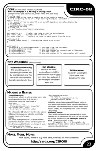
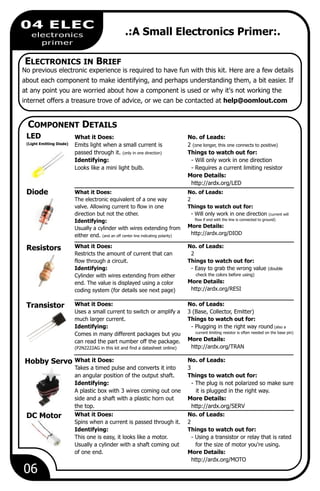
![NOT WORKING? (3 things to try)
MAKING IT BETTER
MORE, MORE, MORE:
19
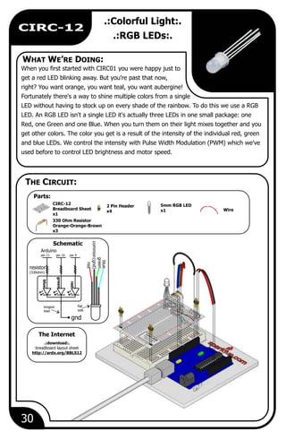
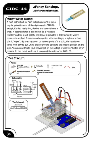
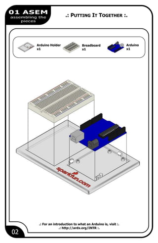
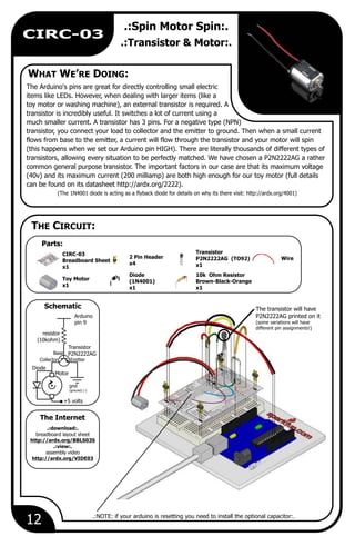
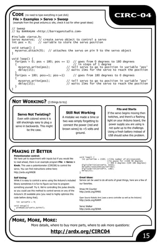
CIRC-06
Can't Think While the
Melody is Playing?
Just pull up the piezo element
whilst you think, upload your
program then plug it back in.
More details, where to buy more parts, where to ask more questions:
http://ardx.org/CIRC06
No Sound
Given the size and shape of
the piezo element it is easy to
miss the right holes on the
breadboard. Try double
checking its placement.
char names[] = { 'c', 'd', 'e', 'f', 'g', 'a', 'b',Playing with the speed:
'C' };The timing for each note is calculated based on int tones[] = { 1915, 1700, 1519, 1432, 1275, 1136,
variables, as such we can tweak the sound of each note 1014, 956 };
or the timing. To change the speed of the melody you Composing your own melodies:
need to change only one line. The program is pre-set to play 'Twinkle Twinkle Little Star'
int tempo = 300; ---> int tempo = (new #) however the way it is programmed makes changing the song
Change it to a larger number to slow the melody down,
easy. Each song is defined in one int and two arrays, the int
or a smaller number to speed it up.
length defines the number of notes, the first arrayTuning the notes:
notes[] defines each note, and the second beats[]If you are worried about the notes being a little out of
defines how long each note is played. Some Examples:tune this can be fixed as well. The notes have been
Twinkle Twinkle Little Starcalculated based on a formula in the comment block at int length = 15;
char notes[] = {"ccggaagffeeddc "};the top of the program. But to tune individual notes just
int beats[] = { 1, 1, 1, 1, 1, 1, 2, 1, 1, 1, 1,
adjust their values in the tones[] array up or down 1, 1, 2, 4 };
Happy Birthday (first line)until they sound right. (each note is matched by its
int length = 13;
name in the names[] (array ie. c = 1915 ) char notes[] = {"ccdcfeccdcgf "};
int beats[] = {1,1,1,1,1,2,1,1,1,1,1,2,4};
Tired of Twinkle Twinkle
Little Star?
The code is written so you can
easily add your own songs,
check out the code below to
get started.
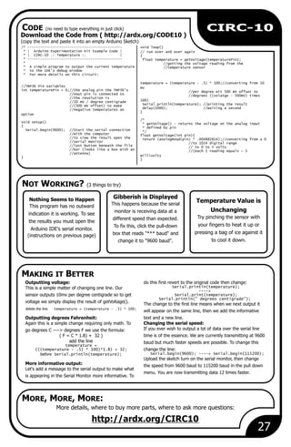
/* Melody
* (cleft) 2005 D. Cuartielles for K3
* digitalWrite(speakerPin,
* This example uses a piezo speaker to play melodies. It sends LOW);
* a square wave of the appropriate frequency to the piezo, delayMicroseconds(tone);
* generating the corresponding tone. }
* }
* The calculation of the tones is made following the
* mathematical operation: void playNote(char note, int duration) {
* char names[] = { 'c', 'd', 'e', 'f', 'g', 'a', 'b', 'C' };
* timeHigh = period / 2 = 1 / (2 * toneFrequency) int tones[] = { 1915, 1700, 1519, 1432, 1275, 1136, 1014, 956
*
};* where the different tones are described as in the table:
// play the tone corresponding to the note name*
for (int i = 0; i < 8; i++) {* note frequency period timeHigh
if (names[i] == note) {* c 261 Hz 3830 1915
playTone(tones[i], duration);* d 294 Hz 3400 1700
}* e 329 Hz 3038 1519
}* f 349 Hz 2864 1432
}* g 392 Hz 2550 1275
* a 440 Hz 2272 1136
void setup() {* b 493 Hz 2028 1014
pinMode(speakerPin, OUTPUT);* C 523 Hz 1912 956
}*
* http://www.arduino.cc/en/Tutorial/Melody
void loop() {*/
for (int i = 0; i < length; i++) {
if (notes[i] == ' ') {int speakerPin = 9;
delay(beats[i] * tempo); // restint length = 15; // the number of notes
} else {char notes[] = "ccggaagffeeddc "; // a space represents a rest
playNote(notes[i], beats[i] * tempo);int beats[] = { 1, 1, 1, 1, 1, 1, 2, 1, 1, 1, 1, 1, 1, 2, 4 };
}int tempo = 300;
// pause between notes
delay(tempo / 2); }void playTone(int tone, int duration) {
}for (long i = 0; i < duration * 1000L; i += tone * 2) {
digitalWrite(speakerPin, HIGH);
delayMicroseconds(tone);
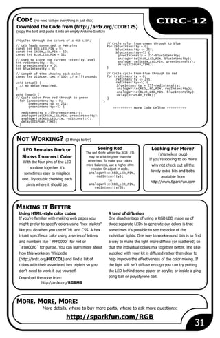
Download the Code from ( http://ardx.org/CODE06 )
(copy the text and paste it into an empty Arduino Sketch)
CODE (no need to type everything in just click)](https://image.slidesharecdn.com/ardx-eg-spar-web-rev10-170317120215/85/Ardx-eg-spar-web-rev10-21-320.jpg)